Numatics G3 Series EtherNet/IP User manual

G3 Series
EtherNet/IPTM DLR
Technical Manual

G3 Series EtherNet/IPTM DLR Technical Manual
1-2
TDG3EDM1-6EN 3/18
Subject to change without notice
www.asco.com/g3
Conditions for use of this product
(1) Numatics G3 Manifold ("the PRODUCT") shall be used in conditions;
i) Where any problem, fault or failure occurring in the PRODUCT, if any, shall not lead to any major or serious accident.
ii) Where the backup and fail-safe function are systematically or automatically provided outside of the PRODUCT for the case of
any problem, fault or failure occurring in the PRODUCT.
(2) The PRODUCT has been designed and manufactured for use in general industries.
Numatics Incorporated shall have no responsibility or liability including but not limited to any and all responsibility or liability
based on contract, warranty, tort, product liability for any injury or death to persons, loss or damage to property caused by the
product that are operated or used in application not intended or excluded by instructions, precautions or warnings contained in
Numatics Inc. Technical, User, Instruction, Safety manuals or bulletins.
Safety precautions
Before using this product, please read this manual and the relevant manuals carefully and pay attention to safety and product
application. The following symbols are used in the manual to identify important safety, installation and application information.
Caution symbol indicates a possible hazard which may cause injury or equipment damage.
Note symbol indicates important information regarding equipment installation and setup
NOTE!
CAUTION

G3 Series EtherNet/IPTM DLR Technical Manual
1-3
TDG3EDM1-6EN 3/18
Subject to change without notice
www.asco.com/g3
Electrical installation and operational guidelines
•To be connected to Class 2 power source only
•All Numatics Inc. communication nodes should be grounded during the installation process. These grounding
guidelines can be found in National Electrical code IEC 60204-1 or EN 60204-1.
•All Numatics G3 Electronics Products to be installed or wired in accordance with ASCO Numatics published instructions
and applicable electrical codes.
•MULTIPLE CLASS 2 POWER SOURCES: When interconnects, class 2 sources shall be Listed and rated suitable for
parallel interconnection
•Sources shall be Listed and rated suitable for parallel interconnection
•CLASS 2 WIRING: All field wiring shall be suitable for Class 1, Electric Light and Power, or Class 2, 3 wirings are routed
separately and secured to maintain separation between 1) Class 2 wiring and all other class wiring, and 2) Limited
energy circuit conductors from unlimited energy circuit conductors
•Class 2 Device Wiring Only –Do Not Reclassify and Install as Class 1, 3 or Power and Lighting Wiring
•When using molded connector power cables, Do Not rely on wire colors for Pin-Out. Always use pin number
references.
•Wire connections shall be rated suitable for the wire size (lead and building wiring) employed
•MULTIPLE CLASS 2 POWER SOURCES: When interconnects, class 2 sources shall be Listed and rated suitable for
parallel interconnection
•Sources shall be Listed and rated suitable for parallel interconnection
CAUTION

G3 Series EtherNet/IPTM DLR Technical Manual
1-4
TDG3EDM1-6EN 3/18
Subject to change without notice
www.asco.com/g3
Table of Contents
1. About EtherNet/IPTM ................................................................................................................................................. 6
1.1 Overview................................................................................................................................................................ 6
1.2 G3 EtherNet/IPTM Features.................................................................................................................................. 6
1.3 G3 EtherNet/IPTM Performance Data .................................................................................................................. 6
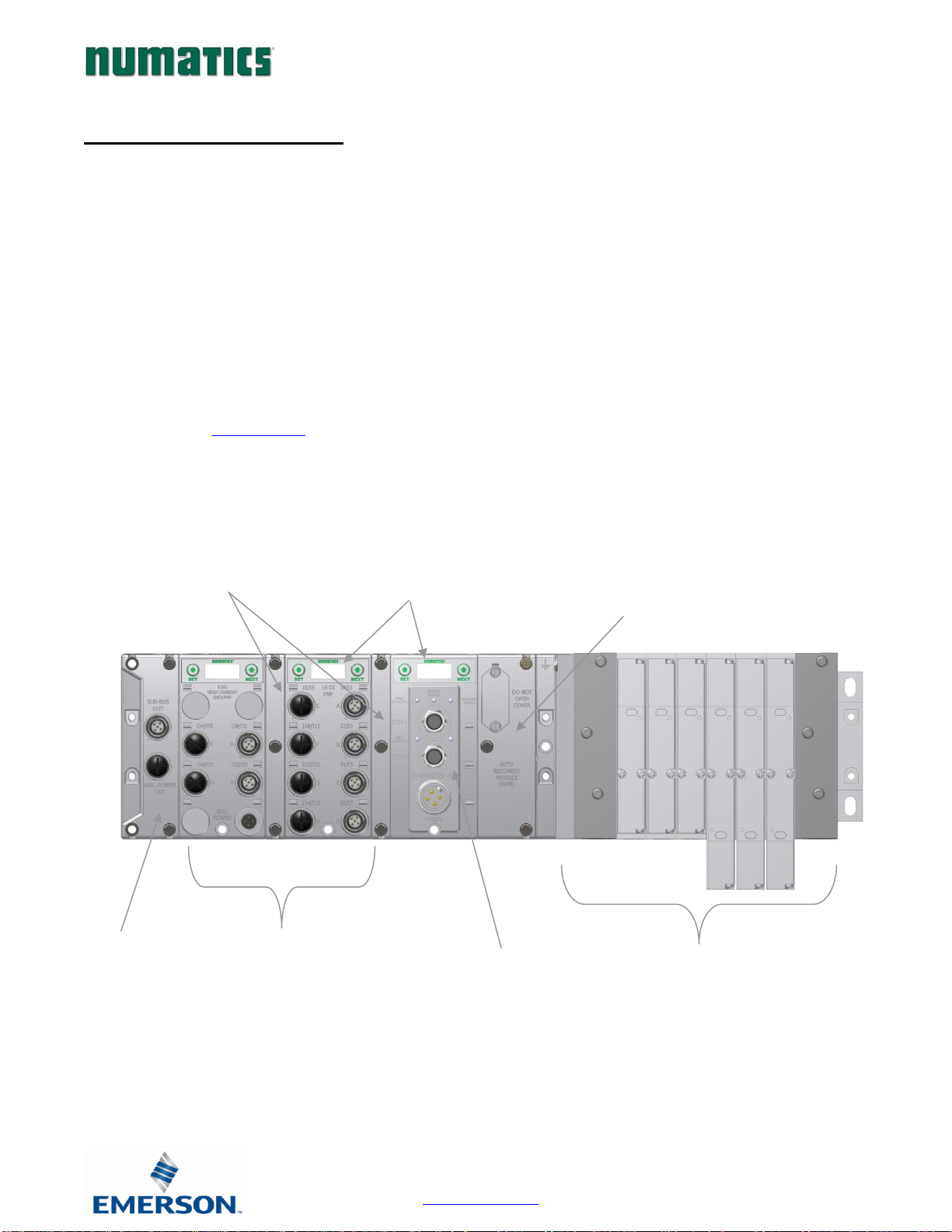
2. G3 Introduction ....................................................................................................................................................... 7
2.1 G3 Electronics Modularity..................................................................................................................................... 8
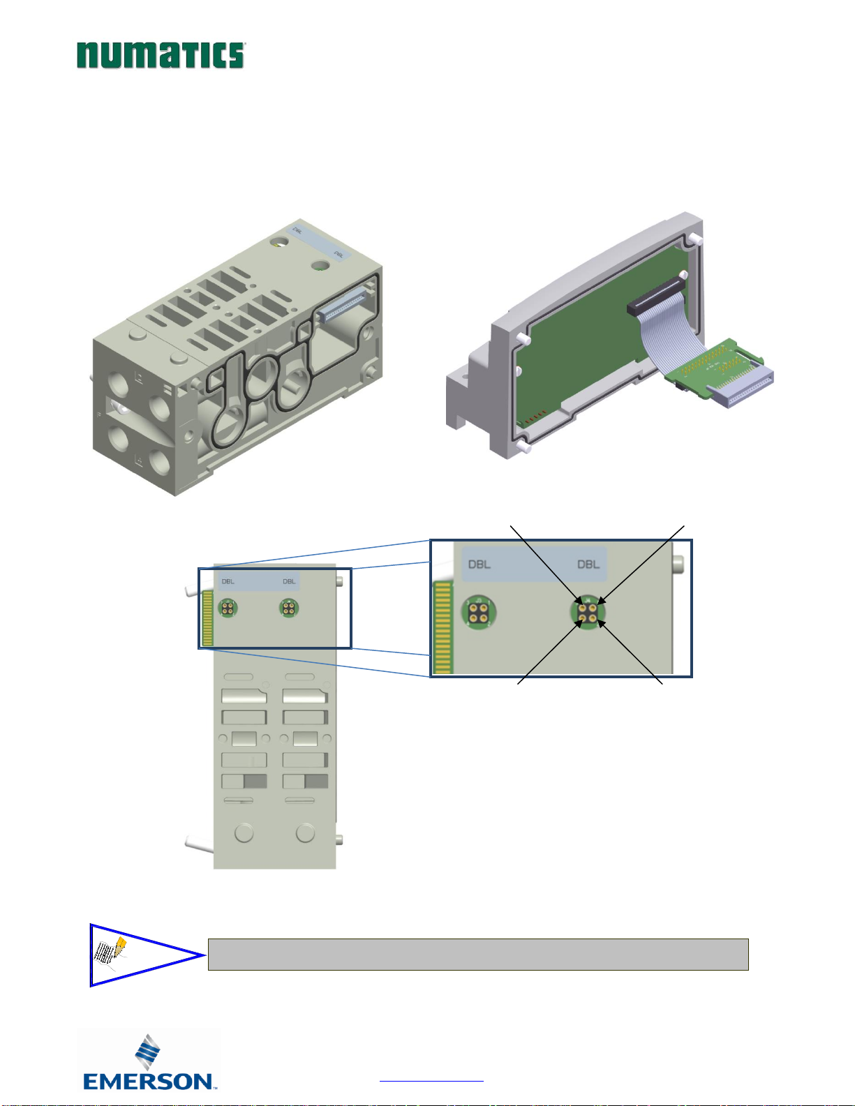
2.2 500 Series Pneumatic Valve Manifold.................................................................................................................... 9
2.3 500 Series Manifold Stations .................................................................................................................................10
2.4 500 Series Standard Z-Board™ Connectors .........................................................................................................11
2.5 2000 Series Pneumatic Valve Manifold.................................................................................................................12
2.6 2000 Series Z-Board™ Connectors.......................................................................................................................13
2.7 2000 Series Z-Board™ and Ribbon Cable Example............................................................................................14
2.8 2000 Series Z-Board™ with Valve Side Sub-D Example ......................................................................................15
3. Zoned Power......................................................................................................................................................... 16
3.1 503 Series Zoned Power application .....................................................................................................................16
3.2 503 Series Zoned Power example .........................................................................................................................17
4. Communication Module .......................................................................................................................................... 18
4.1 EtherNet/IP DLR Communication Module (Node) ...........................................................................................18
4.2 Communication Module Description...................................................................................................................19
4.3 Connector Pin-Outs............................................................................................................................................. 20
4.4 Electrical Connections .........................................................................................................................................21
4.5 Ground Wiring..................................................................................................................................................... 23
4.6 Power Consumption ............................................................................................................................................ 24
4.7 Diagnostics.......................................................................................................................................................... 26
5. G3 Graphic Display ................................................................................................................................................ 28
5.1 Main Menu Structure .......................................................................................................................................... 29
5.2 IP Address ........................................................................................................................................................... 30
5.3 Subnet Mask .........................................................................................................................................................31
5.4 Gateway IP .......................................................................................................................................................... 32
5.5 DHCP-BOOTP ................................................................................................................................................... 33
5.6 Config. Mode....................................................................................................................................................... 34
5.7 Web-Server........................................................................................................................................................... 35
5.8 MAC Address....................................................................................................................................................... 36
5.9 Advanced Settings –Comm. Fault ...................................................................................................................... 37
5.10 Advanced Settings - Brightness........................................................................................................................... 38
5.11 Advanced Settings –Flip Display........................................................................................................................ 39
5.12 Advanced Settings –Comm. Format................................................................................................................... 40
5.13 Advanced Settings –Parameters Lock .................................................................................................................41
5.14 Advanced Settings –Configuration Lock ............................................................................................................ 42
5.15 Advanced Settings –Quick Connect ................................................................................................................... 43
5.16 Advanced Settings –Compatibility Mode ........................................................................................................... 44
5.17 Factory Defaults .................................................................................................................................................. 45
5.18 Diagnostics.......................................................................................................................................................... 46
5.19 Diagnostics - Self Test Mode .............................................................................................................................. 47
5.20 Error Messages.................................................................................................................................................... 48
6. ARM –Auto Recovery Module (Optional) .................................................................................................................. 49
6.1 ARM process flowchart ....................................................................................................................................... 50
7. Distribution........................................................................................................................................................... 51
7.1 Sub-Bus Distribution Modules............................................................................................................................ 52
7.2 Sub-Bus Cables.................................................................................................................................................... 58
8. Digital I/O Module.................................................................................................................................................. 60
8.1 Digital I/O Module Usage .................................................................................................................................. 60
8.2 I/O Module Technical Data ................................................................................................................................61
8.3 I/O Module Descriptions and Menus................................................................................................................. 62
8.4 Digital Input Modules ......................................................................................................................................... 63
8.5 Digital Output Modules .......................................................................................................................................71

G3 Series EtherNet/IPTM DLR Technical Manual
1-5
TDG3EDM1-6EN 3/18
Subject to change without notice
www.asco.com/g3
8.6 Digital Input/Output Modules ........................................................................................................................... 75
9. Valve Interface Modules ......................................................................................................................................... 76
9.1 2000 Series & 500 Series Valve Driver .................................................................................................................. 76
9.2 Sub-bus Valve Module......................................................................................................................................... 78
9.3 Sub-bus Valve Module without Distribution and I/O ........................................................................................ 80
7.4 Valve Side Digital Output Modules.................................................................................................................... 82
9.5 500 Series Extended Coil Capability.................................................................................................................... 83
9.6 Extended Coil Configuration .............................................................................................................................. 83
9.7 Extended Coil Valve driver IO Mapping............................................................................................................. 86
9.8 501 Series, up to 64 solenoid coils ........................................................................................................................ 87
9.9 501 Series, up to 128 solenoid coils ...................................................................................................................... 88
9.10 502 and 503 Series, up to 80 coils ......................................................................................................................... 89
10. Analog I/O Modules.............................................................................................................................................. 90
10.1 Analog I/O Module Rules................................................................................................................................... 90
10.2 Analog Graphic Display ...................................................................................................................................... 97
10.3 Analog Module / Self Test Mode .......................................................................................................................100
10.4 Analog Module / Factory Defaults..................................................................................................................... 101
11. Specialty Modules .............................................................................................................................................. 102
11.1 RTD Module .....................................................................................................................................................102
11.2 Sub-Bus Hub Module......................................................................................................................................... 113
12. I/O Module Wiring Diagrams................................................................................................................................ 121
12.1 NPN/PNP Definitions ...................................................................................................................................... 121
13. EtherNet/IPTM G3 Web Server .............................................................................................................................. 123
13.1 Integrated Web Page Configuration...................................................................................................................123
13.2 Connecting to a G3 Series EtherNet/IPTM Node ..............................................................................................123
13.3 EtherNet/IPTM Web Server functionality...........................................................................................................127
13.4 IP Address Configuration...................................................................................................................................136
13.5 User Configurable Device Parameters ...............................................................................................................137
13.6 Communication Fault/Idle Mode Parameter ....................................................................................................138
14. EtherNet/IPTM Commissioning .............................................................................................................................. 139
14.1 G3 configuration for RSLogix 5000 (Rockwell Generic Ethernet Module) ........................................................139
14.2 G3 configuration for RSLogix 5000 (Numatics G3 EDS File)............................................................................ 141
15. EtherNet/IPTM Mapping........................................................................................................................................ 144
15.1 I/O Sizes ............................................................................................................................................................144
15.2 Manifold and I/O Data Sizing Worksheet .........................................................................................................145
15.3 Bit Mapping Rules .............................................................................................................................................146
15.4 Example No. 1 ....................................................................................................................................................147
16.5 Example No. 2....................................................................................................................................................149
15.6 Example No. 3.................................................................................................................................................... 151
15.7 Example No. 4....................................................................................................................................................153
15.8 Example No. 5....................................................................................................................................................155
15.9 Diagnostic Word.................................................................................................................................................157
16. Appendix .......................................................................................................................................................... 159
16.1 System Specifications .........................................................................................................................................159
16.2 Factory Default Settings .....................................................................................................................................160
16.3 Troubleshooting ................................................................................................................................................. 161
16.4 Glossary of Terms...............................................................................................................................................162
16.5 Technical Support ..............................................................................................................................................164

G3 Series EtherNet/IPTM DLR Technical Manual
1-6
TDG3EDM1-6EN 3/18
Subject to change without notice
www.asco.com/g3
1. About EtherNet/IPTM
1.1 Overview
EtherNet/IPTM is a communication protocol that uses the same network technology that can be found in commercial and
domestic operations worldwide, but has added benefits/features toward manufacturing applications. It is a CIP (common
industrial protocol) Network that follows the Open Systems Interconnection (OSI) model.
The ODVA (Open Device Net Vendor Association) is an independent organization that governs the EtherNet/IPTM
specification and oversees conformance testing for products.
EtherNet/IPTM uses industrial M12 IP67-rated connectors. The protocol can transfer data at two interface speeds of 10
Mbps and 100 Mbps. Maximum network cabling distance is limited to 100m segments at 20º C.
More information about EtherNet/IPTM and ODVA can be obtained from the ODVA web site www.odva.org
Device level ring or DLR network technology for industrial applications takes advantage of embedded switch
functionality within the associated EtherNet/IPTM communication modules. DLR technology adds device-level network
resilience to optimize machine operation. When a DLR network detects a break in the ring, it provides alternate routing
of the data to help recover the network at extremely fast rates. Enhanced diagnostics built into DLR-enabled products
identify the point of failure, helping to speed maintenance and reduce mean time to repair. The DLR module is works
equally well in both Linear and Ring configurations.
1.2 G3 EtherNet/IPTM Features
1.3 G3 EtherNet/IPTM Performance Data
Features
Description
EtherNet/IPTM Spec.
Supported
Designed to EtherNet/IPTM and DLR Specification
Bus Topology
Star and Multi-Star and Ring
Baud Rates Supported
10/100 Mbps and Autobaud
CE
CE Compliant
Duplicate Address Detection
If a duplicate address is detected on power up, duplicates will not
progress to run mode
Address Setting
Via DHCP/BOOTP, Webserver Configuration or Graphical Display
Interface
Duplex
Half and Full supported
Conformance Tested
Tested by ODVA for conformance
Protocols supported
ACD, ARP, DHCP, HTTP, TCP/IP, UDP
Features
Description
CIP connections consumed
1
CIP connections available
16
Packets per second (PPS)
10,000
RPI
≥ 5ms
Connection Type
Multicast, Unicast

G3 Series EtherNet/IPTM DLR Technical Manual
2-7
TDG3EDM1-6EN 3/18
Subject to change without notice
www.asco.com/g3
2. G3 Introduction
The G3 Series is an electronic product platform that features an integrated graphic display for simple commissioning and
displaying of diagnostic information. The G3 offers innovative distribution capability which allows the same I/O components
that make up a centralized manifold configuration to be used as the distribution components as well, decreasing the need for
duplicate components on centralized and distributed applications. The G3 platform interfaces to a variety of valve series and
fieldbus interface protocols and can address a total of 1200 I/O points (150 bytes). With proper assembly and termination, the
G3 modules will have an IP65 / IP67 rating.
The manifold can be viewed as having two sections to it, the Valve Side and the Discrete I/O Side. The Valve Side
supports a maximum of 128 solenoid coils and the Discrete I/O Side supports a maximum of 16 modules capable of
addressing up to 1200 outputs, 1200 inputs or various combinations.
Various discrete modules with integrated graphic display are available. They include digital I/O, analog I/O, and
specialty modules which cover various application needs. Pin-outs for all connectors are labeled on the side of the
respective modules and are also detailed in the module section of this document.
This manual details specific information for configuring and commissioning the Numatics G3 Series product line. For
more information relating to pneumatic valves and valve manifold assemblies, please refer to the Numatics “In Control
“catalog at www.asco.com.
Discrete I/O Side
Accepts up to 16 modules in
centralized or distributed configuration
Communication Module (Node)
Available with various
Industrial protocols
Sub-Bus OUT
Used to distribute
additional I/O and
manifolds
Valve Side
Drives up to 128 coils
Clips
Allows easy field changes of electronic
modules.
Graphic Display
Allows Easy Configuration
& Diagnostic reporting
ARM
(Auto Recovery Module)
Automatically stores & reprograms
configuration information

G3 Series EtherNet/IPTM DLR Technical Manual
2-8
TDG3EDM1-6EN 3/18
Subject to change without notice
www.asco.com/g3
2.1 G3 Electronics Modularity
Discrete I/O
The G3 Series product line is a completely modular and scalable system. As shown below, the G3 electronic modules plug
together, via mechanical clips, allowing for easy assembly and field changes.

G3 Series EtherNet/IPTM DLR Technical Manual
2-9
TDG3EDM1-6EN 3/18
Subject to change without notice
www.asco.com/g3
2.2 500 Series Pneumatic Valve Manifold
The pneumatic valve manifold with internal circuit board technology is also modular. The valve solenoid coil connections are
automatically made using Z-Board™technology (plug together PC boards), which allow internal connection from solenoid coils
to output drivers without the use of wires). This allows easy assembly and field changes.

G3 Series EtherNet/IPTM DLR Technical Manual
2-10
TDG3EDM1-6EN 3/18
Subject to change without notice
www.asco.com/g3
2.3 500 Series Manifold Stations
Z-Board™plug together technology connects all valve solenoids to the valve coil output driver board, located in the valve
adapter. There is a maximum of 128 coil outputs available on the complete manifold assemblies. The 128 available outputs are
accessed on the 501 series valves utilizing 4 station manifolds and on the 502 and 503 series utilizing 2 station manifolds.
Solenoid Coil Connections using Z-Board™ Technology for 50x valve series
A single solenoid valve’s coil is always on the “14” end.
14 Solenoid,
Pin No. 1
Common,
Pin No. 4
12 Solenoid,
Pin No. 2
Not Used,
Pin No. 3
NOTE!

G3 Series EtherNet/IPTM DLR Technical Manual
2-11
TDG3EDM1-6EN 3/18
Subject to change without notice
www.asco.com/g3
2.4 500 Series Standard Z-Board™ Connectors
The 501, 502 and 503 valve series utilize 2 different Z-Board™designs to achieve the single and double solenoid
output functions.
501 Series
502 Series
503 Series

G3 Series EtherNet/IPTM DLR Technical Manual
2-12
TDG3EDM1-6EN 3/18
Subject to change without notice
www.asco.com/g3
2.5 2000 Series Pneumatic Valve Manifold
The pneumatic valve manifold with internal circuit board technology is also modular. The valve solenoid coil
connections are automatically made using Z-Board™technology (plug together PC boards), which allow internal
connection from solenoid coils to output drivers without the use of wires). This allows easy assembly and field
changes.

G3 Series EtherNet/IPTM DLR Technical Manual
2-13
TDG3EDM1-6EN 3/18
Subject to change without notice
www.asco.com/g3
2.6 2000 Series Z-Board™ Connectors
The 2005/2012/2035 valve series utilize 2 different Z-Board™designs to achieve the single and double solenoid
output functions. This yields the possible 32 single, 16 double, or various combinations of valve coil output
capabilities.
Single Z-Board™
Double Z-Board™
Ribbon Connection
Single Z-Board™
Ribbon Connection
Double Z-Board™
single
double
The 17th solenoid (output group No. 2’s first bit) must be accessed via either
the valve side Sub-D output module or a ribbon connector type Z-board.
NOTE!

G3 Series EtherNet/IPTM DLR Technical Manual
2-14
TDG3EDM1-6EN 3/18
Subject to change without notice
www.asco.com/g3
2.7 2000 Series Z-Board™ and Ribbon Cable Example
If fourteen (14) single solenoid and one (1) double solenoid valves are connected directly to the communication
node through the associated Z-Boards™. one (1) single solenoid and four (4) double solenoid valves are connected
to the communication node via the ribbon cable, the following would be the valve side bit map:
Output Word
0
1
Output Byte
0
1
2
3
Output Bit No.
00
01
02
03
04
05
06
07
08
09
10
11
12
13
14
15
16
17
18
19
20
21
22
23
24
25
26
27
28
29
30
31
Solenoid Coil
Output No.
1
2
3
4
5
6
7
8
9
10
11
12
13
14
15
16
17
18
19
20
21
22
23
24
25
n/a

G3 Series EtherNet/IPTM DLR Technical Manual
2-15
TDG3EDM1-6EN 3/18
Subject to change without notice
www.asco.com/g3
2.8 2000 Series Z-Board™ with Valve Side Sub-D Example
If sixteen (16) single solenoid valves are connected directly to the communication node via Z-Boards™and a valve
side Sub-D connector is connected to the communication node via the output Group No. 2 connector then the
following would be the valve side bit map:
Output Word
0
1
Output Byte
0
1
2
3
Output Bit No.
00
01
02
03
04
05
06
07
08
09
10
11
12
13
14
15
16
17
18
19
20
21
22
23
24
25
26
27
28
29
30
31
Solenoid Coil
Output No.
1
2
3
4
5
6
7
8
9
10
11
12
13
14
15
16
17
18
19
20
21
22
23
24
25
26
27
28
29
30
31
32

G3 Series EtherNet/IPTM DLR Technical Manual
3-16
TDG3EDM1-6EN 3/18
Subject to change without notice
www.asco.com/g3
3. Zoned Power
3.1 503 Series Zoned Power application
The Zoned Power Manifold blocks can be incorporated into a 503 manifold assembly to isolate
Power to a number of valve stations, independent from the main power of the manifold. This
is achieved by the integral 4 Pin M12 connector along with the modified manifold board. The
total number of Zoned Power Manifold blocks is determined by the maximum solenoid outputs
as defined by the type of interface (e.g. G3 Electronics, Terminal Strip, D-Sub). For user
flexibility, the Zoned Power Manifold blocks are available in both "proprietary" and "ISO"
versions and can be ordered with the M12 connector starting at the first or second station.
Electrical Data:
Voltage:
24 VDC (0 VDC must be common with main power)
Connection:
4 Pin M12 Single Key Male
Environmental:
IP65 (with proper connection)
Technical Data
V Wiring Option
W Wiring Option
V
W
W & V Connector Pin Out

G3 Series EtherNet/IPTM DLR Technical Manual
3-17
TDG3EDM1-6EN 3/18
Subject to change without notice
www.asco.com/g3
3.2 503 Series Zoned Power example
In the example shown below there are two Zoned Power Manifold blocks used. One is a "W" wiring option and the
other is a "V" wiring option. The first (5) stations of the manifold assembly get their power from the M12 4 Pin
connector at station one. The next (5) stations get their power from the M12 4 Pin connector at station six. Each of
these "Zones" can be individually switched of if the machine or process requires. This example is considered a
manifold with (2) Power Zones. The Main Power (7/8" MINI) cannot be considered or used as a Power Zone;
Switched Power (Solenoid/Output Power) MUST be present for control to the solenoids.
S+
S
NC
S+
S-
NC
S+
S-
NC
24 VDC
V Wiring Option
W Wiring Option
N
o
d
e
&
I
n
p
u
t
V
a
l
v
e
&
O
u
t
p
u
t
The 0 VDC reference for the +24 VDC applied to Pin 4 of the M12 connector MUST be the same
as the one used on G3/580/Terminal Strip/25 or 37 Pin Sub-D/19 or 26 Pin Round Connector.
If multiple 24 VDC power supplies are used the 0 VDC references of each supply MUST be
common.
NOTE!

G3 Series EtherNet/IPTM DLR Technical Manual
4-18
TDG3EDM1-6EN 3/18
Subject to change without notice
www.asco.com/g3
4. Communication Module
4.1 EtherNet/IP DLR Communication Module (Node)
This module is the communication interface to the manifold. It contains communication electronics and internal short
circuit protection for power. It can be configured using the module’s internal webserver or graphic display interface.
Communication Module Kit Part Number
EtherNet/IP DLR Communication module
240-
325

G3 Series EtherNet/IPTM DLR Technical Manual
4-19
TDG3EDM1-6EN 3/18
Subject to change without notice
www.asco.com/g3
4.2 Communication Module Description
Detail No.
Description
1
“Set” Button – used to navigate through user menus and to set parameters
2
Activity/Link Status LED
3
Two - 4 Pin M12 D-Coded Female Communication Connectors
4
Mounting Hole
5
“Next” Button – used to navigate through user menus and to set parameters
6
Graphic Display –used to display parameter information
7
Network Status LED
8
Slot for text ID tags
9
Keying for preventing I/O module insertion
10
4 Pin MINI Male Power Connector
6
9
8
7
5
3
10
4
1
2

G3 Series EtherNet/IPTM DLR Technical Manual
4-20
TDG3EDM1-6EN 3/18
Subject to change without notice
www.asco.com/g3
4.3 Connector Pin-Outs
Industry standard connectors are used for communication and auxiliary power. The EtherNet/IP communication
connector is a D-coded keyway 4 pin female M12 connector. The Power connector is a single keyway
4 pin male 7/8” MINI connector.
EtherNet/IP Communication Connector Pin-Out
Pin No.
Function
Description
1
TX+
Positive Transmit Line
2
RX+
Positive Receive Line
3
TX-
Negative Transmit Line
4
RX-
Negative Receive Line
Power Connector with Cenelec Pin-Out
Cenelec
Pin No.
Function
Description
1
+24 VDC
(Valves and Outputs)
Voltage used to power outputs
(valve coils and discrete outputs) SW
2
+24 VDC
(Node and Inputs)
Voltage used to power discrete inputs and
module electronics UNSW
3
0 VDC
(Node and Inputs)
0 VDC Voltage used to power discrete inputs and
module electronics UNSW
4
0 VDC
(Valves and Outputs)
0 VDC Voltage used to power outputs
(valve coils and discrete outputs) SW
•Power common (0 VDC) pins 3 and 4 are isolated from each other to allow separate
(isolated) power supply connection if required. However, they can be tied together if a
single common, non-isolated, application is preferred.
•The combined draw of the +24VDC Valves and Outputs and +24VDC Node and Inputs
pins cannot exceed 8 Amps, at any given moment in time.
•The Node and Input power pin (2) supplies power to the node electronics. This pin
must be powered for the communication module to function.
CAUTION
Other manuals for G3 Series EtherNet/IP
2
Table of contents