manuals.online logo
Brands
  1. Home
  2. •
  3. Brands
  4. •
  5. Panasonic
  6. •
  7. Projector
  8. •
  9. Panasonic PT-D10000 Series Guide

Panasonic PT-D10000 Series Guide

Other manuals for PT-D10000 Series

7

This manual suits for next models

5

Other Panasonic Projector manuals

Panasonic PT-AE700U User manual

Panasonic

Panasonic PT-AE700U User manual

Panasonic PT51G44A - 51" PROJECTION TV User manual

Panasonic

Panasonic PT51G44A - 51" PROJECTION TV User manual

Panasonic PT-LB50S User manual

Panasonic

Panasonic PT-LB50S User manual

Panasonic PT-RZ475EA User manual

Panasonic

Panasonic PT-RZ475EA User manual

Panasonic PT-L711E User manual

Panasonic

Panasonic PT-L711E User manual

Panasonic PT-LB20 User manual

Panasonic

Panasonic PT-LB20 User manual

Panasonic PT-AE4000E User manual

Panasonic

Panasonic PT-AE4000E User manual

Panasonic DW6300K User manual

Panasonic

Panasonic DW6300K User manual

Panasonic PT-LB3EA User manual

Panasonic

Panasonic PT-LB3EA User manual

Panasonic PT-JX200FWE Operating instructions

Panasonic

Panasonic PT-JX200FWE Operating instructions

Panasonic PT-RCQ10 User manual

Panasonic

Panasonic PT-RCQ10 User manual

Panasonic PT-AE2000U User manual

Panasonic

Panasonic PT-AE2000U User manual

Panasonic PT-RZ470EAW User manual

Panasonic

Panasonic PT-RZ470EAW User manual

Panasonic PT-FRZ55B User manual

Panasonic

Panasonic PT-FRZ55B User manual

Panasonic PT-D7700E User manual

Panasonic

Panasonic PT-D7700E User manual

Panasonic PT-LX26H System manual

Panasonic

Panasonic PT-LX26H System manual

Panasonic PT-LB3E Owner's manual

Panasonic

Panasonic PT-LB3E Owner's manual

Panasonic PT-D4000E User manual

Panasonic

Panasonic PT-D4000E User manual

Panasonic PT-AH1000 User manual

Panasonic

Panasonic PT-AH1000 User manual

Panasonic PT-VZ580 Operating instructions

Panasonic

Panasonic PT-VZ580 Operating instructions

Panasonic PT-EZ770 Series User manual

Panasonic

Panasonic PT-EZ770 Series User manual

Panasonic PT-VX415NZ User manual

Panasonic

Panasonic PT-VX415NZ User manual

Panasonic PT-VW360D User manual

Panasonic

Panasonic PT-VW360D User manual

Panasonic PTP1SDU - LCD PROJECTOR User manual

Panasonic

Panasonic PTP1SDU - LCD PROJECTOR User manual

Popular Projector manuals by other brands

Eiki LC-X985 Specification sheet

Eiki

Eiki LC-X985 Specification sheet

InFocus LitePro 610 quick start

InFocus

InFocus LitePro 610 quick start

Epson EH-TW5900 datasheet

Epson

Epson EH-TW5900 datasheet

FOREVER MLP-100 manual

FOREVER

FOREVER MLP-100 manual

Toshiba TDP-MT8U Specifications

Toshiba

Toshiba TDP-MT8U Specifications

Mitsubishi XD500U specification

Mitsubishi

Mitsubishi XD500U specification

Kodak Ektapro 3020 Illustrated parts list

Kodak

Kodak Ektapro 3020 Illustrated parts list

Toshiba TDP-EW25U Specifications

Toshiba

Toshiba TDP-EW25U Specifications

Barco iQ PRO G500 supplementary guide

Barco

Barco iQ PRO G500 supplementary guide

NEC Showcase Series HT1100 user manual

NEC

NEC Showcase Series HT1100 user manual

Philips LC1341 user guide

Philips

Philips LC1341 user guide

Epson PowerLite 1266 user guide

Epson

Epson PowerLite 1266 user guide

MAGINON DLP 1400S user manual

MAGINON

MAGINON DLP 1400S user manual

Toshiba TLP-380 owner's manual

Toshiba

Toshiba TLP-380 owner's manual

Philips PicoPix PPX2480/EU user manual

Philips

Philips PicoPix PPX2480/EU user manual

Hitachi CP-X605 Series Specifications

Hitachi

Hitachi CP-X605 Series Specifications

Optoma TW1692 user manual

Optoma

Optoma TW1692 user manual

Kodak EKTAPRO instruction manual

Kodak

Kodak EKTAPRO instruction manual

manuals.online logo
manuals.online logoBrands
  • About & Mission
  • Contact us
  • Privacy Policy
  • Terms and Conditions

Copyright 2025 Manuals.Online. All Rights Reserved.

DLP®Type Projectors
PT-D10000/PT-DW10000
PT-D7700/PT-DW7000
PT-D5700/PT-DW5100
Edge-Blending Adjustment Manual
Feb 12, 2008 Ver.1.0
Sales Group
Projector Business Unit
Panasonic AVC Networks Company
Matsushita Electric Industrial Co., Ltd.
Introduction
The 3-chip DLP type projectors: PT-D7700 and DW10000 series and the 1-chip DLP type
projectors: PT-D5700 and DW5100 are equipped with a multi-screen support system that
facilitates the adjustment of multiple images to obtain the optimum result.
Edge-blending Function
Connecting the images projected by multiple projectors and automatically controlling the
brightness and hue to produce a natural and unified presentation of multiple images without a
boundary.
Digital Image Enlargement Function
The projector has a built-in image enlargement function that allows a maximum 10-fold
enlargement both in the horizontal and vertical directions, thereby enabling image projection
without the need for external enlargement equipment.
The adjusted, enlarged image data can be stored for individual input signals
Color Matching Function
Corrects the difference in the color reproduction of optical components between multiple
projectors. The proprietary adjustment support software and measurement instrument enables
high-accuracy adjustment to create the best image possible in a short time, and achieves a
high level of color uniformity and reproduction between the images.
Table of Contents
1. System Design of Edge Blending and Cautions
(1) Selection of a screen and lens based on the difference between front and rear projection
systems
(2) Considerations for projector installation
(3) Considerations for the System Design of the Signal Delivery System
2. Edge Blending Adjustment Method
(1) Adjustment of the optical system by using a cross-hatch
(2) Adjustment of edge blending
(3) Adjustment of brightness level for edge blending
3. Color Matching Adjustment Method
(1) Visually operated color matching (3-color and 7-color adjustment)
(2) Color matching adjustment by using a measuring instrument
* For your information:
Edge blending and color matching can be adjusted in any order. However, color matching after
blending makes it difficult to distinguish color difference. In this case, projecting
non-overlapping butt images using the lens-shift function makes the adjustment easier.
- 2 -
1. System Design of Edge Blending and Cautions
In order to steadily project a large image or high-definition image using multiple units of
projector without showing an image boundary such as a joint line or change in brightness
and hue, attention should be paid to several points in the selection of projectors, screen and
delivery equipment as well as the method of installation.
zProjection scheme for high-definition images with a multi-screen support
system
Distributor
Full use of the pixels of the DMD element of
each projector results in clearer and brighter
images.
Image source
Image source Lightia Lite
Lightia Lite
Lightia Lite Expanding the image 2 times in
the horizontal direction with the
digital image enlargement
function
Edge blending function
Color matching function
Multi-screen support system
Projection with a single projector
Fig.1
(1) Selection of a screen and lens based on the difference between front and rear
projection systems
1) Front projection system
~The most suitable system for edge blending.
~Select a zoom lens other than a short-focus fixed lens (ET-D75LE5).
* Points to keep in mind
A short-focus fixed lens does not permit zooming or lens shift and the projector needs to
be placed at the center of each image. The lens causes slight distortion of the projected
image around the lens perimeter and does not permit accurate image overlapping at the
joint part.
~The screen should be selected from white mattes (screen gain 1.0 or less) with a wide view
angle
* Points to keep in mind
Glass-beaded, pearl-surface or silver-surface screens have high screen gain and a
narrow view angle. When a projected image is viewed from an oblique angle, a difference
in brightness is visible at the joint line.
- 3 -
2) Rear projection system
~Edge blending in a rear projection system requires caution when selecting a screen and
lens. Both hard screens and soft screens are available but the one with a wide view angle
(the higher the αH, αV, the better) and low screen gain (GS=1.0 or less) needs to be
selected.
~When using a hard screen, a Fresnel, lenticular or other lens-processed screen is not
suitable for this purpose and cannot be used for edge blending.
Currently available rear screens do not include one with non-directional reflection such as
a white matte, so a diffusion type screen should be selected.
Example of a rear screen
Photo 1
Photo 2
- 4 -
When deflection or warping exists in a screen,
accurate overlapping cannot be achieved at
the blended part.A hard screen is, therefore,
recommended unless physical restrictions
prevent the screen from being placed in the
intended location.
Photo 1 shows the front view of the
edge-blended image consisting of two images
side by side. Due to the high screen gain of
1.6, a hot spot is visible but the blending is
reasonable when viewed from the front.
Photo 2 is the view from a side angle.
Because the light from the near-side projector
is stronger on the opposite side, the
brightness is not well-blended.
The following two approaches are effective
ways of improving this phenomenon, but the
problem cannot be solved completely due to
the directional property of the current rear
screen.
(1)Installing projectors far apart from the
screen
(2)Selecting the most appropriate screen
(low gain, wide view-angle type)
~When selecting a soft screen, caution is required with regard to image patching.
When a droop or wrinkle exists on the screen surface at the lapped part of two blended
images, double images are generated and the intended performance cannot be obtained.
* Points to keep in mind
When a soft screen is used for separating the projection room and auditorium, the
screen tends to sag when a door is opened or closed or when there is a change in
atmospheric pressure originating from air-conditioning equipment, thereby causing
double images at the lapped part of the edge-blended images.
Correct setting of air-conditioning (airflow direction, force, ventilation devices) and
suitable door design (door position, sliding door etc) are required.
~Lens selection
In the majority of rear projection environments, the space is limited and use of a fixed
short-focus lens is unavoidable. However, because of wide incidence angle projected onto
the rear screen, there is a big difference in brightness when viewed from the side.
Therefore the short focus zoom lens (3-chip DLP type: ET-D75LE6, 1-chip DLP type:
ET-DLE100) are recommended.
Despite its short focus, LE6 enables zooming and lens shift in the up-down and left-right
directions along with a wide range of adjustment such as deviation correction of projector
installation position.
- 5 -
(2) Considerations for projector installation
1) Positional relationship between projectors and screen
As shown in the plan view in Fig.2,
projectors need to be installed in
parallel with the screen surface.
When the installation is not in parallel,
the projected image causes trapezoid
distortion in the horizontal and vertical
directions, and the edge part of the
blended images generates a
white-out or dark shade. The linearity
of the entire image is also
deteriorated.
The blending width may be
determined freely but a wide band is
recommended for a smooth joint.
10% of the image width is
recommended. After determining the
blending width, each projector is
installed with its lens center aligned
with the screen center.
The lens always causes distortion.
The distortion is less near the center
of each lens. Distortion of a zoom
lens varies between the telescope
end and wide-angle end. Please
check with the sales personnel for
more details.
Fig.3 shows a conceptual installation
viewed from the side.
The projector should be installed with
the lens center aligned with the
center line of the screen.
In the case of front projection, the
projector is either placed on a table or
suspended from the ceiling
depending on the installation
environment. In either case,
installation is possible within the
range of the lens shift.
A slant installation that leads to the
range of lens shift being exceeded
requires trapezoidal correction. As
edge blending does not respond to
trapezoidal correction, a slant
installation is not acceptable.
Install in parallel
Fig.2 (Plan view)
Projector can be
moved within the
range of the lens shift*
Fig.3 (Side view)
* The amount of lens shift varies by projector
model and the actual lens used. The specific
value should be checked with the specification.
For example, use of the full up-down shift
disables the left-right shift.
- 6 -
2) Considerations for projector installation method
~When selecting a method for installing (securing) projectors, the method that allows the
minimum amount of mechanical position displacement or movement caused by vibration,
or position shift with time should be selected.
Regardless of whether a floor mount or ceiling hanging installation is used, the five screw
holes furnished for the ceiling mount should be used to secure the projector. The screw
holes for the legs of the set should not be used, because the deformation of the plastic
cabinet by temperature affects the positional stability of the projector.
~Rear projection method
In the case of edge blending using a short-focus fixed lens, a rear projection mirror
system is used as mentioned earlier, but advance registration that accurately records the
dimensions and position is important.
In three-dimensional contour adjustment using an optical projector adjustment platform or
for distortion correction using polycarbonate screws in the reflection mirror, an adjustment
method designed to eliminate positional displacement caused by the change in backlash
of the bolts and screws with time is important.
The installation manual for the rear projection mirror system should be referenced for the
specific adjustment method.
When using a short-focus zoom lens, a sturdy platform or mirror stand should be used.
A projector installation platform with an angle adjustment function in the horizontal and
vertical directions and for left-right swing is a convenient way of making fine position
adjustments.
When securing the projector to a platform, use of the equipment legs (4 places) for
permanent installation or just securing with a band should be avoided in order to prevent
image shifts. The five screw holes furnished to allow the projector to be suspended from
the ceiling should always be used to secure the unit.
~Front projection system
In principle, the same considerations and cautions for rear projection apply to front
projection.
When using a short-focus zoom lens (ET-D75LE6) or super long-focus zoom lens
(ET-D75LE8), a considerable weight is applied to the lens tip and the image position may
shift as a result of vibration, temperature drift or changes over time.
Use of a bracket to support and secure the lens tip is recommended.
When using a hanging bracket, the bracket for a low ceiling should be used as a rule.
In the case where a bracket for a high ceiling is used due to the building structure, an
additional bracket to prevent swing must be used. In addition, the drop prevention wire
included in the hanging bracket must also be used.
* Points to keep in mind
When a projector is mounted with a high-ceiling bracket or custom-made poles and
hanging bolts apart from the building ceiling, vibration moment from the building may
cause image rocking, or changes in environmental temperature by air-conditioning etc
combined with metal shrinkage may cause image shifts.
- 7 -
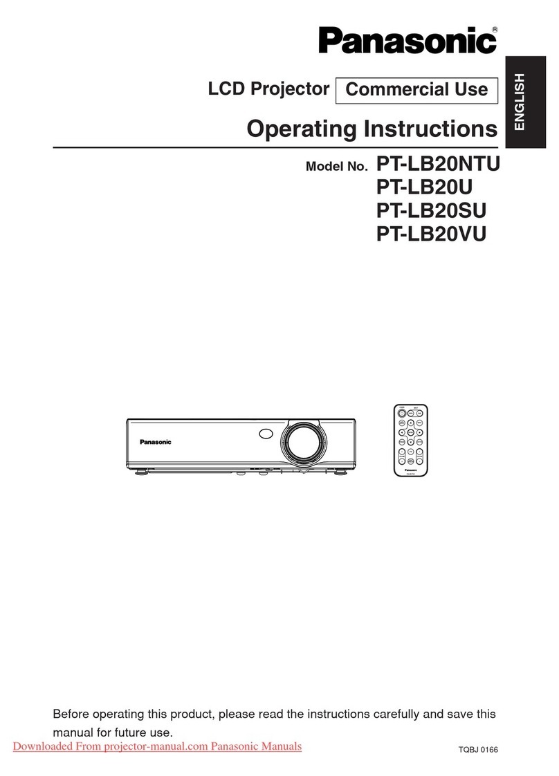
Photo 5 shows an installation example using
specially made hanging pipes as low-ceiling
brackets.
Although wobble prevention is effected using
wires, a projected image may still sometimes
wobble due to building vibration. Periodic
maintenance is carried out to maintain edge
blending by adjusting lens shift etc.
Photo 5
3) Considerations when mounting and adjusting with a hanging bracket
~Problems such as shifting of edge blending after installation and adjustment, and going out
of adjustment less than a week after readjustment are often a result of problems in the
adjustment of the hanging bracket and temperature drift.
The points to keep in mind during adjustment are described below.
~The adjustment of installation angle of a hanging bracket is described on the next page
using ET-PKD75S as an example.
When fastening bolts while adjusting each image contour, the following cautions should be
heeded to avoid metal distortion caused by fastening imbalance.
When the projected image is shifted to the left or right against the screen ? Fasten the
four hexagonal nuts on the hanging bolts on the topside of the attachment plate with
uniform torque.
When the projected image is shifted vertically from the screen ? Loosely fasten the two
hexagonal bolts for vertical angle adjustment at the left and right and adjust the projection
angle by moving the backside of the projector vertically. Then, fasten the left and right
hexagonal bolts alternately little by little to achieve uniform fastening torque.
When the projected image is tilted to the left or right, loosely fasten the hexagonal bolts
for left-right angle adjustment (3 places each on the front and back) and adjust the tilt of
the projector with these bolts, and then fasten the bolts at the front and back alternately in
a diagonal line little by little to finally achieve uniform torque at the end of adjustment.
~After turning the lamp power on, the projector generates some temperature drift through
the operation of lens shift and focusing. Adjustment should be performed after stabilizing
the projector for at least 30 minutes after turning the lamp power on. Lens shift operation
should be performed by operating with the remote control in one direction and then
pressing the opposite direction button momentarily to release the force applied to the lens
shift gear. After all adjustments have been made, the projector should be lightly shaken to
make sure that the position does not shift.
- 8 -
Adjustment of Installed Angle
zThe hanging bracket is equipped with an adjustment function to correct any shift of the projected
image in the left-right and top-bottom directions as well as tilt in the left-right angle against the
screen. The projector should be adjusted so that the lens centerline is perpendicular to the screen
surface.
zThe following adjustments should be made after projecting an image with the projector and
temporarily adjusting the image size with the zoom and focus with the focus ring. (Please refer to
the projector user manual for zoom and focus adjustment)
9
When the projected image is shifted to the left or right against the screen
When the projected image is tilted to the left or right
(1) Loosen the four hexagonal nuts on the
hanging bolts on the attachment plate, and
move the projector in the left and right
directions to align the image center with the
screen center.
(2) After confirming the alignment of the image,
securely fasten the hexagonal nuts on the
bolts.
Hexagonal nut
for securing the
topside hanging
bolt
Adjustable in
this range
When the projected image is shifted to the top or bottom against the screen
(1) Loosen the hexagonal bolts (2 places on
each side of left and right) that secure the
attachment plate and angle adjustment
bracket, and move the back of the projector
up and down to align the projected image
with the screen.
(2) After confirming the image position,
securely fasten the hexagonal bots.
zDo not remove the hexagonal bolts that
secure the attachment plate and angle
adjustment bracket. Removing the bolts
may cause the projector to drop.
Request
Adjustable
in this
range
5°
upward
5°
downward
Loosen the
hexagonal bots
(2 placed on
each side of
left and ri
g
ht
)
zDo not remove the hexagonal bolts that
secure the projector attachment plate
and angle adjustment bracket. Removing
the bolts may cause the projector to
drop.
Request
(1) Loosen the hexagonal bolts (3 places each on the
front and back) that secure the projector
attachment plate and angle adjustment bracket,
and adjust the tilt of the projector body in order to
achieve the correct projection angle.
(2) After confirming no tilt, then securely fasten the
hexagonal bolts.
Loosen the
hexagonal bots
(3 places each
on the front
and back
)
Adjustable in
this range
Notice zWhen the projected image has trapezoid distortion after adjusting the installed
angle, the positional relationship between the screen and projector is incorrect.
Check each dimension by referring to the “Installation work dimensions” on page 4.
(3) Considerations for the System Design of the Signal Delivery System
1) Enter the same signal into each projector
The projector input signal for edge blending needs to be equalized using a distributor
Adjustment data for each input signal needs to be registered in the projector memory.
2) When projecting individual images in addition to edge-blended images
When registering individual images in the memory, create a sub-memory, and adjust the
image to a smaller size to avoid image overlapping. (3-chip DLP type: Max. 96 memories,
1-chip DLP type: Max. 8 memories). At this time, the image size can be made greater without
changing the aspect ratio by moving the image contour position with the help of the raster
position function. Raster position adjustment, therefore, needs to be made in order to avoid
image overlapping.
3) Considerations when unifying multiple input signals into a unified frequency using a
scan converter
When multiple units of personal computers are connected to a single set of projectors, even
the same XGA signal is slightly different for each PC in terms of the signal level, phase,
displayed area etc, and edge blending needs to be adjusted every time the PC is changed.
A scan converter unifies multiple output signals into a single type and the amount of
registration into the projector memory is much reduced.
~Considerations for setting up a multi-scan converter
Setting up an output resolution of a multi-scan converter according to the DMD resolution of
the projector
Example: D7700 (1400 dots x 1050 dots)
Unifying the output signal level, image enlargement rate, image shift etc of a multiple
number of multi-scan converters
Default output setting is desirable.
Slight variation exists in the dot clock and phase of each multi-scan converter.
For each pair of a projector and multi-scan converter, the dot clock of the projector needs to
be adjusted.
In this case, the dot clock of the projector is adjusted by delivering the internal test pattern of
the multi-scan converter. Connection with DVI cable is recommended.
Photo 6 shows the condition of out-of-dot
clock in the projector on the left-hand
side.
An out-of-dot clock condition with a
multi-scan converter even makes the hue
and brightness change.
Photo 6
- 10 -