manuals.online logo
Brands
  1. Home
  2. •
  3. Brands
  4. •
  5. Payne
  6. •
  7. Furnace
  8. •
  9. Payne PG9MAA User manual

Payne PG9MAA User manual

Other manuals for PG9MAA

4

Other Payne Furnace manuals

Payne PG8MAA Series G User manual

Payne

Payne PG8MAA Series G User manual

Payne PG8HAA User manual

Payne

Payne PG8HAA User manual

Payne PG9MAB User manual

Payne

Payne PG9MAB User manual

Payne 394gad User manual

Payne

Payne 394gad User manual

Payne PG8DAA User manual

Payne

Payne PG8DAA User manual

Payne PG8JAA042090AAJA User manual

Payne

Payne PG8JAA042090AAJA User manual

Payne PY3G Series User manual

Payne

Payne PY3G Series User manual

Payne PG92SCS Operation manual

Payne

Payne PG92SCS Operation manual

Payne C Series Installation manual

Payne

Payne C Series Installation manual

Payne PG92ESA Guide

Payne

Payne PG92ESA Guide

Payne F Series Instructions and recipes

Payne

Payne F Series Instructions and recipes

Payne PG95 Guide

Payne

Payne PG95 Guide

Payne PG96VTA Guide

Payne

Payne PG96VTA Guide

Payne PG8HAA Guide

Payne

Payne PG8HAA Guide

Payne PG9YAB Series Original instructions

Payne

Payne PG9YAB Series Original instructions

Payne 394G User manual

Payne

Payne 394G User manual

Payne C Series Guide

Payne

Payne C Series Guide

Payne Gas Furnace User manual

Payne

Payne Gas Furnace User manual

Payne PG9MAA User manual

Payne

Payne PG9MAA User manual

Payne PG80ESAA Guide

Payne

Payne PG80ESAA Guide

Payne PG9MXA Series Instructions and recipes

Payne

Payne PG9MXA Series Instructions and recipes

Payne PG8MVA User manual

Payne

Payne PG8MVA User manual

Payne PG9MAB User manual

Payne

Payne PG9MAB User manual

Payne PG9YAA User manual

Payne

Payne PG9YAA User manual

Popular Furnace manuals by other brands

Unitary products group AHV8 UH installation manual

Unitary products group

Unitary products group AHV8 UH installation manual

VERDER CARBOLITE GERO RHF 14/8 Installation, operation and maintenance instructions

VERDER

VERDER CARBOLITE GERO RHF 14/8 Installation, operation and maintenance instructions

Tempstar B Series Service and technical support manual

Tempstar

Tempstar B Series Service and technical support manual

Carrier Performance 59SP5A Installation, start-up, operating and service and maintenance instructions

Carrier

Carrier Performance 59SP5A Installation, start-up, operating and service and maintenance instructions

Armstrong EG7H SERIES Installation and maintenance instructions

Armstrong

Armstrong EG7H SERIES Installation and maintenance instructions

NANOE Zetasinter Operation manual

NANOE

NANOE Zetasinter Operation manual

SUPREME FEM10-M2301CM-A Installation instructions and homeowner's manual

SUPREME

SUPREME FEM10-M2301CM-A Installation instructions and homeowner's manual

Johnson Controls TM9T User's information manual

Johnson Controls

Johnson Controls TM9T User's information manual

Fluke 9118A user manual

Fluke

Fluke 9118A user manual

Lennox EL195UHE Elite Series Unit information

Lennox

Lennox EL195UHE Elite Series Unit information

Intertherm M7RL Series user manual

Intertherm

Intertherm M7RL Series user manual

HDG Pelletmaster 15 Operation manual

HDG

HDG Pelletmaster 15 Operation manual

Nortek MG2S Series installation instructions

Nortek

Nortek MG2S Series installation instructions

VERDER CARBOLITE GERO ABF 8/28 Installation, operation and maintenance instructions

VERDER

VERDER CARBOLITE GERO ABF 8/28 Installation, operation and maintenance instructions

Goodman GMV9 Installation & operating instructions

Goodman

Goodman GMV9 Installation & operating instructions

SUPREME SUP10-M2301C Installation instructions and homeowner's manual

SUPREME

SUPREME SUP10-M2301C Installation instructions and homeowner's manual

Dettson AMT400B34-SM1PMA Installation instructions and homeowner's manual

Dettson

Dettson AMT400B34-SM1PMA Installation instructions and homeowner's manual

Evcon DGD 60 MBH installation instructions

Evcon

Evcon DGD 60 MBH installation instructions

manuals.online logo
manuals.online logoBrands
  • About & Mission
  • Contact us
  • Privacy Policy
  • Terms and Conditions

Copyright 2025 Manuals.Online. All Rights Reserved.

Mn )n Manual
4-WAY MULTIPOISE
FIXED-CAPACITY DUAL-VENT
CONDENSING GAS FURNACE
SIZES 040 THRU 140
PG9MAA
Series F
As all F\ERGY STARX, Panner. Payne
Heating and ( ooling has determined that
this ploduct meets the E\'ERGY STAR_
guidelmes fbl energy efficiency
NOTE: Read the entire instruction manual before starting the installation
This symbol --> indicates a change since the last issue,
INDEX
Page
SAFETY CONSIDERATIONS 2
(LEARAN(ES TO COMBUSTIBLES 3
DIMENSIONAL DRAWING 4
(ODES AND STANDARDS 6
ELECTROSTATIC DIS(HARGE (ESD) PRECAUTIONS 7
INTRODU( TION 7
APPLICATIONS 8
General 8
Upflow Applications 8
Downflow Applications .......................................................................................................................................................................................... 10
Horizontal Lek (Supply=Air Discharge) Applications .......................................................................................................................................... 12
Horizontal Right (Supply-Air Discharge) Applications ........................................................................................................................................ 13
LO(ATION ................................................................................................................................................................................................................. 16
General .......................................................................................................... 16
Furnace Location Relative to Cooling Equipment ................................................................................................................................................ 17
Location wit}*Respect to Combustion and (irculating Air Requirements ................................................... 18
Hazardous Locations ................................................................................................. 18
AIR FOR COMBE STION AND VENTILATION ............................................................................ 19
INSTALLATION ..................................................................................................... 22
Leveling Legs (If Desired) ............................................................................................. 22
Installation In L pflow or Downflow Applications ......................................................................... 22
Installation In Horizontal Applications ................................................................................ 24
Air Ducts ........................................................................................................ 24
General .............................................................................................................................................................................................................. 24
Ductwork Acoustical Treatment ....................................................................................................................................................................... 24
Supply Air (onnections .................................................................................................................................................................................... 25
Form: tM-PG9M-10 Cancels: tM-PG9M-09 Printed in U.S.A. 2-05 Catalog No. 53PG-9M29
SAFETYCONSIDERATIONS
z_ CAUTION:FURNACERELJAB_LITYHAZARD
improperinstallationormisapplicationoffurnacemayrequireexcessiveservicingorcauseprematurecomponentfailure,
Applicationofthisfurnaceshouldbeindoorswithspecia!attentiongiventoventsizingandmaterial,gasinputrate,airtemperature
rise,unitleveling,andunitsizing.
z_ WARNmNG:FIRE,EXPLOSBON,ELECTRICALSHOCKANDCARBONMONOXIDEPOISONINGHAZARD
Failuretofollowthiswarningcouldresultinelectricalshock,fire,personaliniury,ordeath.
Improperinstallation,adjustment,alteration,service,maintenance,orusecancausecarbonmonoxidepoisoning,explosion,fire,
electricalshock,orotherconditionswhichmaycausepersonalinjuryorpropertydamage.Consultaqualifiedinstaller,serviceagency,
localgassupplier,oryourdistributororbranchforinformationorassistance.Thequalifiedinstalleroragencymustuseonly
factory-authorizedandlistedkitsoraccessorieswhenmodifyingthisproduct.
Installing and servicing heating equipment can be hazardous due to gas and electrical components. Only trained and qualified personnel should
install, repair, or service heating equipment. Untrained personnel can per_brm basic maintenance J?unctions such as cleaning and replacing air
_]lters. All other operations must be perI:bmaed by trained service personnel. When working on heating equipment, observe precautions in literature,
on tags, and on labels attached to or shipped with unit and other safety precautions that may apply.
2
• This forced air furnace is equipped for use with natural gas at altitudes 0 - 10,0001:[ (0 - 3,050m), except 140 size furnaces are only approved for altitudes 0 - 7,000 ft.
(0 - 2,135m).
o An accessory kit, supplied by the manufiacturer, shall be used to convert to propane gas use or may be reduired for some natural gas applications.
e This furnace is for indoor installation in a building constructed on site. This furnace may be installed in a manufactured (nTabile) home when stated on rating plate and
using factory authorized kit..
o Thle furnace may be installed on combustible flooring in alcove or closet at _"ainimum Inches Clearar_ce To Combustible Construction as described below.
® This furnace requires a special venting system. Refer to the installation instructions for parts list and method of installation. This furnace is for use with schedule-40 PVC,
PVC-DV_v', CPVC, or ABS-D_AN pipe, and must not be vented in common with other gas-fired appliances. Construction through which vent!air intake pipes may be
installed is maximum 24 inches (60Omm), minimum 3/4 inches (19 mm) thickness (including roofing materials).
• Cetta foumaise A air pule6 est 6quip@e pour utilisatlen avec gaz natural et altitudes comprises entre 0 - 3,050m (0 - 10,000 pi),except6 queles fournaises de 140 taille
sent pour altitudes comprises entre 0 - 2,135m (0 - 7,000pi).
• Utilleer une trousse de conversion, foumle per le fiabrleant, pour passer au gaz propane ou pour certaines instNlations au gaz naturel.
o Cetta foumaise A air pule6 est pour installation A Hnt6rieur dans un bgtiment construit sur place. Cetta foumaise _ air pulse peut 6tre instalk_e dans une maison
pr6fiabdqu6e (maison mobile) si prescrit par la plaque signal_,tique et si I'on utilise une trousse specifi6e par le fabrleant.
¢ Cette foumaise peut 6tre install6e sur un plancher combustible dans un enfoncement ou un placard en observa!]t los D_gagement Minimum EB Pouces Avec
EI6rnents De Construction Combustibles.
• Cetta fournaise n6cessita un systeme d'6vacuatlen sp6cial. La m6thode d"installation et la Ilete des pi@ces n6cessaires figurent darts los instructions d'installation. Cette
foumalee doit s'utilleer avec la tuyautarie des nomenclatures 40 PVC, PVC-DWV CPVC ou ABS-DWV et ella ne peut pas 6tre ventil6e conjointment avec d'autres
appereils _ gaz. Epeleseur de la construction au travers de laquelle il est possible de faire passer los tuyaux d'a6ratlen (admission/6vacuation): 24 po (600 ram)
maximum, 3/4 po (19mm) minimum (y compris la toiture).
For upflow and dewnflow applications, furnace must be installed level, or pitched within 1/Z' of level. For a MIN 1/4" TO 1/2" MAX
horizontal application, the furnace must be pitched minimum 1/4" to maximum of 1/2" forward for proper
drainage. See Installation Manual for iMPORTANT unit supper[ details on horizontal applications.
Pour des applications de flux ascendant et descendant, le fournalee deit 6b_ install@e de niveau ou inclin6e
pes plus de 1/Z' du niveau. Pour une application horizontale, la foumaise doit _,tre indin6e entre minimum
1/4' et maximum 1/Z' du niveau pour le drainage appropri& En cas d'installation en position horizontale,
censultar lea renseignercents IM PORTANTS sur le support dans le manuel d'installation. HORIZONTAL
NININUM INCHES CLEARANCE TO COMBUSTIBLE CONSTRUCTION
ALL POSITIONS:
Minimum front clearance for service 24 inches (610ram).
? 1- 140 size furnaces require 1 inch back clearance to combustible materials.
DOWNFLOW POSITIONS:
1- For installatiorl on combustible floors only when installed on spedal base No. KGASB0201ALL
Coil Assembly, Part No. CD5 or CK5, or Coil Casing, Part No. KCAKC.
HORIZONTAL POSITIONS:
Line corRaet is permissible only between lines formed by intersections of top and two sides d
furnace jacket, and building joists, studs, or framing.
§ Clearance shown is for air inlet and air outlet ends.
O 120and 140 size fumaces require 1 inch bottom clearance to combustible materials.
DEGAGEMENT MINIMUM EN POUCES AVEC ELEMENTS DECONSTRUCTION COMBUSTIBLES
POUR TOUS LES POSITIONS:
Degagement avant minimum de 610mm (24 po) pour I'entretien.
1- 1- Pour les fournaises de 140 taille, 1 1_ (25mm) d6gagerT_ent des matedaux combustibles set
requis au-ardere.
POUR LA POSITION COURANT DESCENDANT:
1- Pour Hnstallation sur le plancher combustible seulerT_nt quand on utilise la base sp_ciale, piece
n ° KGASB0201ALL rensemble serpentin, pi6ce n ° CD5 eu CK5, eu le carter de serpentin,
pi6ce n ° KCAKC.
POUR LA POSITION HORIZONTALE:
Le contact n'est permis q0entre les lignes forrnees par les intersections du deseus et des
deuxc6tes de la chemise de la fournaise, et des solives, des montants eu de la charpente du
batiment.
§ La distance indiquee concerne I'extr@mite du tuyau d'arfivee d'air et I'extremite du tuyau de sortie
d'air.
Pour les fournaises de 120 et 140 taille, 1 po (25ram) degagement des materiaux cembusitbles
set requis au_desseus.
This furnace is approved for U PFLOW, DOWN FLOW and
HORIZONTAL installations.
Cette foumaise est approuv¢e pour I'installatlen HORJZONTALE
et la drculation d'atiVERS LE HAUT et VERS LE BAS.
Clearance arrows J_gagement
do not change with ne c.hange pas avec
furnace orientation, I'0rientation de la
g_n@ateur d'air d-_aud,
Vent dearance to
combustibles 0".
Clearance in indqes 0 (po) Dg_Jagement
D@gagement (po). d'@vent avec combustibles.
328066-201 REV. B LIT TOP
J
A04110
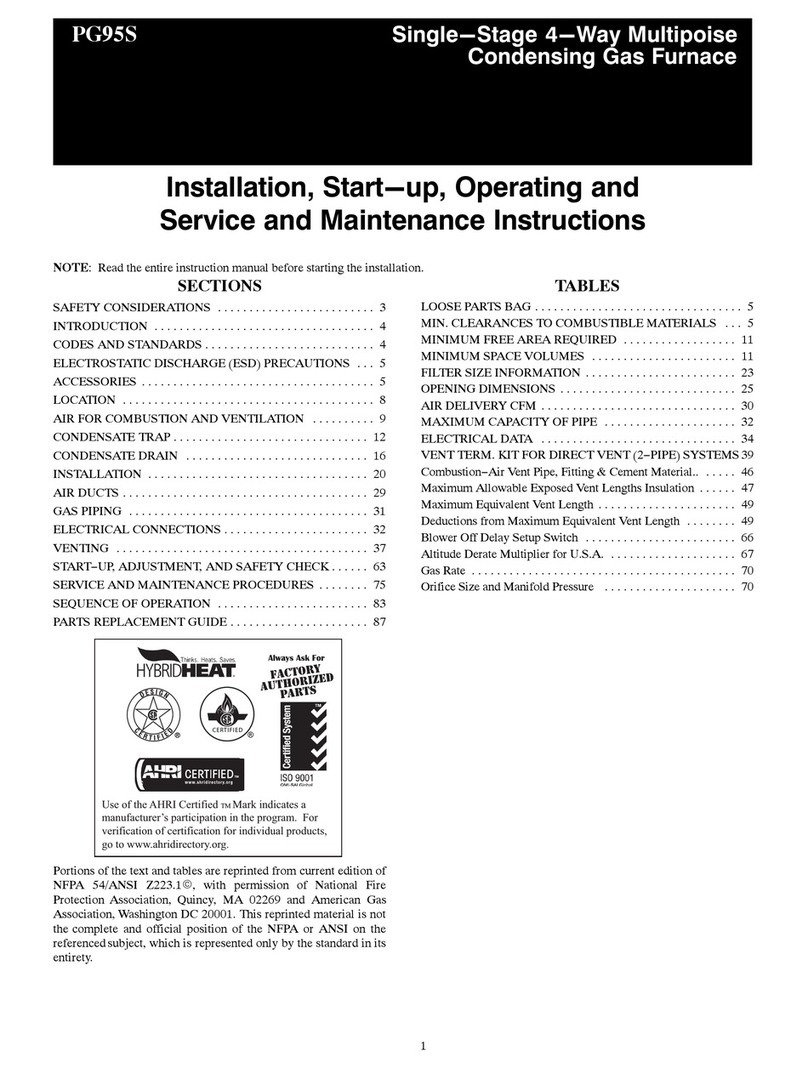
Fig. !--Clearances to Combustibles
These instr_ctions cover the minimum requirements and conform to existing national standards and sa_ty codes. In some instances, these
instructions exceed certain local codes and ordinances, especially those that may not have kept up with changing residential cop.strtlction practices.
We require these instructions as a minimum for a safe installation.
Wear safety glasses and work gloves. Have a fire extinguisher available during startoup and adjustment procedures and service calls.
Z_ CAUTION: CUT HAZARD
Failure to follow this caution may result in personal injury.
Sheet metal parts may have sharp edges or burrs, Use care and wear appropriate protective clothing and gloves when handling parts,
Recognize safety in_brmation This is the safety-alert symbol Z_x. When you see this symbol on the unit and in instructions or manuals, be alert
to the potential for personal injury.
Understand these signal words DANGER, WARNING, and (AUTION. These words are used with the sa_Ytyoalert symbol. DANGER identifies
the most serious hazards which wi_]l result in severe personal injury or death. WARNING signifies hazards which could result in personal ir_jury
or death. CAUTION is used to identi_}g unsafc practices which may result in minor personal injury or product and property damage. NOTE is used
to highlight suggestions which wil_ result in enhanced installation, reliability, or operation.
The PGgM Multipoise (ondensing Gas-Fired Furnaces are (SA (fermerly AGA and CGA) designocertified J_br natural and propane gases (see
_imaace rating plate) and for installation in alcoves, attics, basements, closets, utility rooms, crawlspaces, and garages. The ftmaace is
_hctory-shipped f_r use with natural gas. A (SA listed gas conversion kit is required to convert furnace _br use with propane gas.
See Fig. 1 for required clearances to combustibles.
3
1k
.... ,,f +
<o z z _i i
.r_ <o ,¢. z '
_ _ i'_ _ i
i i
-÷f" -€-_
b
%z
_2
S
c_
<
_o_ c_
<F=O
z_u. <:oz
oc_z
OZ wi $
ul
o
Z
o_
<(
N
Z
I
i
i
i
i
i
i
i
i
i
i
i
i
i
I
i
i
i
i
i
i
i
i
i
i
i
i
i0D
iP-
i
i
i
i
i
i
I
i
i
i
i
i
i
i
i
i
i
i
i
i
I
i
i
i
i
i
i
i
i
i
i
i
i
i
io
i0
i
I
i
i
i
i
i
i
i
i
i
i
i
i
8
(x!
z
8
.2
@
@
B
i
d_ E
o
Z
o_
4
AIRFLOW
O-
] _ HORIZONTAL
LEFT
AIRFLOW
©
AIRFLOW
Fig. 3--Multipoise Orientations
\
HORIZONTAL [_
RIGHT
AIRFLOW
A93041
Maintain a l-in. clearance ti'om comhustible materials to supply air ductwork %r a distance of 36 inches horizontally from the fltrnace. See NFPA
90B or local code for fl_rther requirements.
These furnaces SHALL NOT be installed directly on carpeting, tile, or any other combustible material other than wood flooring. In downflow
installations, factolw accessory floor base MUST be used when installed on combustible materials and wood flooring. Special base is not required
when this fllmace is installed on manufacturer's (oil Assembly Part No. (D5 or CK5, or when (;oil Box Part No. KCAKC is used.
The PGgM 040 through 120 size units are CSA (fom_erly CGA and AGA) designocertified for use in manufi_cmred (mobile) homes when filctory
accessow conversion kit is used. The 140 size unit is NOT design-certified for use in manufactured (mobile) homes. These t'umaces are suitable
f'_r installation in a structure built on site or a manufactaIed building completed at final site. The design of this flmaace line is NOT CSA
design-certified for installation in recreation vehicles or outdoors.
--> This t'urnace is designed for continuous return-air n_ininmm temperature of 60_>F db or intermittent operation down to 55°F db such as when used
with a night setback thermostat. Returnoair temperature must not exceed 80_F db. Failure to follow these return-air limits may afflict reliability
of heat exchangers, motors and controls. (See Fig. 4.)
These t:arnaces are shipped with the drain and pressure tubes connected for UPFLOW applications. Minor modifications are required when used
in DOW_FLOW, HORIZONTAL RIGHT, or HORIZONTAL LEFT (supply-air discharge direction) applications as shown in Fig. 3. See details
in Applications section.
--> Install this t'urnace only in a location and position as specified in LOCATION and INSTALLATION sections of these instructions.
--> Combustion products must be discharged outdoors. (onnect this flul_ace to an approved vent system only, as specified in the Combustion Air and
Vent piping sections of these instructions.
--€ Never test fbr gas leaks with an open flame. Use a commercially available soap solution made specifically for detection of leaks to check all
connections as specified in the GAS PIPING section of these instructions.
--> Always install the fimaace to operate within the furnace's intended rise range with a duct system which has an external static pressure within the
allowable range as specified in the SET TEMPERATURE RISE section of these instructions.
--> When a t'urnace is installed so that supply ducts carry air circulated by the fl/mace to areas outside the space containing the fl/mace, the return
air shall also be handled by ducts sealed to the fl/mace casing and tem_inating outside the space containing the t:umace.
--> A gas-fired furnace for installation in a residential garage must be installed as specified in the Hazardous Locations section of these instn/ctions.
--> The t'urnace is not to be used for temporaw heating of buildings or structures under construction unless the fl/mace installation and operation
complies with the first CAUTION in the LOCATION section of these instructions.
FRONT
MAX80°F
MIN60°F
--> Fig, 4--ReturnoAir Temperature
5
A05004
BLOWERSHELFT-FURNACE
_DOOR
CONDENSATE \
TRAP (INSIDE) X I
FIELD --_
DRAIN
CONN
TUBE LOCATION
CONDENSATE TRAP-
DRAIN TUBE LOCATION
UPFLOW APPLICATIONS
i; CONDENSATE
TRA;uRNACE
SIDE/
261/4 1 /2
SIDE VIEW FRONT VIEW
DOWNFLOW AND ALTERNATE
EXTERNAL UPFLOW APPLICATIONS
_._ FURNACE
OOR
DRAIN
CONN
-- FURNACE
SIDE
I
¾
END VIEW FRONT VIEW
HORIZONTAL
APPLICATIONS
SLOT FOR SCREW --7
HORIZONTAL ]
APPLICATION ]
(OPTIONAL)I
Im !
'4
GUIDES
(WHEN USED)
//4OD
COLLECTOR BOX TO
TRAP RELIEF PORT
//2OD
INDUCER HOUSING
DRAIN CONNECTION
%OD
COLLECTOR BOX
DRAIN CONNECTION
7
SCREW HOLE FOR
UPFLOW OR DOWN-
FLOW APPLICATIONS
7/8 2(OPTIONAL)
2 //2-1N. PVC OR CPVC
FRONT VIEW SIDE VIEW
A93026
Fig, 5--Condensate Trap
7hose _:tlITlaces are shipped with the following materials to assist in proper furnace installation 7hose materials are shipped in the main blower
compartment
Installer Packet includes:
Installation Manual
Service Guide
User's Inibrmation Manual
Warranty Certificate
Loose Parts Bag includes:
Pressure tube extension
Collector box or condensate trap extension tube
Inducer housing &ain robe
1/2=in. CPVC street elbow
Drain tube coupling
Drain robe coupling grommet
Vent and combustion=air pipe support
Condensate trap hole [itler plug
Vent and combustion=air intake hole filler plug
Combustion-air pipe perforated disk assembly
Vent Pipe Extension (ONLY supplied with some _i/maces)
Quantity1
1
1
2
1
1
2
3
2
1
1
For accessow installation details, refer to accessow installation instructions
CODES AND STANDARDS
Follow all national and local codes and standards in addition to these instructions. The installation must comply with regulations of d-_e
serving gas supplier, local building, heating, plumbing, and other codes. In absence of local codes, the installation must comply with the national
codes listed below and all authorities having jurisdiction.
6
-->.
In the United States and Canada, %llow all codes and standards %r the %llowing:
PROCEDURE I--SAFETY
US: National Fuel Gas (7ode (NFGC) NFPA 54=2002/ANS1 Z223,1-2002 and the Installation Standards, Warm Air Heating and Air
Conditioning Systems ANSI NFPA 90B
CANADA: National Standard of Canada, Natural Gas and Propane Installation Code NSCNGPIC) CSA BI49 1-00
PROCEDURE 2--GENERAL mNSTALLAT]ON
US: NFGC and the NFPA 90B. FoI copies, contact the National Fire Protection Association Inc, Batterymarch Pail{, Quincy, MA 02269; or
_br only the NFGC contact the American Gas Association, 400 N. Capitol, N.W., Washington D( 20001
CANADA: NSCNGPIC. For a copy, contact Standard Sales, CSA International, 178 Rexdale Boulevard, Etobicoke (Toronto), Ontario, M9W
1R3, Canada.
A manu_hctured (Mobile) home installation must conform with the M_mz_acmred f_2)me ('on,strzlctio_ and &{/ely Standard, Tide 24 (TR, Part
32(_0, or when this standard is not applicable, the Standard for Mc_n_acnH'ed h2)me I_staHation (_Uanz(fi_etz_red f_%)me Sites, ('om_zznitie,s, and
5_.,t-L_,s), A.VhT,_\Z'S A225.1, and/or C.4_\;,_'hII-Z240, MH Serie,_' :'_lobi[e Homes
PROCEDURE a--COMBUSTION AND VENTILATION AiR
* US: Section 8.3 of the NFGC, Air fbr Combustion and Ventilation
* CANADA: Part 7 of the NSCNGPIC, Venting Systems and Air Supply for Appliances
PROCEDURE 4--DUCT SYSTEMS
* [S and CANADA: Air Conditioning Contractors Association (ACCA) Manual D, Sheet Metal and Air Conditioning Contractors National
Association (SMACNA), or American Society of Heating, Refl'igeration, and Air Conditioning Engineers (ASHRAE) 2001 Fundamentals
Handbook Chapter 34.
PROCEDURE 5--ACOUSTICAL LINING AND FIBROUS GLASS DUCT
* IS and CANADA: current edition of SMACNA, NFPA 90B as tested by UL Standard 181 _br Class I Rigid Air Ducts
PROCEDURE 6--GAS PIPING AND GAS PIPE PRESSURE TESTmNG
*/S: NFGC; chapters 5, 6, 7, and 12 and national plumbing codes
* CANADA: NSCNGPIC Part 3, 4, 5, A, B, E, and H.
NOTE: In the state of Massachusetts:
1. Gas supply comaections MUST be perfbrmed by a licensed plumber or gas fitter.
2. When flexible connectors are used, the nlaxinmm length shall not exceed 36 inches (915 ram).
3. When lever handle type manual equipment shutoff valves are used, they shall be T°handle valves.
4. The use of copper tubing _br gas piping is NOT approved by the state of Massachusetts.
PROCEDURE g--ELECTRiCAL CONNECTIONS
*LS: National Electrical Code (NEC) ANSINFPA 70-2002
* CANADA: Canadian Electrical Code CSA C22.1
ELECTROSTATIC DBSCHARGE (ESD) PRECAUTIONS
CAUTION: UNIT DAMAGE HAZARD
Failure to follow this caution may result in damage to unit components.
Electrostatic discharge can affect electronic components. Take precautions during furnace installation and servicing to protect the
furnace electronic control Precautions will prevent electrostatic discharges from personnel and hand tools which are held during the
procedure. These precautions will help to avoid exposing the control to electrostatic discharge by putting the furnace, the control, and
the person at the same electrostatic potential.
Disconnect all power to the furnace. Multiple disconnects may be required. DO NOT TOUCH THE CONTROL OR ANY WIRE
CONNECTED TO THE CONTROL PRIOR TO DISCHARGING YOUR BODY'S ELECTROSTATIC CHARGE TO GROUND.
2. Firmly touch a clean, unpainted, metal sur_i_ce of the fl_mace chassis which is close to the control Tools held in a person's hand during
grounding will be satisfactorily discharged.
3 After touching the chassis, you may proceed to service the control or connecting wires as tong as you do nothing that recharges your body
with static electricity (for example; DO NOT move or shuffle your feet, DO NOT touch ungrotmded objects, etc.).
4 If you touch ungrounded objects (recharge your body with static electricity), firmly touch a clean, unpainted metal sur_hce of the flul_ace
again befbre touching control or wires.
5 Use this procedure *\_r installed and uninstalled (ungrounded) fire, aces
6 Be[bre removing a new control fi'orn its container, discharge your body's electrostatic charge to ground to protect the conhol fl'orn damage.
If the control is to be installed in a [:urnace, fbllow items 1 through 5 be_bre bringing the control or yourself into contact with the fl/mace.
Put all used AND new contlols into containers before touching ungrounded objects.
7 An ESD smwice kit (available from commercial sources) may also be used to prevent ESD damage
7
PLUG
CAP
COLLECTOR BOX
DRAIN TUBE (BLUE
& WHITE STRIPED)
COLLECTOR BOX
TUBE (PINK)
TUBE (GREEN)
(MOLDED) DRAIN
TUBE (BEHIND
COLLECTOR BOX
DRAIN TUBE)
DRAIN TUBE (BLUE)
FIELD-INSTALLED
FACTORY-SUPPLIED
DRAIN TUBE
COUPLING (LEFT
DRAIN OPTION)
FIELD-INSTALLED
FACTORY-SUPPLIED
DRAIN TUBE
FACTORY-SUPPLIED
_/2-1NCPVC STREET
ELBOWS (2) FOR
LEFT DRAIN OPTION
FIELDqNSTALLED
FACTORY-SUPPLIED
DRAIN TUBE
COUPLING (RIGHT
DRAIN OPTION) A00288
Fig. 6--Factory-Shipped Upflow Tube Configuration
(Shown With Blower Access Panel Removed)
PLUG
CAP
COLLECTOR BOX
DRAIN TUBE (BLUE
& WHITE STRIPED)
COLLECTOR BOX
TUBE (PINK)
COLLECTOR BOX --
TUBE (GREEN)
COLLECTOR BOX --
DRAIN TUBE (BLUE)
CONDENSATETRAP __
INDUCER
HOUSING
DRAIN TUBE
(VIOLET)
O O
A00289
Fig. 7--ARernate Upflow Tube Configuration and
Trap Location
INTRODUCTION
The model PG9M 4-way multipoise, Gas-Fired, Catego UIV, direct=xent and non=direct vent, condensing f_/rnace is axailable in model sizes
ranging in input capacities of 40,000 to 138,000 Btuh
Z_ CAUTION: MINOR PROPERTY DAMAGE
Failure to follow this caution may result in minor property damage.
Local codes may require a drain pan under entire furnace and condensate trap when a condensing furnace is used in an attic
application or over a finished ceiling.
APPLICATIONS
PROCEDURE I--GENERAL
Some assembly and modifications are required %r [bmaces installed in any of the 4 applications shown in Fig, 3 All drain and pressure robes are
connected as shown in Fig, 6 See appropriate application instructions fbr these procedures
PROCEDURE 2--UPFLOW APPUCATIONS
An upflow f_/mace application is where f_/rnace blower is located below combustion and contlols section of furnace_ and conditioned air is
discharged upwards,
A. Condensate Trap Location (Factory-Shipped Orientation)
_he condensate tlap is factory installed in the blower shelf and fi!ctory connected for UPFLOW applications. A factow-supplied tube is used to
extend the condensate trap &ain connection to the desired furnace side _br field drain attachment See Condensate Trap Tubing (Factory°Shipped
Orientation) section for drain tube extension details, (See Fig. 5,)
B, Condensate Trap Tubing (Factory-Shipped Orientation)
NOTE: See Fig. 6 or tube routing 1abet on main furnace door to confirm location of these tubes,
g
-->
1 Collector Box Drain, Inducer Housing Drain, Relief Port, and Pressure Switch Tubes
These tubes should be fi_ctow attached to condensate trap and pressure switch ready for use in UPFLOW applications These tubes can be
identified by their connection location and also by a color label on each tube These tubes are identified as follows: collector box drain robe
(blue label), inducer housing drain robe (violet label or molded), relief port robe (green label), and pressure switch robe (pink label).
2 (ondensate Trap Drain Tube
The condensate trap drain connection must be extended for t_eld attachment by doing the following:
a. Determine location of field drain connection. (See Fig. 2or 60
NOTE: If internal filter is used, drain tube should be located to opposite side of casing t'rom remm duct attachment to assist in filter removal
b Remove and discard casing drain hole plug button fiom desired side
c. Install &ain robe coupling grommet (factory-supplied in loose parts bag) in selected casing hole
d Slide &ain robe coupling (factory=supplied in loose parts bag) through grommet ensuring long end of coupling fitces blower
e. (ement 2 fi_ctory=supplied li2-in stIeet CPV( elbows to the rigid drain tube connection on the condensate tlap (See Fig. 6) These
elbows must be cemented together and cemented to condensate trap drain connection.
NOTE: Failure to use CPVC elbows may allow drain to kink and prevent &aining.
f (onnect larger diameter drain robe and clamp (fitctory=supplied in loose parts bag) to condensate t_ap and clamp securely.
g Route robe to coupling and cut to appropriate length.
h Attach tube to conpling and clamp securely
C. Condensate Trap Location (ARernate Upflow Orientation)
An alternate location for the condensate trap is the teA-hand side of casing (See Fig. 2 and 7.)
NOT_=: It" the alternate tet't=hand side of casing tocation is used, the factow-connected drain and retief port robes must be disconnected and
modified _br attachment. See Condensate Trap Tubing (Alternate I pflow Orientation) section for tubing attachment
To relocate condensate tlap to the left=hand side, perfbm_ the following:
1 Remove 3 robes connected to condensate trap
2 Remove trap from blower shelf by gently pushing tabs inward and rotating tlap.
3 Install casing hole filler cap (tlactou=supplied in 1cone parts bag) into blower shelf hole where trap was removed.
Z_x WARNING: CARBON MONOXIDE POmSONING HAZARD
Failure to fo!low this warning could result in personal iniury or death,
Casing hole filler cap must be instal!ed in blower shelf hole when condensate trap is relocated to prevent combustion products being
drawn in from appliances in the equipment room,
4 Install condensate trap into left-hand side casing hole by inserting robe connection stubs through casing hole and rotating until tabs snap
into locking position
5 Fill unused condensate trap casing holes with plastic filler caps (factor-supplied in loose parts bag).
D, Condensate Trap Tubing {Alternate Upf[ow Orientation)
NOTE: See Fig 7 oi" tube routing label on main faInace door to confirm location of these robes
1. Collector Box Drain Tube
Connect collector box drain tube (blue label) to condensate trap.
NOTE: On 17-1/2-in. wide fuo'mces ONLY, cut robe between corn/gated sections to prevent kinks fi'om occurring.
2. Inducer Housing Drain Tube
a. Remove and discard LOWER (molded) inducer housing &ain robe which was previously connected to condensate trap.
b. Use inducer housing drain extension robe (violet label and factory=supplied in loose parts bag) to connect LOWER inducer housing drain
connection to the condensate trap
c. Determine appropriate length, cut, and connect robe.
d. Clamp robe to prevent any condensate leakage.
3. Relief Port Tube
a. Connect relief port tube (green label) to condensate trap.
b. Extend this robe (if required) by splicing to small diameter robe (factory=supplied in loose parts bag).
c. Determine appropriate length, cut, and connect robe.
E. Condensate Trap Field Drain Attachment
Refer to Condensate Drain section t\_r recommendations and procednIes
g. Pressure Sw{tch Tub{rig
The LOWER collector box pressure robe (pink label) is factor- connected to the pressure switch and should not require any modification
NOTE: See Fig. 6 or 7 or robe ronting label on main furnace door to check _br proper connections.
9
DRAIN TUBE (BLUE)
PLUG
COLLECTOR BOX --'-_
TUBE (GREEN)
COLLECTOR BOX
EXTENSION TUBE
COLLECTOR BOX "_
TUBE (PINK)
DRAIN TUBE (BLUE
& WHITE STRIPED)
EXTENSION TUBE
TRAP
]NDUCER HOUSING'
DRAINTUBE(VIOLET)
G,
Fig. 8--Downflow Tube Configuration
(Left-Hand Trap Installation)
O O
©
/f'-- PLUG
F COLLECTOR BOX
DRAIN TUBE (BLUE)
F COLLECTOR BOX
TUBE (PINK)
COLLECTOR BOX
TUBE (GREEN)
COLLECTOR BOX
EXTENSION TUBE
COLLECTOR BOX
DRAIN TUBE (BLUE
& WHITE STRIPED)
COLLECTOR BOX
EXTENSION TUBE
iNDUCER HOUSING
"_ DRAIN TUBE
F (VIOLET)
I_ CONDENSATE
_1 TRAP
_=== COLLECTOR BOX
EXTENSION
DRAIN TUBE
COUPLING
A00262
Fig. 9--Downflow Tube Configuration
(Right-Hand Trap Installation)
Upper Collector Box and Inducer Housing (Unused) Drain Connections
UPPER COLLECTOR BOX DRAIN CONNECTION
A00296
Attached to the l_ PPER collector box drain connection is a _ctow=installed corrugated, plugged robe (blue and white striped label). This tube is
plugged to prevent condensate leakage in this application. Ensure this robe is plugge&
NOTE: See Fig. 6 or 7or robe routing label on main f_lrnace door to check tbr proper connections.
UPPER INDUCER HOUSING DRAIN CONNECTION
Attached to the UPPER (unused) inducer housing &ain connection is a cap and clamp. This cap is used to prevent condensate leakage in this
application. Ensure d-ds connection is capped.
NOTE: See Fig. 6 or 7 or robe routing label on main fi/mace door to ciaeck [br proper connections.
H. Condensate Trap Freeze Protection
Refer to (ondensate Drain Protection section _br recommendations and procedures
PROCEDURE 3--DOWNFLOW APPLICATIONS
A downt]ow fmnace application is where farnace blower is located above combustion and controls section of furnace, and conditioned air is
discharged downwards.
A. Condensate Trap Location
7he condensate trap must be removed f_'om the factory-installed blower shelf location and relocated in selected application location as shown in
Fig. 2, 8, or 9.
To relocate condensate trap fi'om the blower shelf to desired location, perfbm_ the following:
1. Remove 3 tubes connected to condensate trap.
2. Remove trap flora blower shelf by gentty pushing tabs inward and rotating trap
3. Install casing hole filler cap (factouosupplied in loose parts bag) into blower shelf hole where trap was removed
---> z_ WARNING: CARBON NONOXIDE POISONING HAZARD
Failure to follow this warning could result in personal injury or death,
Casing hole filler cap must be installed in b!ower shelf hole when condensate trap is relocated to prevent combustion products being
drawn in from appliances in the equipment room.
4. Install condensate trap into left=hand side casing hole by inserting tube connection stubs through casing hole and rotating until tabs snap
into locking position,
5. Flit unused condensate trap casing holes with plastic f_ller caps (fSctory°supplied in toose parts bag)
i0