Phoenix MicroATX Express User manual

+
Phoenix MicroATX Express
Motherboard
Installation Guide

StockCheck.com
Downloaded from StockCheck.com

Introduction
Table of Contents
Introduction ........................................................................................ IV
Chapter 1 Pre-Configuration ....................................................1
Step 1 Setting the Jumpers 2
Jumper Locations............................................................................................................................... 3
CMOS Reset ........................................................................................................................................ 4
ATA-Disk Connector Voltage Selection ...........................................................................................4
RS422/RS485 Termination Resistors (optional).............................................................................. 4
Step 2 SDRAM, CPU, and Cables Installation 4
Phoenix MicroATX Express Memory Configuration ....................................................................... 4
CPU Installation .................................................................................................................................. 5
Installing Cables............................................................................................................................... 10
Power and Control Panel Cables .................................................................................................... 10
Installing Peripheral Cables ............................................................................................................ 11
Index of Connectors......................................................................................................................... 14
Chapter 2 AMIBIOS8 Setup....................................................16
Main Setup ........................................................................................................................................ 19
Advanced BIOS Setup ..................................................................................................................... 19
PCI/PnP Setup................................................................................................................................... 25
Boot Setup ........................................................................................................................................ 27
Security Setup .................................................................................................................................. 30
Chipset Setup ................................................................................................................................... 32
Exit Menu........................................................................................................................................... 34
Chapter 3 Upgrading ..................................................................35
Upgrading the Microprocessor ....................................................................................................... 35
Upgrading the System Memory ...................................................................................................... 35
Appendix A Technical Specifications................................37
Chipsets ............................................................................................................................................ 37
BIOS................................................................................................................................................... 37
Embedded I/O ................................................................................................................................... 37
Industrial Devices............................................................................................................................. 38
Miscellaneous ................................................................................................................................... 39
Memory Map...................................................................................................................................... 40
DMA Channels .................................................................................................................................. 40
I/O Map............................................................................................................................................... 40
Interrupts........................................................................................................................................... 41
SMBUS............................................................................................................................................... 42
PCI Interrupt Routing Map............................................................................................................... 42
I
StockCheck.com
Downloaded from StockCheck.com

Phoenix MicroATX Express – Installation Guide
Connectors Pin-out .......................................................................................................................... 42
Appendix B Flash BIOS programming and codes .....48
Troubleshooting POST .................................................................................................................... 48
Critical Error BEEP Codes............................................................................................................... 52
Appendix C On-Board Industrial Devices.......................54
Post Code Display ............................................................................................................................ 54
On-board Ethernet............................................................................................................................ 54
Serial Ports........................................................................................................................................ 55
Appendix On-Board Video Controller ...............................60
II
StockCheck.com
Downloaded from StockCheck.com

Introduction
Notice
The company reserves the right to revise this publication or to change its contents without notice. Information
contained herein is for reference only and does not constitute a commitment on the part of the manufacturer or any
subsequent vendor. They are in no way responsible for any loss or damage resulting from the use (or misuse) of this
publication.
This publication and any accompanying software may not, in whole or in part, be copied, photocopied, translated or
reduced to any machine readable form without prior consent from the vendor, manufacturer or creators of this
publication, except for copies kept by the user for backup purposes.
Brand and product names mentioned in this publication may or may not be copyrights and/or registered trademarks
of their respective companies. They are mentioned for identification purposes only and are not intended as an
endorsement of that product or its manufacturer.
First Edition.
November 2006
III
StockCheck.com
Downloaded from StockCheck.com

Phoenix MicroATX Express – Installation Guide
Introduction
Thank you for your purchase of the Phoenix MicroATX Express industrial embedded motherboard. The Phoenix
MicroATX Express design was based on the Intel 945G chipset providing the ideal platform to industrial
applications. The Phoenix MicroATX Express design is based on the Intel Pentium 4 processor LGA775 socket
(FC-LGA4).
With proper installation and maintenance, your Phoenix MicroATX Express will provide years of high performance
and trouble free operation.
This manual provides a detailed explanation into the installation and use of the Phoenix MicroATX Express
industrial embedded motherboard. This manual is written for the novice PC user/installer. However, as with any
major computer component installation, previous experience is helpful and should you not have prior experience, it
would be prudent to have someone assist you in the installation. This manual is broken down into 3 chapters and 4
appendixes.
Chapter 1 - System Board Pre-Configuration
This chapter provides all the necessary information for installing the Phoenix MicroATX Express. Topics
discussed include: installing the CPU (if necessary), DRAM installation and jumper settings. Connecting
all the cables from the system board to the chassis and peripherals is also explained.
Chapter 2 - BIOS Configuration
This chapter shows the final step in getting your system firmware setup.
Chapter 3 - Upgrading
The Phoenix MicroATX Express provides a number of expansion options including memory. All aspects of
the upgrade possibilities are covered.
Appendix A - Technical Specifications
A complete listing of all the major technical specifications of the Phoenix MicroATX Express is provided.
Appendix B - Flash BIOS Programming and Codes
Provides all information necessary to program your AMIBIOS8 Flash BIOS. POST Codes and beep codes
are described in details.
Appendix C – On-Board Industrial Devices
One or Two on-board Gigabit Ethernet controller(s), two or six serial ports (one optional RS422/485),
hardware monitor, watchdog timer and Post Code Display.
Appendix D - On-Board Video Controller
On-board CRT video controller.
IV
StockCheck.com
Downloaded from StockCheck.com

Introduction
Static Electricity Warning!
The Phoenix MicroATX Express has been designed as rugged as possible but can still be damaged if jarred sharply
or struck. Handle the motherboard with care.
The Phoenix MicroATX Express also contains delicate electronic circuits that can be damaged or weakened by
static electricity. Before removing the Phoenix MicroATX Express from its protective packaging, it is strongly
recommended that you use a grounding wrist strap. The grounding strap will safely discharge any static electricity
build up in your body and will avoid damaging the motherboard. Do not walk across a carpet or linoleum floor with
the bare board in hand.
Warranty
This product is warranted against material and manufacturing defects for two years from the date of delivery. Buyer
agrees that if this product proves defective the manufacturer is only obligated to repair, replace or refund the
purchase price of this product at manufacturer's discretion. The warranty is void if the product has been subjected to
alteration, misuse or abuse; if any repairs have been attempted by anyone other than the manufacturer; or if failure is
caused by accident, acts of God, or other causes beyond the manufacturer's control.
Phoenix MicroATX Express - An Overview
The Phoenix MicroATX Express represents the ultimate in industrial embedded motherboard technology. No other
system board available today provides such impressive list of features:
CPU Support
• Supports Intel Pentium 4, Intel Pentium D and Intel Celeron D processors in the LGA775 socket with a
1066, 800 and 566MHz system bus.
Supported Bus Clocks
• 1066, 800 and 566MHz.
Memory
• Four 240-pin DDR2 SDRAM module sockets up to 4GB (non-ECC), DDR2 667, DDR2 533, or DDR2 400
MHz SDRAM DIMMs. Please, refer to chapter 3 for memory details.
On-Board I/O
• 2 Floppies up to 2.88 MB.
• Single channel PCI 32-bit EIDE controller – UDMA 66/100 supported. One standard 40-pin header and
one mini-Header 44-pin for Solid State IDE disk or any 44-pin IDE device support shared on the single primary
channel.
• Four independent Serial ATA2 ports with transfer rates up to 300 MB/s per port.
• Two or optional six high speed RS-232 serial ports 16 Bytes FIFO (16550). COM2 RS-232 IrDA on a
header and COM1 optional RS-422/485.
• One bi-directional parallel port. EPP/ECP mode compatible.
• One PS/2 mouse and one PS/2 keyboard.
V
StockCheck.com
Downloaded from StockCheck.com

Phoenix MicroATX Express – Installation Guide
• Eight Universal Serial Bus ports, USB 1.1 and USB 2.0 compliant. Four connectors and four headers
• Two 32-bit PCI slots, one PCI Express x16 dedicated graphics slot and one PCI Express x4 slot.
• One (optional two) PCI Express based Gigabit Ethernet controllers.
• Automatic CPU voltage & temperature monitoring device.
• On-board Buzzer.
• Intel HD Audio. Microphone In, Stereo Line In and Out, Aux In and CD In.
ROM BIOS
• American Megatrends AMIBIOS8 with FLASH ROM.
On-Board CRT video controller
• Standard CRT video controller (Intel 945G chipset).
Conventions Used in this Manual
Notes - Such as a brief discussion of memory types.
Important Information - such as static warnings, o
r
very important instructions.
8
When instructed to enter keyboard keystrokes, the
text will be noted by this graphic.
VI
StockCheck.com
Downloaded from StockCheck.com

Chapter 1: Pre-Configuration
Chapter 1 Pre-Configuration
This chapter provides all the necessary information for installing the Phoenix MicroATX Express into a standard PC
chassis. Topics discussed include: installing the CPU (if necessary), DRAM installation and jumper settings.
Handling Precautions
The Phoenix MicroATX Express has been designed to be as rugged as possible but it can be damaged if dropped,
jarred sharply or struck. Damage may also occur by using excessive force in performing certain installation
procedures such as forcing the system board into the chassis or placing too much torque on a mounting screw.
Take special care when installing or removing the system memory DIMMs. Never force a DIMM into a socket.
Screwdrivers slipping off a screw and scraping the board can break a trace or component leads, rendering the board
unusable. Always handle the Phoenix MicroATX Express with care.
Special Warranty Note:
Products returned for warranty repair will be
inspected for damage caused by imprope
r
installation and misuse as described in the
p
revious section and the static warning below.
Should the board show signs of abuse, the
warranty will become void and the customer wil
l
be billed for all repairs and shipping an
d
handling costs.
Static Warning
The Phoenix MicroATX Express contains delicate electronic semiconductors that are highly sensitive to static
electricity. These components, if subjected to a static electricity discharge, can be weakened thereby reducing the
serviceable life of the system board. BEFORE THE BOARD IS REMOVED FROM ITS PROTECTIVE
ANTISTATIC PACKAGING, TAKE PROPER PRECAUTIONS! Work on a conductive surface that is connected
to the ground. Before touching any electronic device, ground yourself by touching an unpainted metal object or, and
highly recommended, use a grounding strap.
1
StockCheck.com
Downloaded from StockCheck.com

Phoenix MicroATX Express – Installation Guide
Step 1 Setting the Jumpers
Your Phoenix MicroATX Express is equipped with a large number of peripherals. As such, there are a large number
of configuration jumpers on the board. Taken step by step, setting these jumpers is easy. We suggest you review
each section and follow the instructions.
Special note about operating frequency:
The Phoenix MicroATX Express has the ability to
run at a variety of speeds without the need to
change any crystal, oscillator or jumper.
Jumper Types
Jumpers are small copper pins attached to the system board. Covering two pins with a shunt closes the connection
between them. The Phoenix MicroATX Express examines these jumpers to determine specific configuration
information. There are two different categories of jumpers on the Phoenix MicroATX Express.
A. Two pin jumpers are used for binary selections such as enable, disable. Instructions for this type of jumper are
open, for no shunt over the pins or closed, when the shunt covers the pins.
B. Three or four pin jumpers are used for multiple selections. Instructions for these jumpers will indicate which two
pins to cover. For example: for JPx2-3 the shunt will be covering pins 2 and 3 leaving pins 1 and 4 exposed.
How to identify pin number 1 on Figure 1-1: Looking to the solder side (The board side with fewer components) of
the PCB (Printed Circuit Board), pin number 1 will have a squared pad J. Other pins will have a circular pad Q.
They are numbered sequentially.
Double row jumpers are numbered alternately, i.e. pin number 2 is in the other row, but in the same column of pin
number 1. Pin number 3 is in the same row of pin 1, but in the next column and so forth.
2
StockCheck.com
Downloaded from StockCheck.com

Chapter 1: Pre-Configuration
Jumper Locations
Use the diagram below and the tables on the following pages to locate and set the on-board configuration jumpers.
Figure 1-1 Jumper Locations
3
StockCheck.com
Downloaded from StockCheck.com

Phoenix MicroATX Express – Installation Guide
CMOS Reset
This option is provided as a convenience for those who need to reset the CMOS registers. It should always be set to
"Normal" for standard operation. If the CMOS needs to be reset, turn off the system, move JP2 to 2-3, turn the
system on, move jumper to 1-2 and press reset.
Table 1-1 CMOS Reset
Reset CMOS Normal Clear CMOS
JP2 1-2* 2-3
* Manufacturer's Settings.
ATA-Disk Connector Voltage Selection
The ATA-Disk Connector IDE2 can provide either 5Vcc or 3.3Vcc. The jumper JP1 selects the voltage.
Table 1-2 ATA-Disk Connector Voltage Select
ATA-Disk Voltage 5Vcc 3.3Vcc
JP1 1-2* 2-3
*Manufacturer's Settings.
RS422/RS485 Termination Resistors (optional)
The Jumper J6 allows the insertion/removal of the termination resistors (120Ω) in the Receiver and Transmitter lines
of the COM1 when operating in RS-422/485 mode.
Table 1-3 COM1 RS-422/485 Tx & Rx Termination Resistor Selection
Termination resistor
selection Transmitter Receiver
J6 1-3 2-4
* Manufacturer's Setting is off.
Step 2 SDRAM, CPU, and Cables Installation
Depending upon how your Phoenix MicroATX Express is configured you may need to install the following:
• SDRAM (DIMMs)
• CPU
Phoenix MicroATX Express Memory Configuration
The Phoenix MicroATX Express offers 4 DIMM memory sockets (Locations DIMM1,2,3 and 4 – Figure 1-2). They
can be configured with 1.8V SDRAM DDR2 DIMM modules. It is very important that the quality of the DIMMs is
good. Unreliable operation of the system may result if poor quality DIMMs are used. Always purchase your memory
from a reliable source. Please, refer to chapter 3 for memory details.
4
StockCheck.com
Downloaded from StockCheck.com

Chapter 1: Pre-Configuration
CPU Installation
The Phoenix MicroATX Express currently supports the following CPUs:
• Intel Pentium 4, Intel Pentium D and Intel Celeron D processors in the LGA775 socket with a 1066, 800
and 566MHz system bus.
Locate the CPU socket on your Phoenix MicroATX Express system board (Socket LGA775 – Figure 1-2). To
install a CPU, first turn off your system and remove its cover. Locate the LGA775 socket and open it by first pulling
the level sideways away from the socket then upward to a 90-degree angle. Insert the CPU with the correct
orientation as shown below. The notched corner should point toward the end of the level. Because the CPU has a
corner pin for two of the four corners, the CPU will only fit in the orientation as shown. When you put the CPU into
the LGA775 socket, no force is required to insert the CPU, and then press the level to Locate position slightly
without any extra force.
CPU LGA775 Socket
Colden Arrow
LGA775
1. Improper installation of the CPU may cause
p
ermanent damage to both the system board and the
CPU. -- Void of warranty
2. Always handle the CPU by the edges, never touch the
p
ins.
3. Alwa
y
s use a hea
t
-
s
ink and a CPU
f
an.
When you install a DIMM module fully into the DIMM
socket the eject tab should be locked into the DIMM
module very firmly and fit into its indention on both
sides.
5
StockCheck.com
Downloaded from StockCheck.com

Phoenix MicroATX Express – Installation Guide
The continued push of technology to increase performance levels (higher operating speeds) and packaging density
(more transistors) is aggravating the thermal management of the CPU. As operating frequencies increase and
packaging sizes decreases, the power density increases and the thermal cooling solution space and airflow become
more constrained. The result is an increased importance on system design to ensure that thermal design requirements
are met for the CPU.
The objective of thermal management is to ensure that the temperature of the processor is maintained within
functional limits. The functional temperature limit is the range within which the electrical circuits can be expected to
meet their specified performance requirements. Operation outside the functional limit can degrade system
performance, cause logic errors or cause component and/or system damage. Temperatures exceeding the maximum
operating limits may result in irreversible changes in the operating characteristics of the component.
If the Phoenix MicroATX Express industrial embedded motherboard is acquired without the CPU and the thermal
solution, extremely care must be taken to avoid improper thermal management. All Intel thermal solution
specifications, design guidelines and suggestions to the CPU being used must be followed. The Phoenix MicroATX
Express warranty is void if the thermal management does not comply with Intel requirements.
Be sure that there is sufficient air circulation across the
p
rocessor’s heatsink and CPU cooling FAN is working
correctly, otherwise it may cause the processor an
d
motherboard overheat and damage, you may install an
auxiliary cooling FAN, if necessary.
Designing for thermal performance
In designing for thermal performance, the goal is to keep the processor within the operational thermal specifications.
The inability to do so will shorten the life of the processor.
Fan Heatsink
An active fan heatsink can be employed as a mechanism for cooling the Intel processors. This is the acceptable
solution for most chassis. Adequate clearance must be provided around the fan heatsink to ensure unimpeded air
flow for proper cooling. Use a plastic cooler back plate when installing the fan cooler assembly on to the CPU
Airflow management
It is important to manage the velocity, quantity and direction of air that flows within the system (and how it flows)
to maximize the volume of air that flows over the processor.
Thermal interface management
To optimize the heatsink design for the Pentium 4 processor, it is important to understand the impact of factors
related to the interface between the processor and the heatsink base. Specifically, the bond line thickness, interface
material area, and interface material thermal conductivity should be managed to realize the most effective thermal
solution.
Once used, the thermal interface should be discarded and a new one installed. Never assemble the heatsink with a
previously used thermal interface.
LGA 775 CPU Installation Guide
Socket Preparation
1. Opening the socket:
Note: Apply pressure to the corner with right hand thumb while opening/closing the load lever, otherwise lever
can bounce back like a “mouse trap” and WILL cause bent contacts (when loaded).
6
StockCheck.com
Downloaded from StockCheck.com
Chapter 1: Pre-Configuration
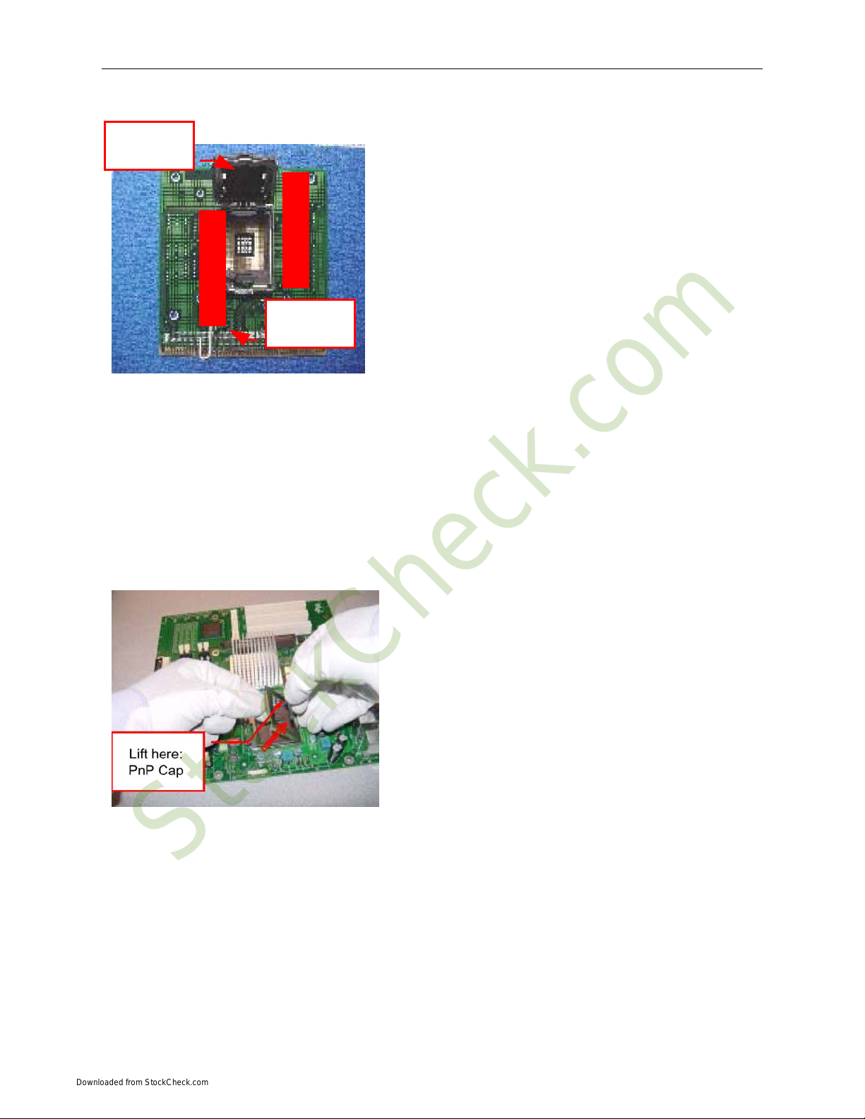
Socket Load
Plate Open.
Socket Load
Lever Open
i. Disengage Load Lever by depressing down and out on
the hook to clear retention tab
ii. Rotate Load Lever to fully open position at
approximately 135degrees
iii. Rotate Load Plate to fully open position at
approximately 100degrees
2. Remove PnP Cap (Pick & Place Cap)
i. With left hand index finger and thumb to support the load plate edge, engage PnP cap with right hand
thumb and peel the cap from LGA775 Socket while pressing on center of PnP cap to assist in removal.
ii. Set PnP cap aside. Always put PnP cap back on if the processor is removed from the socket.
iii. Visually inspect PnP cap for damage. If damage observed, replace the PnP cap.
Note: After PnP cap removal, make sure socket load plate and
contacts are free of foreign material; Refer to Overview
Module for FM cleaning.
Note: Optionally, remove PnP cap after CPU insertion. This
will compromise the ability to visually inspect socket.
3. Visually inspect for bent contacts (Recommended at least 1st pass visual inspection)
NOTE: Refer to the Handling and Inspection Module for 1st and 2nd pass inspection details.
NOTE: Glove manipulation images are for illustrative purposes only. Please consult local safety guidelines for
specific requirements.
NOTE: Recommended not to hold the load plate as a lever, instead hold at tab with left hand, removing the PnP cap
with right hand.
7
StockCheck.com
Downloaded from StockCheck.com
Phoenix MicroATX Express – Installation Guide
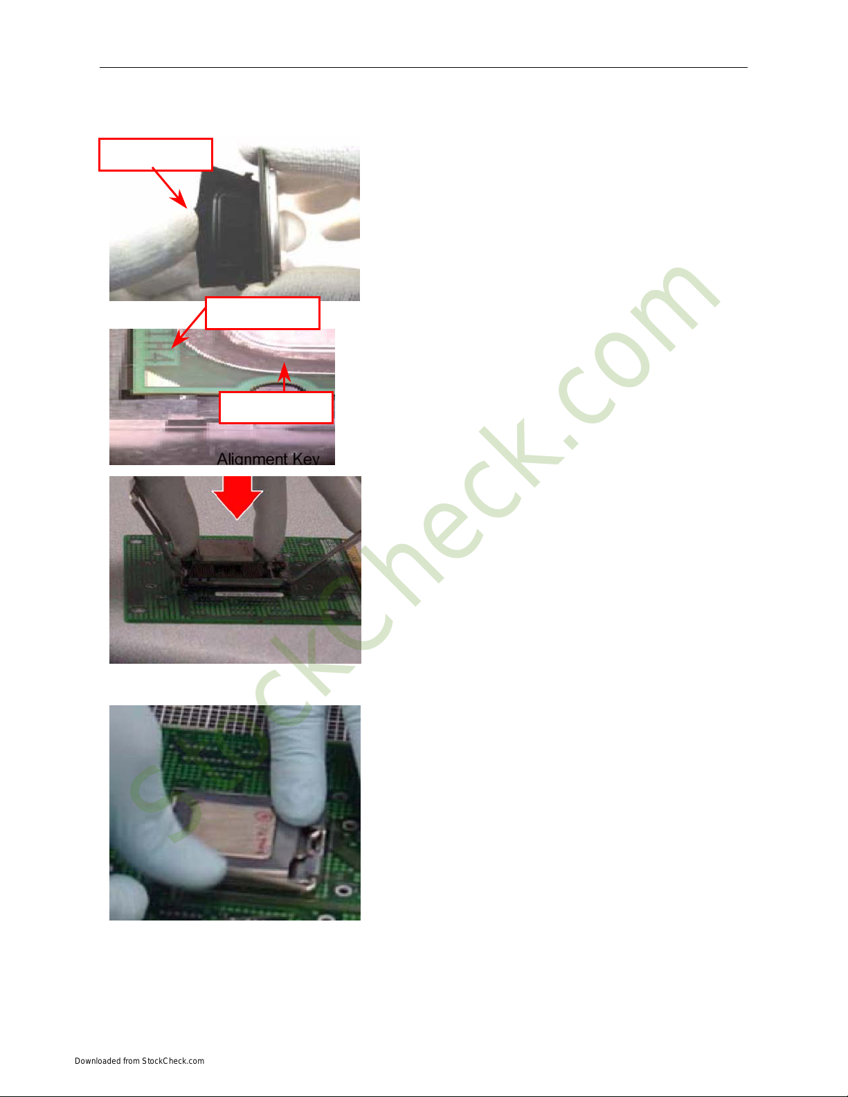
775- Land LGA Package Insertion
A
lignment Ke
y
Press to remove
Pin 1 Indicator
• Lift processor package from shipping media by grasping the
substrate edges ONLY.
Note:Orient processor package such that the Pin 1 triangle mark
is on bottom left and both key notches are on left side
• Land Side Cover Handling: Remove land side cover with the
opposite hand by depressing larger retention tab and peeling
the cover away
• Set and reserve the land side cover aside.
Note: Always keep the land side cover on the processor when
not in the socket.
• Visually inspect the package gold pads: Scan the processor
package gold pad array for presence of foreign material.
Refer to Overview Module for FM cleaning
recommendations
• Orient the package with IHS up. Locate Pin 1 and the two
orientation key notches
• Carefully place the package into the socket body using a
purely vertical motion
CAUTION: Using Vacuum Pen for installation is not
recommended
• Verify that package is within the socket body and properly
mated to the orient keys
• Close the socket by:
1. Rotating the Load Plate onto the package HIS
2. While pressing down lightly on Load Plate, engage the
Load Lever.
3. Securing Load Lever with Load Plate tab under
retention tab of Load Lever
8
StockCheck.com
Downloaded from StockCheck.com

Chapter 1: Pre-Configuration
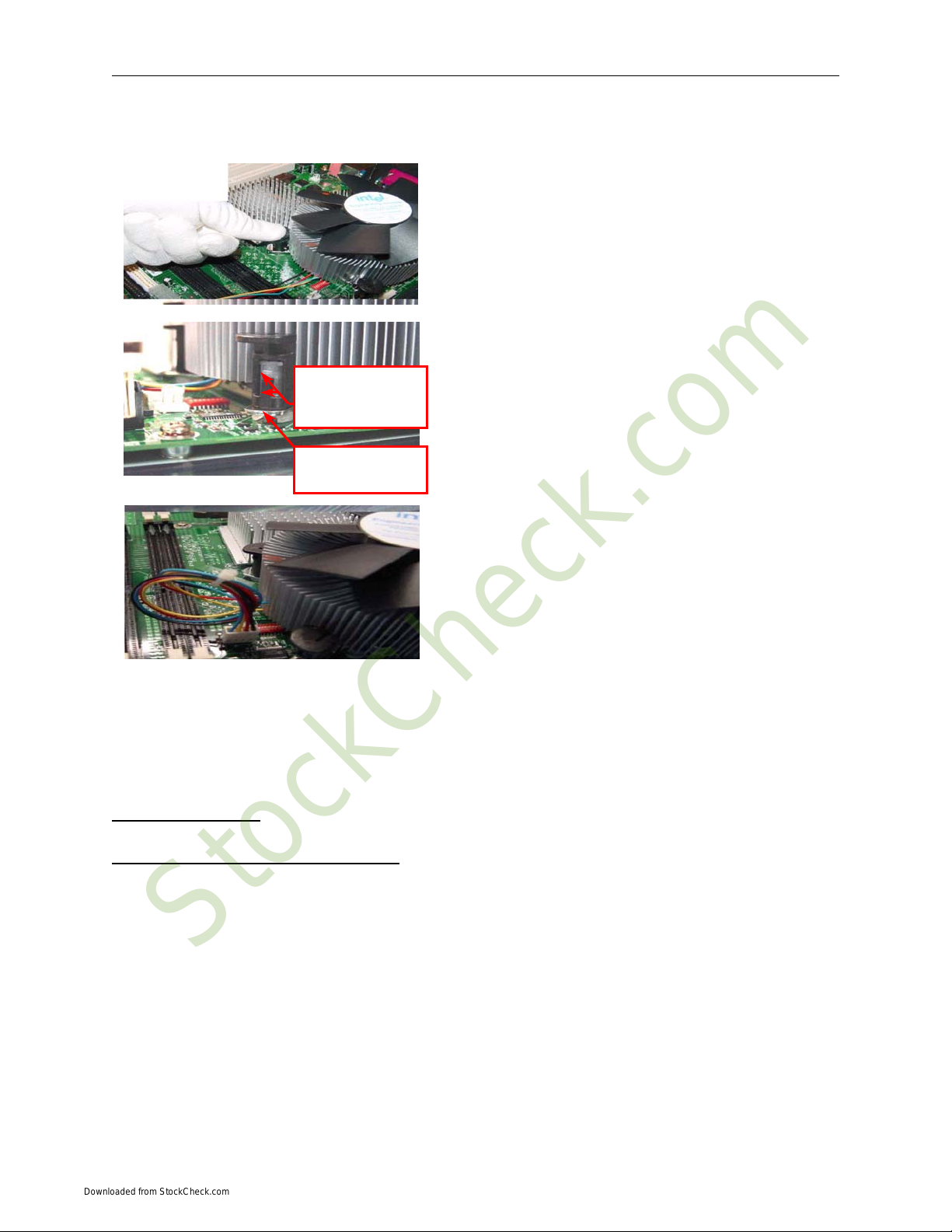
Intel Reference Thermal Solution Assembly
NOTE: Depending on the configuration, Thermal Solution Integration procedure could perform with M/B alone or
with M/B in the Chassis.
1.
2.
3.
4.
5.
Place motherboard on support structure providing
minimum 0.150-inch backside clearance
Apply 300 mg of Thermal Interface Material onto center
of IHS
NOTE: Thermal Solutions that come with IntelR boxed
processor use pre-applied thermal interface material and not
grease.
Remove Heat Sink (HS) from packaging media
Place HS onto the LGA775 Socket
• Ensure fan cables are oriented on side closest to fan
header
• Align Fasteners with MB through-holes
0.150-inch backside
clearance for fastener
installation
Fan cabled on side
closest to MB heade
r
Fastener slots
pointing straight out
A
pply Thermal
Interface Material
Inspection
• Ensure cables are not trapped or interfere fastener
operation
• Ensure fastener slots are pointing straight out from
heatsink
9
Fastener flush
against MB
Fastener Cap not
resting against spring
StockCheck.com
Downloaded from StockCheck.com
Phoenix MicroATX Express – Installation Guide
6.
7.
8.
9.
Actuate fasteners
Both fastener
halves are flush
against spring
Fastener flush
against spring
• While holding HS to prevent tilting, press down on
fastener caps with thumb to install and lock
Repeat with remaining fasteners
Inspection
• Verify the fasteners are properly seated
• Ensure both fastener cap and base are flush with spring
and motherboard
Connect fan header with Board header
Secure excess cable with tie-wrap to ensure cable does not
interfere with fan operation or contact other components.
This completes the installation of the CPU. Now is it a good time to double check both the CPU and the DIMM
installation to make sure that these devices have been properly installed.
Installing Cables
Power and Control Panel Cables
The Phoenix MicroATX Express gets power from the ATX connector J32 (Figure 1-2) and ATX 12V J24 (Figure
1-2).
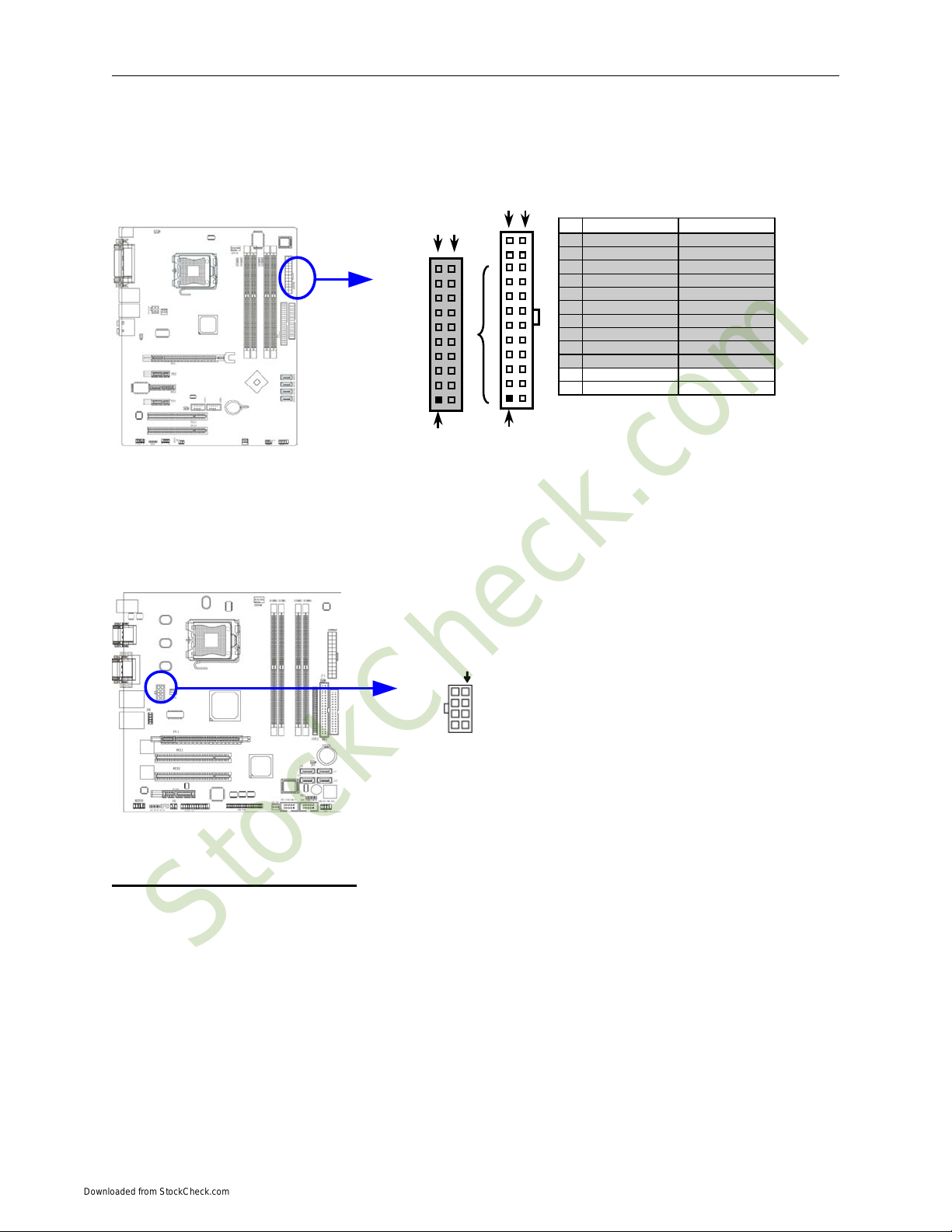
Power Connector (24-pin block): ATXPWR24P(J32)
ATX Power Supply connector. This is a newly defined 24-pin connector that usually comes with an ATX
case. The ATX Power Supply allows using soft power on momentary switch that connect from the front panel
switch to 2-pins Power On jumper pole on the motherboard. When the power switch on the back of the ATX power
supply is turned on, the full power will not come into the system board until the front panel switch is momentarily
pressed. Press this switch again will turn off the power to the system board.
** We recommend that you use an ATX 12V Specification 2.0-compliant power supply unit (PSU) with a
minimum of 350W power rating. This type has 24-pin and 4-pin power plugs.
10
StockCheck.com
Downloaded from StockCheck.com
Chapter 1: Pre-Configuration
** If you intend to use a PSU with 20-pin and 4-pin power plugs, make sure that the 20-pin power plug can
provide at least 15A on +12V and the power supply unit has a minimum power rating of 350W. The system may
become unstable or may not boot up if the power is inadequate.
Pin 1
PIN ROW1 ROW2
1 3.3V 3.3V
2 3.3V -12V
3 GND GND
4 5V Soft Power On
5 GND GND
6 5V GND
7 GND GND
8 Power OK -5V
9 +5V (for Soft Logic) +5V
10 +12V +5V
11 +12V +5V
12 +3V GND
Pin 1
ROW2ROW1
ROW2ROW1
24-Pin
20-Pin
ATX 12V Power Connector (8-pin block): ATX12V(J24)
This is a newly defined 8-pins connector that usually comes with an ATX Power Supply. The ATX Power
Supply, which fully supports Pentium D processors, must include this connector to support extra 12V voltage to the
system. DO NOT USE 2x3 plugs.
Pin 1
Installing Peripheral Cables
Now it is a good time to install the internal peripherals such as floppy and hard disk drives. Do not connect the
power cable to these peripherals, as it is easier to attach the bulky ribbon cables before the smaller power
connectors. If you are installing more than one IDE drive double check your master/slave jumpers on the drives.
Review the information supplied with your drive for more information on this subject.
Most modern HDDs are UDMA-5 capable. To make use of the Ultra DMA-5 capabilities, 80-conductor cables must
be used. The BIOS and the HDD will check for the existence of the 80-conductor cable. The long leg of the cable
must be connected to the board; otherwise it won’t work as an 80-conductor cable. If connecting another peripheral
that is not UDMA-5 capable (most optical devices are not), the whole IDE channel will be downgraded to UDMA-2.
In that case, it is recommended to use a different IDE channel for the non-UDMA-5 capable peripherals.
11
StockCheck.com
Downloaded from StockCheck.com

Phoenix MicroATX Express – Installation Guide
Connect the floppy cable (not included) to the system board. Finally, connect the IDE (Parallel and Serial ATA)
cables (not included) to the system. If using a Solid State Device, connect it to the mini-ATA connector. Connect all
interface cables to their headers. Then connect remaining ends of the ribbon cable to the appropriate peripherals.
This concludes the hardware installation of your Phoenix MicroATX Express system. Now it is a good time to re-
check all of the cable connections to make sure they are correct.
12
StockCheck.com
Downloaded from StockCheck.com
Table of contents


