Powr-Kraft AT Series Application guide

1 Revision1-3-2018
1
Specificationssubjecttochangewithoutnotice.
www.Betstco.com
Phone: 541-895-3083
E-mail [email protected]
83371 Melton Rd, Creswell OR 97426
Rugged Labor Saving Equipment Since 1995
FOR YOUR SAFETY!
Please read these instructions carefully before using! Retain this
manual for future operators to read. Check all fluid levels before each
use! GREASE ALL FITTINGS BEFORE OPERATING!
OPERATION & PARTS MANUAL
Pull Behind Power Flail Mower AT Series

2 Revision1-3-2018
2
Specificationssubjecttochangewithoutnotice.
INDEX
Section: Description: Page
No:
1 Introduction 3
HSE information sheet 4
2 In the interest of safety: DO NOT 6
3 In the interest of safety: DO 6
4 Instruction & Warning Decals 7
5 Operating Instructions And Adjustments 8
5.1 Initial Check 8
5.2 Drawbar Adjustment 9
5.3 Mower Cutting Height 10
5.4 Starting The Engine 10
5.5 Forward Speed 11
5.6 Stopping The Mower 11
5.7 Transport Position 11
5.8 Anti-scalping roller / Side skid′s 12
6 Maintenance Schedule 13
6.1 Engine 13
6.2 Excess Crop Build Up 13
6.3 Visual Check 13
6.4 tire Pressures 14
6.5 Rotor Bearing Inspection 14
6.6 Wheel Bearing Inspection 14
6.7 Oil Coupling / Bush Wear 14
6.8 General Inspection 14
6.9 Rotor Flail Maintenance 14
7 Parts List 16
8 Warranty 28

3 Revision1-3-2018
3
Specificationssubjecttochangewithoutnotice.
With the purchase of your FLAIL MOWER you have made an excellent choice.
This machine should give first class service for a long time, if used correctly, and maintained
as described in this manual.
Fitted with an easy to start engine it has been designed to cope with a wide range of
conditions. The AT Pull behind Flail mower incorporates easy height adjustment, range of
engine options and a full width anti-scalping roller to avoid damage to machine and sward.
The mower is constructed from 4 mm steel for added strength; all fittings are of high quality to
ensure years of trouble free use.
1 INTRODUCTION

4 Revision1-3-2018
4
Specificationssubjecttochangewithoutnotice.
Selecting and using equipment for All Terrain
Vehicles (ATV's)
Introduction
This information sheet gives advice to users on how to use all Terrain vehicles (ATV's)
safely with towed and mounted equipment.
Plan the use of an ATV carefully and take particular note of ground conditions and slopes, as
these may vary considerably, depending on the terrain, weather conditions, ground surface
and the crop under the wheels.
Towed Equipment
Choose equipment which matches your ATV. Stability of towed equipment is affected by:
Weight Ratios
1. The safe ratio between the trailed loaded maximum weight and unloaded weight of the
ATV must be assessed for each operation.
2. Always take note of information given in the manufacture′s handbook when making this
assessment.
3. As a guide research shows that on level ground, 4 x unloaded weight of the ATV for braked
trailed equipment and 2 x unloaded weight of the ATV for un-braked trailed equipment are the
appropriate maximum ratios.
Note: For work on slopes or uneven ground the ratio will need to be reduced.
Braking
Fit:
1. Brakes to trailed equipment. This helps prevent jack-knifing when braking or traveling
downhill;
2. Over-run brakes which come into action whenever the ATV brakes are applied;
3. A manually operated parking brake operable from the driving position. This provides control
for use when going up slopes.
Hitching and Loads
Stability is also improved if:
1. Some weight is transferred from the trailer onto the ATV draw-bar;
2. The draw-bar has a swivel hitch and the ATV a ball hitch having a large head to neck ratio.
This makes it easier for the draw-bar hitch to swivel and cope with undulating ground;
3. The load is positioned as near to the center of the trailer as possible.
Tires and Wheels
1. Check tire pressures regularly with a pressure gauge capable of reading low pressures
accurately;
2. Check tires regularly for damage and wear;
3. Select equipment which has tires and wheels that can cop with speeds over 20 mph and
occasional higher speeds;
4. Use wheels with bead locks on the rims if the main use is going to be on sloping ground.
This prevents tire run-off on side slopes.

5 Revision1-3-2018
5
Specificationssubjecttochangewithoutnotice.
Maximum Towed Weight
Follow the advice given by manufacturers on the maximum trailed weight. This will be found
on the equipment or in the instruction handbook.
Note: Universal road going trailers will normally have the maximum gross weight stated on a
separate notice.
Mounted Equipment
ATV's using mounted equipment are safer if the equipment has:
·a low center of gravity. This improves stability.
·a gross weight within the limits approved by ATV manufacturer.
·no dangerous projections to injure the operator or bystanders;
·no forward projections which stop head protection being worn;
·controls which are easy to work and which do not create a hazard to the operator;
Instructions for Mounted and Trailed Equipment
Take note of the manufacturer′s instructions on:
·operating on slopes;
·where to place loads so as to give fore/aft and lateral stability;
·the risks of using equipment with negative drawbar nose weight, ie loss of traction;
·the maximum operating speed;
·the effect that equipment carried on front and/or rear racks will have on longitudinal and
lateral stability;
·securing loads;
·the use of ballast, if any, to improve stability;
·the need to select and use safe routes.
Using an ATV
·Read the manufacturers′s instruction book and take note of the safety advice given;
·Choose an ATV with enough power for the work you want it to do. four-wheel driver will give
better traction and mobility and may provide a margin of safety;
·Choose a safe route;
·Be aware that increased speed greatly increases the risk of instability and risk of and
overturn;
Training
Train everyone who has to use an ATV whether with mounted or trailed equipment or as a
solo machine. The training should emphasize the factors affecting stability, the need for care
and concentration, and how to recognize the conditions which may affect the safety of
operation, It is important for trainees to familiarize themselves with the handing and control of
the machine on level open ground before tackling rough hill terrain.
Suitable training courses are run by bodies such as ATV Landbase and the forestry Authority.
Helmets
Wear head protection which protects the head and neck. Helmets are suitable. Some users
find open faced helmets more suitable than full face helmets.
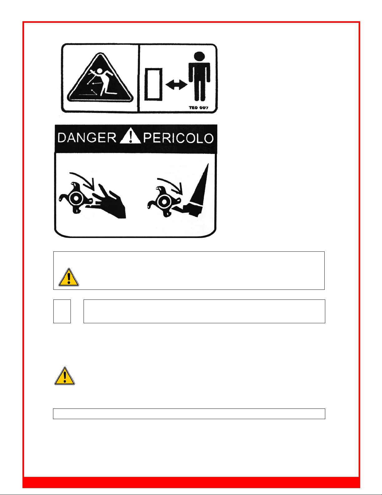
This symbol means WARNING or CAUTION Personal safety or damage will be at
risk if these instructions are ignored. Most accidents are caused by neglect of
carelessness; Avoid needless accidents by following the safety precautions listed
below.

6 Revision1-3-2018
6
Specificationssubjecttochangewithoutnotice.
2IN THE INTEREST OF SAFETY:DO NOT
1. DO NOT- Operate the mower without all the correct guards fitted.
2. DO NOT- Alter engine settings unless stated by Engine manufacturer.
3. DO NOT- Touch any moving or rotating parts, during working conditions
4. DO NOT- Stop the engine immediately after heavy use, (See section 5.6)
5. DO NOT- Operate the mower without suitable ear and eye protection
6. DO NOT- Allow passengers.
7. DO NOT- Leave machine unattended while operating
8. DO NOT- Run the engine in an enclosed area, exhaust gases contain Carbon Monoxide
and are fatal if inhaled.
9. DO NOT- Operate the mower on excessively steep slopes.
10. DO NOT- Operate the mower unless all safety features are fitted to the mower and are
used correctly
11. DO NOT- Operate the mower until you have read and understood the entire operators
manual
12. DO NOT- Wear loose fitting clothing, to avoid catching on parts of the machine
13. DO NOT- Try to remove blockages while the engine is running. Ensure engine is
stopped and the rotor has finished rotating, before any servicing takes place to your
mover.
14. DO NOT- Operate the mower in dark conditions unless suitable artificial light is used.
15. DO NOT- Operate if excessive vibration occurs, stop the machine immediately and view
maintenance chart.
16. DO NOT- Climb on the mower.
3 IN THE INTEREST OF SAFETY:DO
1. DO- Follow engine manufactures guideline.
2. DO- Ensure all spectators are a safe distance away when operating.
3. DO- Carry out regular servicing and checks before use.
4. DO- Clear cutting area from potential damaging components.
5. DO- Reduce speeds when working on hillsides or rough terrain
6. DO- Be aware components can be hot after operation
7. DO- Follow any towing guidelines stated by ATV manufacturer.
8. DO - Show some caution when filling the tank with fuel, especially if engine
components are hot.
9. DO- Ensure all safety decals are in good condition, replace any that are damaged.
10. DO- Keep hands and feet away from rotating blades
11. DO – Ensure mower is in transport position before transporting from workplace.

7 Revision1-3-2018
7
Specificationssubjecttochangewithoutnotice.
4 INSTRUCTION / WARNING DECALS
KEEP WHEEL NUTS TIGHT
CHECK DAILY
REFER TO THE OPERATORS MANUAL
FOR CORRECT tire INFLATION PRESSURE
OBSERVE TOWING VEHICLE MAX TOWING LIMITS OR TRAILER MAX WEIGHTS
ATTENTION
Your responsibilities before operating this machine are:
· Read understand and follow the safety procedures manual
· Train operators before using & review safety procedures regularly
· Ensure that all guards are in place before operating
· Keep hands, feet, hair and clothing away from all moving parts
· Avoid wearing loose clothing whenever possible
· Maintain as per schedule in the safety procedures. Especially blades and securing hardware,
due to hazard they present should any part break loose during operation
· During maintenance, use suitable support stands
· DO NOT allow any persons to ride on the equipment

8 Revision1-3-2018
8
Specificationssubjecttochangewithoutnotice.
The above decals should be located on your AT – Flail Mower. If any of the above
decals are not located on your AT or are damaged in damaged in any way contact
for some replacement decals before use.
5 OPERATING INSTRUCTIONS AND
ADJUSTMENTS
The AT FLAIL MOWER is designed to give safe and dependable service if operated
according to instructions and intended use.
Read and understand this manual before operating the mower, as failure to do so could result
in personal injury or equipment damage.
When used with and ATV or compact tractor, ear defenders should be worn. Under
normal working conditions a noise level of 83 decibels would be usual, in the case protection
is advised.
5.1 INITIAL CHECK
1. Make sure that all nuts, bolts and fittings are securely fixed, and that all packaging
materials e.g. wire bands, tape etc have been removed. (Remove tape from the front
stone deflectors from the underside of the body)
2. Check the there is oil in the engine and petrol in the tank.
3. Check tire pressures.

9 Revision1-3-2018
9
Specificationssubjecttochangewithoutnotice.
5.2 DRAWBAR ADJUSTMENT
The drawbar attachment height of the towing vehicle can vary. To accommodate adjustment,
a screw link is located beneath the drawbar. This should be lengthened or shortened so that
the cutting deck is horizontal to level ground. (This ensures a better cutting efficiency)
TO ADJUST
1. Unlock the locking nut (A)
2. Lengthen the link to lower the front of the deck or shorten to raise the deck.
3. Once the deck is level, re-tighten locking nut (A).
QUICK OFFSET DRAWBAR
Unlock the nut and screw slide the drawbar to the desired position and release the screw into
the securing hole then lock the nut, as shown.
A
hole settings

10 Revision1-3-2018
10
Specificationssubjecttochangewithoutnotice.
The main cutting height adjustment is achieved by using the screw jack, to raise or lower the
cutting deck as necessary.
CUTTING HEIGHT ADJUSTMENT:
Turn the handle to raise or lower as necessary.
5.4 STARTING THE ENGINE
READ AND UNDERSTAND THE ENGINE OPERATORS MANUAL
BEFORE USE
Observe all safety precautions; keep hands and feet away from rotor and other
moving parts. Keep spectators at a safe distance.
1. Make sure there is a gap between the blades and the ground / crop
2. Select an area clear of loose debris that could be picked up.
3. Set the engine choke, and suitable idling speed with the throttle.
4. Place one foot on top of the deck body to give a firm and balanced position. Pull the
starter cord firmly, allowing the cord to return to return to the housing slowly (one or two
strong pulls should start the engine).
5. After a few seconds warming up at idling speed, move the throttle to the factory pre-set
working position to give a normal/working engine R.P.M of 3600 max.
NOTE
If the throttle is altered to increase the engine R.P.M beyond the recommended level, the
guarantee may become invalid. In addition to this, cutting efficiency will be reduced, fuel
consumption will increase and excessive vibration could be caused, resulting in a potential
danger to personnel and damage to components.
ELECTRIC START
Push button electric start engine options can be supplied if required. Simply hitch up the
mower, connect the electrical supply plug to the ATV socket and turn the ignition key to start
the mover. Observing all the precautions mentioned above in ‘Starting the mower’.
REMOTE THROTTLE CONTROL
When a remote throttle control option is fitted, normally to the rear carrier frame of an ATV or
other suitable site on the towing vehicle, it gives the operator the facility of controlling the
5.3 MOWER CUTTING HEIGHT

11 Revision1-3-2018
11
Specificationssubjecttochangewithoutnotice.
mower engine from the operating position.
The facility is most beneficial when moving from one cutting site to another close to it, by
reducing the engine revs to allow the mower flails to come to rest, no harm will be caused to
the mower or ground surface during transport, often over rough or difficult terrain when
stones and loose objects may be encountered.
5.5 FORWARD SPEED
The amount of grass or weeds to be cut dictates the forward speed; slow forward speeds give
better results in most cases. Ensure you follow the procedure below.
NORMAL FORWARD SPEED (1 kph- very heavy use- 10 kph - very light use)
Start off in the slowest speed possible, ensure the mower is working efficiently with the engine
set at maximum RPM and not laboring. (If this is not possible due to very heavy cutting
conditions, raise cutting height of blades and be prepared to go over twice with machine set
lower on 2nd pass, leave at least 24 hours in between 1st and 2nd cut to allow grass to dry
out)
Increase forward speed until the RPM of the engine starts to slow down (This is working the
engine too hard for conditions) – slow down, let the engine regain full RPM and go through
the same process but stop short of speed which made engine labor previously. It is
important always to listen to note of engine to ensure engine and mower are working
efficiently, slow down or stop once engine starts to labor.
FAILURE TO DO THIS WILL RESULT IN CLUTCH SLIP AND
ULTIMATELY SEVERE DAMAGE TO THE CLUTCH AND DRIVE
BELTS.
5.6 STOPPING THE MOWER
When stopping the mower after a period of heavy use. Run the machine at half working
speed in a stationary position, for at least 4 minutes, to allow the drive belts to cool down.
1. Show caution to hot parts e.g. engine exhaust, belts etc after engine is switched off.
2. Ensure the mower drawbar has been adjusted to allow the mower to run directly behind
the towing vehicle and is not in an offset position
3. When the mower has cooled down (Min 1 hr after last used) Ensure all grass has been
removed from engine cooling fins, drive belt area, and rotors before operating again.
5.7 TRANSPORT POSITION
When the mower is being moved from one site to another it is advisable to raise the deck to
the highest position (Transport position, See section 5.3 “Mower cutting height”)
The engine must be stopped and the blades at a standstill before adjusting to the transport
position.
Remove any crop debris from the deck before leaving the field.
Never move from one site to another with the engine running.
Please note the AT – Flail Mower is not road legal, and should not be used on public
roadways
When moving from normal working conditions to heavier cutting, it may be
evident that the engine dies down and loses revs. SLOW DOWN IMMEDIATELY to allow the
engine revs to build up again to normal working speed. Follow the procedure detailed above
in “Normal Forward Speed”. Expected forward speed will be much lower in heavy conditions.
FAILURE TO DO THIS WILL RESULT IN CLUTCH SLIP AND
ULTIMATELY
SEVERE DAMAGE TO THE CLUTCH AND DRIVE BELTS.

12 Revision1-3-2018
12
Specificationssubjecttochangewithoutnotice.
5.8 ANTI-SCALPING ROLLER/SIDE SKIDS
The main purpose of the anti scalping roller is to prevent damage .If a wheel drops into a hole,
or there is uneven ground between the wheels, the roller takes the weight of the mower,
avoiding the flails scalping the ground;combined with the side skids the mower provides good
protection to the rotor.
The anti scalping roller has the added advantage of-enabling curb side grass to be cut with no
difficulty, by allowing the wheel to hang over the curb edge.
The factor pre-set position of the anti scalping roller and side skids are suitable for most
situations.
However, if the mover is used in rough conditions or regularly in heavy crops, the roller and
side skids should be lowered, to increase the clearance between the flail and the ground
when the roller comes into use.
In circumstances where the mower is being used as a “Finishing Mower” and a striped
appearance is desired, the roller can be set down using the various hole positions to give the
required cutting height, then the wheels can be lifted clear of the ground.
TO ADJUST THE
ROLLER:
Slacken pivot bolt “A”.
Slacken and remove bolt
“B”(Repeat for both ends of the roller)
Select another hole and
Replace bolt “B”. Tighten bolts “A” and “B”
TO ADJUST THE SIDE SKIDS:
Remove the bolt at the
Front of the skid and the rear of the skid (show as “C”) Select new setting, replace the bolts
and tighten. Repeat for the opposite skid; always ensure both skids are set to
A
B

13 Revision1-3-2018
13
Specificationssubjecttochangewithoutnotice.
6 MAINTENANCE
Maintenance Schedule
Maintenance Operation: Hourly Daily Weekly Seasonal
Engine (See Engine manufacturers manual) ● ● ● ●
Remove excess crop gathered on deck ● ● ● ●
Remove excess crop wrapped around rotor
ends ● ● ● ●
Visual check to ensure nothings loose ● ● ●
Grease Height Adjuster ● ● ●
Grease Rear Roller ● ● ●
Grease Rotor Bearings ● ● ●
tire Pressures ● ●
Drive belt inspection ● ●
Rotor Bearing inspection ● ●
Wheel bearing inspection ● ●
Oil 50 mm coupling ● ●
Swivel hitch Bush Wear ● ●
Check All Fasteners are tight and intact ● ●
Safety Chain Guard inspection ● ●
Safety Decals intact ● ●
Safety Guards Intact ● ●
Check Blade wear / condition ●
Check Metal Fatigue ●
Clutch Wear / Function ●
6.1 ENGINE
Refer to engine manufacturers manual, for servicing and maintenance of the engine.
6.2 EXCESS CROP BUILD UP
Remove all crop deposits from the deck, and engine area. Build up of crop deposits could
result in heat build and fires
Disconnect the spark plug lead.
Remove any crop that is wrapped around the end of the rotor (A) or on the underside of the
deck. Raise the deck to its max height to assist access to the rotor shaft.
A

14 Revision1-3-2018
14
Specificationssubjecttochangewithoutnotice.
6.3 VISUAL CHECK
Make a visual check around the mower, check for missing / loose parts or damaged / worn
components. All-faults must be either repaired or replaced.
6.4 TIRE PRESSURES
DO NOT exceed recommended type pressures
22×1100 -8 7 – 10 PSI
16.5×6.50 -8 28 PSI (Max)
6.5 ROTOR BEARING INSPECTION
Rotate rotor shaft by hand and feel for any roughness in the bearings. Also try to pull the shaft
from side to side to see if any movement is found. If symptoms persist strip down the
rotor-housing unit and inspect bearings.
6.6 WHEEL BEARING INSPECTION
Jack one side of the mower body up, so the wheel is just off the ground. Rotate the wheel by
hand, and check the wheel alignment. To check the bearing, try to move the wheel from left to
right and feel for any play in the bearings (A), ensure the wheel-locating bolt is tight before
you start and follow any jacking procedures. If any play is found remove the wheel and
inspect bearings. Replace any faulty bearings.
6.7 OIL 50 mm COUPLING/BUSH WEAR
Check coupling for signs of damage or wear, swivel the coupling 36. degrees and check that
the bushes are not too worn. Replace any worn or damaged parts.
Oil the coupling regularly as shown below.
6.8 GENERAL INSPECTION
Check the mower to ensure all fasteners are tight and all safety guards / chains are intact and
fitted securely. Check all safety-warning decals, Replace any defective guards or damaged
decals.

15 Revision1-3-2018
15
Specificationssubjecttochangewithoutnotice.
6.9 ROTOR FLAIL MAINTENANCE
The AT range has “Rock” knives designed to last a long time. The standard knives are
double edged for even longer life. However, when breaking or losing a knife, it is important to
replace it immediately. Failure to do this can cause serious unbalancing problems. (Always
use spare parts)
At the time of replacement, the opposite knife on the rotor should be checked for wear. If it is
partially or well worn then if should be changed to maintain an accurate weight balance.
When the first cutting edge is becoming blunt, the whole set of flails should be turned around.
(Using blunt knives will reduce the cutting efficiency and increase fuel consumption).
Replacing or reversing the knives follows this simple procedure:
(A) Ensure mower engine has stopped and the knives have stopped rotating. Switch of
the fuel tap and let the machine cool down for 5 minutes. Remove the spark plug to
ensure the engine cannot be started.
(B) Raise the mower to its max cutting height.
(C) Carefully raise the drawbar to an incline position, so that height adjuster bar at the
rear of the mower takes the weight. NB; Do not attempt this with the wheels behind
version; raise the front jack to its max height.
(D) Slacken and take out the shackle bolt.
(E) Replace or turn around blades (Note the direction of rotation)
(F) Replace shackle bolt securely, but still allowing the shackle to swing on the fixing
bush.
NOTE:
Never use cracked or repaired shackles when replacing knives. If the shackle fixing has
become damaged or worn, replace with new parts
For repairs beyond the minor adjustments listed above, contact your local dealer
or contact.

16 Revision1-3-2018
16
Specificationssubjecttochangewithoutnotice.
Your PK-AT Flail accepts only EF and EFG series

17 Revision1-3-2018
17
Specificationssubjecttochangewithoutnotice.

18 Revision1-3-2018
18
Specificationssubjecttochangewithoutnotice.
ATV Flacil Mower Assembly
NO. Part NO. Name &Specifications Quantity Remark
1 GB5783-86 M12x30 Blot M12x30 19
2 GB93-87 12 Spring washer 12 9
3 GB97.1-85 12 Plain waher 12 37
4 MFP120.00.106 Fixing sleeve 1
5 GB894.1-85 35 Circlip 35 1
6 GB893.1-86 62 Circlip 62 2
7 GB278-89 6007Z Bearing 6007Z 2
8 MFP120.00.152 Driving Belt wheel 1
9 MFP120.00.017 Clutch 1
10 GB1096-79 6.3x7x50 Key 6.3x7x50 1
11 MFP120.00.018 Protecting for transmission 1
12 GB6184-86 M12 Locking nut M12 42
13 GB5783-86 M12x35 Blot M12x35 4
14 GB5783-86 M8x20 Blot M8x20 8
15 GB93-87 8 Spring washer 8 8
16 MFP120.00.155 Supproting plate (R) 1
17 EF100.00.012 UC205
Bearing UC205
2
18 RK120.017 Roller weldment 1
19 JF390 Gasoline engine 1
20 MFP120.00.156 Supporting plate (L) 1
21 MFP120.00.012 Deck weldment 1
22 GB91-86 4X28 Split pin 4x28 1
23 MFP120.00.026 Adjusting plate (R) 1
24 MFP120.00.025 Adjusting plate (L) 1
25 RK120.020 Blade axle 1
17

19 Revision1-3-2018
19
Specificationssubjecttochangewithoutnotice.

20 Revision1-3-2018
20
Specificationssubjecttochangewithoutnotice.
ATV Flacil Mower Assembly
NO. Part NO. Name &Specifications Quantity Remark
26 EF100.00.101 Sleeve 56
27 RK120.114a Blade 28
28 GB5782-86 M12x80 Blot M12x80 28
29 EF100.00.122 Baffle 12
30 EF100.00.121 Baffle 1
31 MFP120.00.109 Shaft 1
32 MFP120.00.024 Protecting bracket 2
33 MFP120.00.116 Tension spring 1
34 UC207-Z 90207 Bearing seat 90207 2
35 GB13871-94 FB55X80X8 Oil seal FB55x80x8 2
36 RK120.109 Oil-sealing sleeve 2
37 GB1152-89 M8X1 Oil cup M8x1 1
38 MFP120.00.036 Bracket for tension spring 1
39 GB97.1-85 10 Plain washer 10 1
40 GB6184-86 M10 Locking nut M10 1
41 GB5783-86 M8X16 Blot M8x16 1
42 GB96-85 8 Plain washer 8 1
43 MFP120.00.153 Tensioner 1
44 GB279-88 180105 Bearing 180105 2
45 MFP120.00.154 Sleeve 1
46 GB893.1-86 47 Circlip 47 1
47 MFP120.00.101 Cover 2
48 GB5783-86 M8x25 Blot M8x25 2
49 GB97.1-85 8 Plain washer 8 2
50 GB6184-86 M20 Locking nut M20 2
19
Table of contents