Renfert Magma 2300-0000 User manual

Page 2 / 28
Contents
Contents.................................................................................................................................2
1Safety information............................................................................................................3
1.1 Information symbols in the repair guidelines..............................................................3
1.2 Qualification and training...........................................................................................4
1.3Repair works safety instruction..................................................................................4
1.4 Modifications without approval from the manufacturer...............................................5
1.5 Disclaimer ............................................................................................................5
2Contact and Service address...........................................................................................6
3Needed tools and utilities.................................................................................................6
3.1 Test equipment.....................................................................................................6
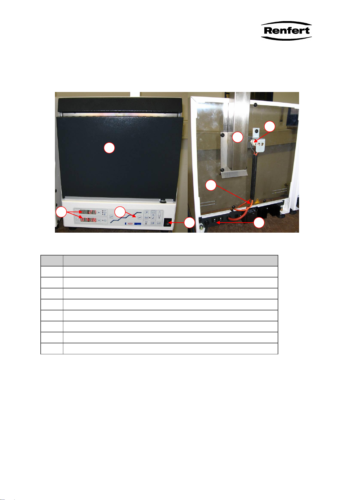
4General Overview............................................................................................................7
4.1 Description / Application area....................................................................................8
4.2 Technical Data..........................................................................................................8
5Repair Works...................................................................................................................9
5.1 Door removal/mounting, Change of door firebrick......................................................9
5.1.1 Replacing of the handle ........................................................................................9
5.1.2 Door removing ......................................................................................................9
5.1.3 Replace door firebrick.........................................................................................10
5.1.4 Door sensor replacement....................................................................................11
5.1.5 Door mounting. ...................................................................................................11
5.2 Rim stone replacement............................................................................................12
5.2.1 Remove the ledge...............................................................................................12
5.2.2 Removing front panel and replacement of rim stone ...........................................12
5.2.3 Install front panel and ledge................................................................................13
5.3 Control unit and backup battery...............................................................................14
5.3.1 Operating unit board ...........................................................................................14
5.3.2 Replace the processor circuit board....................................................................14
5.3.3 Backup battery replacement................................................................................15
5.3.4 Installing control unit ...........................................................................................15
5.4 Thermocouple replacement.....................................................................................16
5.5 Replacing power electronics....................................................................................16
5.6 Compensating wire replacement.............................................................................18
5.7 Remove the heating cable.......................................................................................18
5.8 Ribbon cable replacement.......................................................................................19
5.9 ON/OFF switch replacement ...................................................................................20
5.10 Power cord replacement..........................................................................................20
5.11 Unit feet replacement ..............................................................................................21
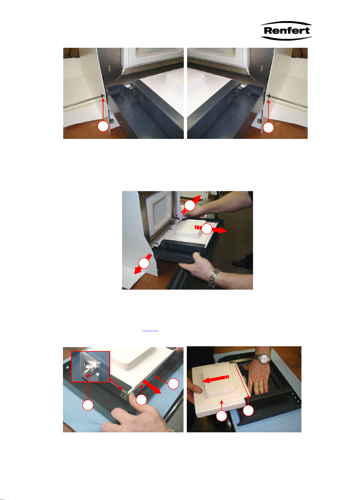
5.12 Muffle replacement..................................................................................................21
5.12.1Removing the muffle ...............................................................................................21
5.12.2Installing the new muffle..........................................................................................22
6Adjustment.....................................................................................................................24
7Function check after repair.............................................................................................24
8Maintenance..................................................................................................................24
9Spare part......................................................................................................................24
9.1 Spar part drawing –Version A and B.......................................................................25
9.2 Spare part list - version A and B..............................................................................26
10 Troubleshooting.............................................................................................................27
10.1 General errors.........................................................................................................27
10.2 Controller errors ......................................................................................................28

Page 3 / 28
1 Safety information
These repair guidelines include essential notices that must be observed during repair
work. It is important the service technician read these guidelines before beginning re-
pairs. Not only the general safety instructions under the main safety notices should be
observed, but also the additional specialized safety instructions.
1.1 Information symbols in the repair guidelines
Failure to obey safety instructions included in this guideline may result in personal in-
jury and are marked with danger symbols
Warning symbol: general danger
Failure to obey safety instructions may result in damage to the appliance and its
proper functioning and are identified by the following symbol.
Waning symbol: risk of electrical shock!
When you see this sign, you should always check for the appliance for being voltage
free and being protected against enabling by mistake.
The Caution! box denotes a hazard. It calls attention to a procedure, practice, or the
like, which, if not correctly performed or adhered to, could result in personal injury.
Do not proceed beyond a caution box until the indicated conditions are fully under-
stood and met.
Warning notice: Electrostatically endangered parts
Warning, hot surface
Wear dust mask
Wear gloves
Caution!

Page 4 / 28
Notices found on the appliance itself must be observed without fail.
1.2 Qualification and training
Personnel deployed on repair and maintenance work must be adequately qualified. If
personnel do not have the necessary qualifications, they must be instructed or trained
as required. Further, it must be ensured that personnel fully understand the content of
these guidelines.
1.3 Repair works safety instruction
The preheating furnace is an electrical device with inherent hazard potential. This de-
vice may only be installed and operated by authorized specialists after examination of
compliance with locally applicable standards. The following safety instruction must be
strictly observed during operation and maintenance works
Only intended for indoor use. The unit is only designed for dry applications and may
not be operated or stored outdoors or under wet conditions.
The unit may not be taken into service until any required alterations to comply with
regionally specific power plug configurations have been made. Such alterations may
only be performed by a qualified electrician.
The unit may only be operated if the information on the nameplate conforms with the
specifications of your local mains power supply.
The unit may only be plugged into an outlet which is connected to a ground wire sys-
tem.
Regularly inspect connecting lines and hoses (e.g., the power cord) for damage (e.g.,
kinks, cracks, porosity) or signs of aging. Units exhibiting damaged connecting lines,
hoses, or other defects must be taken out of service immediately.
Always unplug the unit from the wall outlet before beginning any work on the unit’s
electrical components.
Only operate the oven with the supplied ceramic pad.
The oven must be immediately taken out of service if cracks result in a risk of the
heating elements being able to be touched
Warning:
Burn hazard. The exterior of the oven as well as the oven door may be hot.
Caution
Burn hazard Only open the door with the handles.
Warning
If waxes have not completely combusted, they may burst into fl ame when the door is
opened.
Caution
Burn hazard! Use sufficiently long tongs to remove hot casting dies.

Page 5 / 28
Only wear clothing made of non-melting material (cotton).
Caution
Burn hazard! Always wear heat protection gloves when loading or unloading the ov-
en.
Caution
Opening the oven door may release an initially hazardous amount of heat. Always
wear face protection when loading or unloading the oven.
An “Err” display may indicate an overheating of the oven. Do not touch the oven. Burn
hazard!
Switch the oven off at the main power switch and allow it to cool off.
Warning
Only operate the oven in well ventilated rooms. Vapours generated during waxing
and preheating must be removed by a suitable extraction hood. Refer to the wax and
investment material manufacturers’ safety data sheets and comply with all local regu-
lations with regard to possible hazards associated with these vapours.
The oven may only be set up on a non-flammable and non-combustible surface.
Never place any flammable or explosive materials on the oven or store them in the vi-
cinity of the oven.
Never store any flammable or explosive liquids or gases in the vicinity of the oven.
Never heat liquids in the oven.
Particles of the door firebrick and the insulating material can be hazardous if inhaled!
Do not damage the door firebrick. Wear personal protective equipment such as res-
piratory protection and gloves when changing the door firebrick or the muffle.
1.4 Modifications without approval from the manufacturer
Rebuilding or changes to the appliance are only permitted with the manufacturer’s
consent. Original spares and accessories serve the appliance's safety. The use of
spares other than those provided by the manufacturer is forbidden.
1.5 Disclaimer
Renfert GmbH shall be absolved from all claims for damages or warranty if:
The product is employed for any purposes other than those cited in the operating in-
structions;
The product is altered in any way other than those alterations described in the operat-
ing instructions;
The product is repaired by other than an authorized facility or if any but original Renf-
ert parts are used;
The product continues to be employed, despite obvious safety faults or damage;
The product is subjected to mechanical impacts or is dropped.

Page 6 / 28
2 Contact and Service address
If you have any enquiries about operation or servicing, please contact us at the fol-
lowing address
Renfert GmbH
Industriegebiet
78247 Hilzingen
Phone: ++49 (07731) 8208-0
Fax: ++49 (07731) 8208-70
E-Mail: info@renfert.com
Internet: www.renfert.com
Customers in the USA, Canada and Mexico please contact
Renfert USA Inc.
3718 Illinois Avenue
St. Charles, Illinois 60174
U.S.A
Phone: ++1 630 762-1803
Toll free: 1 800 336-7422
Fax: ++1 630 762 9787
Internet: www.renfertusa.com
3 Needed tools and utilities
Set of Torx screwdriver
3.1 Test equipment
Thermometer
Ohm-meter

Page 7 / 28
4 General Overview
Fig.1 - Overview
Pos.
Description
A
ON/OFF switch
B
Operating panel
C
Display for temperature and time
D
Door
E
Thermocouple
F
Wire for Thermocouple
G
Fuses and power supply
H
Flue
A
B
C
D
F
E
G
H

Page 8 / 28
4.1 Description / Application area
The Magma preheating oven is solely intended for use in dental technology laborato-
ries as well as arts and crafts and jewellery workshops. The preheating oven is solely
intended for waxing up and preheating casting dies. Only modelling waxes and mod-
elling plastics may be employed as modelling materials. Only specialist personnel
may operate the unit as incorrect operation can result in extreme deterioration in the
quality of individual pieces and may also present extreme hazards to the operator.
4.2 Technical Data
Mains voltage
230 V / 50 Hz
Power consumption
1900 W
Device fuses:
230 V = 12 A (T)
Temperature range
Ambient temp. –1100°C (2010°F)
Heat up rate:
0°C/Min –9°C/Min (0°C/Min –17°F/Min)
Muffle size
(height x width x length):
120 x 160 x 180 mm [4,7 x 6,3 x 7,1 inch]
Dimensions incl. 1 handle and
flue (height x width x length):
500 x 430 x 440 mm
[19,69 x 16,93 x 17,32 inch]
Dimensions incl. 1handle and
catalytic converter.
(height x width x length):
610 x 430 x 550 mm
[24,02 x 16,93 x 21,65 inch]
Weight (empty):
Approx. 30 kg
WARNING!
The unit operates with 230V~, Internal parts of the unit therefore carry
potentially lethal voltages. Always remove the mains plug before carrying
out repair work

Page 9 / 28
5 Repair Works
5.1 Door removal/mounting, Change of door firebrick
5.1.1 Replacing of the handle
Using the included screw, mount the handle on the side of the oven door (Figure 1),
4mm SW Allen key. The handle can be mounted on either the left or the right side.
Installation of the handle is described in the operation manual.
5.1.2 Door removing
Switch the oven off and unplug the power cord at the wall outlet.
Allow the oven to cool off.
Completely open the door.
Unhook the springs from their holder in the door (Fig 2)
Injury hazard!
The springs are under tension. Hold them when loosening.
Push the springs sidewards out of the pivots. Mark springs in order to avoid a mix up
of the springs.
Fig.2 –spring hook out Fig. 3 - remove spring
Unscrew and remove the door’s fastening screws (Fig 4+5 a)
a

Page 10 / 28
Fig.4 –left screw Fig. 5 –right screw
Gently press the metal housing outwards (Fig. 6 a) until the door is released from its
retainer
Remove the door to the front (Fig. 6b)
Fig.6 –Remove door
5.1.3 Replace door firebrick
Remove door according to 5.1.2.
After loosen the 2 pc. M4 nuts (Fig. 7 b), remove the firebrick holder (Fig. 7 a).
Fig. 7 –Remove firebrick holder Fig. 8 - remove firebrick
Pull the firebrick out of the door housing carefully. (Fig. 8 a).
a
a
a
a
a
b
b
c
a
b

Page 11 / 28
Fig. 9 –Flat spring for firebrick
Check the flat springs (Fig. 9 a) for correct seating.
Install the new firebrick in reverse order. Take care that the cutout of the firebrick
(Fig. 8 b) is located at the upper end of the door.
Install the brick holder and fasten the 2 nuts (Fig 7a). Adjust the lugs at the side of the
side of the door housing in order to prevent the firestone from being installed inclined.
Take care the lug of the holder is engaged in the door housing (Fig. 7 c)
5.1.4 Door sensor replacement
A sensor located on the underside of the door is used to detect the door position.
Should the oven overheat, the sensor can become inactive so that the door’s closed
state will no longer be detected.
Fig. 10 –Door sensor Fig. 11 –mounting of sensor
After the door is removed according to 5.1.2 the sensor (Fig. 10 a) can be removed
by unscrewing and may be replaced if necessary.
The sensor (Fig. 10 a) can be replaced using pliers (Fig 11)
5.1.5 Door mounting.
Assembling of the door is carried out in reverse sequence.
First, check correct seating of firebrick and (5.1.4) and door sensor (5.1.3)
a
Caution!
The door sensor is a safety component. It may not be manipulated. After repla-
cing the sensor it must be examined!
for proper function.
a

Page 12 / 28
Reinsert the door (Fig 6) in the housing and screw the fastening screws (Fig 4 + 5)
down.
Check door for smooth closing and opening.
Install the door springs. For this:
Load the springs manually
Insert the springs into the opening in the oven wall. (Fig 3 a)
then rotate them and pull them back onto the pivots (Fig.3)
Hook the springs to the door retainer (Fig. 2)
There are 2 different springs installed. Take care not to mix them up.
5.2 Rim stone replacement.
5.2.1 Remove the ledge
Fig. 12 –Unscrew the ledge Fig. 13 –pull out the ledge
Remove the 2 screws (Fig 12a) at the upper front end of the housing.
Pull the ledge to the front downwards and push it to the top afterwards.
5.2.2 Removing front panel and replacement of rim stone
Remove door according to 5.1.2
Remove the ledge according to 5.2.1
a

Page 13 / 28
Fig. 14 –front panel and rim stone
Remove the 8 screw (Fig. 14 a) from front panel and pull the front panel carefully to
the front.
Now the panel can be removed upwards.
Now you can access the rim stone which can be changed easily
Fig. 15 –rim stone rear side.
New rim stone needs to be installed in the correct way. New rim stones may be divid-
ed in 2 parts (upper and lower) but they are compatible.
The inner cutout has to fit the front edge of the muffle.
The right side of the rim stone (Fig. 15 a) should be placed at the wire output of the
muffle. The gap between rim stone and muffle must be less than 2 mm.
5.2.3 Install front panel and ledge.
Install front panel from top.
Take care that the panel is placed behind the white metal (Fig 14 b.
Fasten the panel using 8 Torx screws T20. (Torque 1,4Nm)
Check whether the upper edge of the front panel is placed parallel to the housing and
whether the rim stone is centred inside the front panel.
Install ledge in reverse order. Fasten the 2 screws (Fig. 12 a). Torque = 1,4 Nm
a
a
b

Page 14 / 28
5.3 Control unit and backup battery
5.3.1 Operating unit board
Switch the oven off and unplug the power cord at the wall outlet.
Allow the oven to cool off.
Fig. 16 –Removing operating unit
Loosen the operating unit fastening screws (Fig 16 a)
Pull the operating unit out towards the front and lay it aside.
Unplug the ribbon cable (Fig. 17) and close the connector retainer clips.
Fig. 17 –unplug ribbon cable Fig. 18 –open the operating unit
5.3.2 Replace the processor circuit board.
Remove operating unit according to 5.3.1
Loosen the top housing cover screw (Fig. 18 a).
Remove the top housing cover (Fig. 17b)
a
a
a
a
Caution!
Please pay attention to the handling precautions.
Components endangered electrostatically.
b

Page 15 / 28
Fig. 19 –processor circuit board.
Remove the 7 screws (Fig. 19 a).
Remove processor circuit board (Fig. 19 b) from housing.
Install new board in reverse order.
5.3.3 Backup battery replacement
In order to keep the internal clock running when unit is switched off, a back up battery
for the clock is necessary. If the battery is empty, the „year“display is flashing all the
time you switch on the unit.
To replace the battery, remove the control unit according to 5.3.1.
Loosen the top housing cover screw (Fig. 18 a).
Remove the top housing cover (Fig. 17 b)
Replace the battery (Fig. 19 c), taking care not to reverse the polarity. The + pole is
on top.
When reinstalling the top housing cover, make sure no components on the PCB are
damaged!
5.3.4 Installing control unit
Check whether the locking mechanism if the connector is closed ( Fig 17 a)
When reinstalling the top housing cover, make sure no components on the PCB are
damaged!
Replace the top housing cover and secure it with the screw (fig 18 a)
Reconnect the ribbon cable (Fig 17 a)
Lock the cable connector completely.
Push the operating unit straight back into the oven and secure it with the 4 screws
(Fig 16 a)
Check the system time and reset, as required.
a
a
b
c

Page 16 / 28
5.4 Thermocouple replacement.
Fig. 20 –thermocouple cover Abb. 21 - thermocouple wires
The thermocouple must be replaced if the protective ceramic tube surrounding it is
damaged. Proceed as follows:
Switch the oven off at the main power switch.
Unplug the power cord at the wall outlet.
Turn the oven so that the thermocouple on the back is easily accessible.
Loosen the fastening screw (Fig 20 a) and remove the protective cover (Fig. 20 b)
Disconnect the compensating wire (Fig. 21)
Pull the thermocouple straight out, towards the rear.
Insert a new thermocouple into the oven, making sure it is straight.
Connect the compensating wire, making sure the colours match
White: Negative
Orange: Positive
Install the protective cover and secure it together with the thermocouple using the fas-
tening screw
5.5 Replacing power electronics
Fig. 22 –fixation of power electronics. Fig. 23 –strain relief, heating cable.
a
a
b
a
a
Caution!
Please pay attention to the handling precautions.
Components endangered electrostatically.

Page 17 / 28
Switch the oven off at the main power switch.
Unplug the power cord at the wall outlet.
Remove the 2 fixation screws at the rear side of the unit. (Fig. 22 a)
Loosen strain relief of the heating cable (Fig. 23 a)
Remove the sensor wire from thermocouple (Fig 21) and pull the compensating wire
out of the guide (Fig 24 a)
Pull the power electronics straight out, towards the rear
Fig. 24 –removing power electronics Fig. 25 –connection of the ribbon cable
Unplug the ribbon cable to the control unit (Fig 25). Press lock levers to the side (Fig.
25 a)
Remove the compensating wire from connector by unscrewing ( Fig. 26 a)
Fig. 26 –compensating wire connector Fig. 27 –unplug heating wire
Unplug the heating wire from circuit board. (Fig. 27 a)
Unplug the grounding connector from chassis (Fig. 27 b)
Remove heating wire from chassis.
Now the power electronics can be removed.
The installation of new power electronics must be done in reverse order. Take care of
the following details:
When connecting the compensating wire, making sure the colours match
White: Negative
Orange: Positive
Lock lever of the ribbon cable must be locked completely (Fig 25 a)
Heating cable must be connected to the terminals “H” at the circuit board. (Fig 27 a)
Grounding wire must be connected to the chassis terminal.
When reinstalling the cables, make sure no components on the PCB are damaged
and the cables are not kinked.
a
a
a
b
a

Page 18 / 28
5.6 Compensating wire replacement
Remove the compensating wire from thermocouple (Fig 21) and pull the compensat-
ing wire out of the guide (Fig 24 a),
Remove the power electronics according to 5.5
Remove the compensating wire from connector by unscrewing (Fig. 26 a)
Install new wire in reverse order. Change the bushing (Fig. 28) from old to new wire.
When connecting the compensating wire, making sure the colours match
White: Negative
Orange: Positive
Fig. 28 –bushing at compensation wire
5.7 Remove the heating cable
Fig. 29 –rear wall
First remove the flue by removing the 4 screws (Fig. 29 a)
Remove the power electronics according to 5.5 8 (Just unplug the heating wire)
Remove the compensating wire from thermocouple (Fig 21) and pull the compensat-
ing wire out of the guide (Fig 24 a),
Remove thermocouple according to 5.4
a
a
b
c

Page 19 / 28
Remove the rear wall by unscrewing the screws (Fig 29 b) and loosening the upper
screw (fig. 29 c)
Unplug grounding wire at the rear wall terminal.
Fig. 30 –heating wire Fig. 31 –strain relief,
Unplug the grounding wire at the terminal (fig. 30 a)
Loosen the screw at the ceramic connection clamp (fig. 30 b) and pull out heating
wire.
Remove strain relief (fig. 31 c) and remove heating wire completely.
Install the new wire in reverse way.
Take care that the shorter leads are covered by 75mm long heat resistant tubes.
Connect the grounding wire to terminal (fig. 30 a)
Reinstall the strain relief (fig. 31 c)
Close rear wall. Don’t forget connecting the grounding wire!
Install the flue and the thermocouple according 5.4
Install power electronics according to 5.5
5.8 Ribbon cable replacement
Switch the oven off at the main power switch.
Unplug the power cord at the wall outlet.
Remove control unit according to 5.3.1.
Remove power electronics according to 5.5.
Now you can change the ribbon cable easily.
Fig. 32 –Ribbon cable
The ribbon cable is attached to the housing on the left side by using a cable tie.
a
b
c
a

Page 20 / 28
After cutting the cable tie, the ribbon cable can be changed. Don’t forget to install new
cable tie
Reinstall control unit and power electronics afterwards.
5.9 ON/OFF switch replacement
Switch the oven off at the main power switch.
Unplug the power cord at the wall outlet.
The on/off switch is clipped into the housing from the front.
Fig. 33 –ON/OFF switch Fig. 34 - connecting diagram
Lever the old switch out of the housing. It might be necessary to loosen the cables a
little bit from the bushing (fig. 33 a.)
Change the switch, install cables according to fig. 34
Clip the new switch into the housing from front side. Push the wires back through the
bushing (fig. 33 a)
“0” position must face downwards
5.10 Power cord replacement.
Switch the oven off at the main power switch.
Unplug the power cord at the wall outlet.
Remove the strain relief from power cord (Fig. 35 a)
Fig. 35 –strain relief power cord Fig. 36 –power cord connection
Unplug grounding wire from terminal (fig. 36 a)
Unplug the wires from the cut outs (fig. 36 b)
Install new power cord in reverse order. Take car that all wires are connected proper-
ly.
switch
contact side
Blue cable
clear cover
Blue cable
black cover
Black cable
black cover
Black cable
clear cover
a
a
a
b
Other manuals for Magma 2300-0000
2
This manual suits for next models
1
Table of contents
Popular Furnace manuals by other brands

Allied
Allied 96G2UHV installation instructions

Carrier
Carrier 58HDV owner's manual

Unitary products group
Unitary products group EB23C Technical guide

Goodman
Goodman GMH95 Technical manual

Bryant
Bryant 373LAV Series Installation, start-up, and operating instructions

SUPREME
SUPREME COMFORT SUPXX-C120D12 Installation instructions and homeowner's manual