REVCO REB-1204 Owner's manual

1
Installation and Operation
Blood Bank Refrigerators
1 Introduction
Revco blood bank refrigerators are designed to meet strict
AABB, ANRC and FDA requirements for stored product safety.
This manual provides installation and operation instructions for:
Space Saver models (11.5 ft3) and Upright models (23.3, 29.2
and 51.1 ft3). Referto Table 1todetermine the specifications that
apply to your unit.
The IntrLogiccontrol system, standard on all models, includes:
•Key-operated power and alarm switch
•Preset temperature setpoint
•Digital temperature display with 0.1ºC resolution
•Graphic temperature display
•Audible and visual power failure indicators
•Alarm silence, ringback, and automatic reset functions
•Pushbutton alarm test
Other standard features include:
•Keyed door locks
•Remote alarm contacts
•CFC-free refrigerant
•CFC-free foamed in-place urethane insulation
•Quiet, hermetically sealed refrigeration compressors
Upright models (23.3 ft3and larger) also have: fully extendable
stainless steel drawers; a sensor selection button (for upper and
lower cabinet temperature readings); and an independent switch
for interior cabinet lights.
Seven day chart recorders are standard on all models.
2 Safety Precautions
In this manual and on labels attached to this product, the words
WARNING and CAUTION mean the following:
•WARNING: a potentially hazardous situation which, if not
avoided, could result in serious injury or death.
•CAUTION: a potentially hazardous situation which, if not
avoided, may result in minor or moderate injury or damage to
the equipment.
Before installing, using or maintaining this product, please be sure
to read this manual and product warning labels carefully. Failure to
follow these instructions may cause this product to malfunction,
which could result in injury or damage.
Below are important safety precautions that apply to this product:
•Use this product only in the way described in the product
literature and in this manual. Before using it, verify that this
product is suitable for its intended use.
•Do not modify system components, especially the controller.
Use OEM exact replacement equipment or parts. Before use,
confirm that the product has not been altered in any way.
•Your unit must be properly grounded in conformity with
national and local electrical codes. Never connect the unit to
overloaded power sources.
•Disconnect the unit from all power sources before cleaning,
troubleshooting, or performing other maintenance on the
product or its controls.
Table 1. Revco Blood Bank Refrigerator Specifications
Model Voltage
Codea
a A = 115V, 60Hz; D = 208/230V, 60Hz; U = 200/230V, 50Hz
Amps/
Breaker Cu. Ft./
Liters Cabinet Door Drawers/
450ml
bags
Dimensions H x F-B x W in. (cm) Net
Prod. Wt.
lbs (kg)
Interior Exterior
REB-1204 A 8.0/15 11.5/
326 Space Saver Single
hinged
glass 5/165 52.4 x 21.75 x 20
(133.2 x 55.2 x 50.8) 71.9 x 28.75 x 24
(182.6 x 73 x 61) 320
(146)
U 4.8/15
REB-2304
A 13.0/15 23.3
659 Upright Single
hinged
glass 6/360 58 x 29 x 24
(147.3 x 73.7 x 61.0) 77.5 x 36.2 x 28
(196.9 x 92.0 x 71.1) 425
(193)
D 9.0/15
U 8.5/15
REB-3004
A 13.0/15 29.2/
826 Upright Single
hinged
glass 6/462 58 x 29 x 30
(147.3 x 73.7 x 76.2) 77.5 x 36.2 x 34
(196.9 x 92.0 x 86.4) 500
(227)
D 9.0/15
U 8.5/15
REB-5004
A 16.0/20 51.1/
1447 Upright Double
hinged
glass 12/720 58 x 29 x 52.5
(147.3 x 73.7 x 133.4) 77.5 x 36.2 x 56.5
(196.9 x 92.0 x 143.5) 640
(290)
D 8.5/15
U 8.5/15

2
Installation and Operation
Blood Bank Refrigerators
3 Unpacking and Inspection
At delivery, examine the exterior for physical damage while the
carrier’s representative is present. If exterior damage is present,
carefully unpack and inspect the unit and all accessories for
damage.
If there is no exterior damage, unpack and inspect the equipment
within five days of delivery. If you find any damage, keep the
packing materials and immediately report the damage to the
carrier. Do not return goods to Revco without written
authorization. When submitting a claim for shipping damage,
request that the carrier inspect the shipping container and
equipment.
4 Installation
4.1 Location
Install the unit in a level area free from vibration with a minimum
of 6 inches of space on the sides and rear and 12 inches at the top.
Do not position the equipment in direct sunlight or near heating
diffusers, radiators, or other sources of heat. The ambient
temperature range at the location must be 59 to 90°F
(15 to 32°C).
4.2 Wiring
CAUTION! Connect the equipment to a separate,
dedicated, power source with the correct voltage.
Power fluctuations or incorrect voltage can result in
severe damage to the equipment.
DANGER! For personal safety and trouble-free
operation, this unit must be properly grounded before
it is used. Failure to ground the equipment may cause
personal injury or damage to the equipment. Always
conform to the National Electrical Code and local
codes. Do not connect unit to already overloaded
power lines.
Always connect the equipment to a dedicated (separate) circuit.
Electrical codes require fuse or circuit breaker protection for
branch circuit conductors. Use time delay fuses for #12 AWG
circuits.
For all blood bank models, the wiring diagram is attached to the
back of the cabinet.
4.3 Leveling
The unit must be level. Rotate the leveling screws, located under
the front corners of the unit, until the unit is level. If the floor is
seriously outof level,you may need to shimthe corners with thin
sheets of metal.
Note: Use thin sheets of metal to level units equipped with
optional casters.
4.4 Glass Doors
All Space Saver and Upright models have standard dual-pane
glass doors, insulated to prevent condensation.
Glass door tension on Upright models can be adjusted.Check the
door operation. If the self-closing doors do not work properly,
make sure the unit is level. If the unit is level and the doors do
not self-close, adjust the door tension.
CAUTION! Do not overtighten the tension as
damage to the equipment can result.
WARNING! Disconnect equipment from main
power before attempting any maintenance to
equipment or its controls.
You can use a regular screwdriver to adjust spring tension and
center each door on its frame. The adjustment screws (“torque”
for tension and “sag” for door placement) are located on the
bottom hinge bracket (shown below in Figure 1).
Figure 1. Bottom Hinge Bracket for Glass Doors
Hinged glass doors can be propped open with metal braces at the
bottom hinges. Open the door 90 degrees or until you feel some
resistance. Push the door open past the resistance and the metal
braces engage.To close the door, push it toward the unit (past the
resistance).
Torque Sag

3
Installation and Operation
Blood Bank Refrigerators
4.5 Door Seal
To check the door seal, complete the following steps:
1. Open the door.
2. Insert a strip of paper (a couple of inches wide) between the
door gasket and the cabinet flange and close the door.
3. Slowly pull the paper strip from the outside. You should feel
some resistance.
4. Repeat this test at 4-inch intervals around the door. If the
door does not seal properly, you need to either replace the
gasket, or adjust the door (see Section 4.4).
CAUTION! Door seal integrity is critical for blood
bank refrigerators. A loose fitting gasket allows moist
air to be drawninto the cabinet, resulting in quicker
frost buildup on the evaporator coil, longer running
time, poor temperature maintenance, and increased
operation cost.
The door seals on 12 ft3models can be adjusted. To correct a
faulty seal on these units, complete the following steps:
1. Open the door completely.
2. Remove the hinge pin cover to expose the door mounting
screws. This cover pops off.
3. Loosen the screws and move the door side of the hinge to
decrease the clearance between the gasket and the cabinet.
4. Tighten the screws and snap the hinge pin covers on.
5. Recheck the seal.
6. If the door does not seal properly, replace the gasket.
4.6 Final Checks
Before start up, complete the following steps:
1. Make sure that the unit is free of all wood or cardboard
shipping materials, both inside and outside.
2. Check the positions of the stainless steel drawers. If you
want to adjust the drawer slides in an Upright unit, follow the
instructions in Section 5.3.
3. Verify that the unit is connected to a dedicated circuit.
5 Drawers
5.1 Removing the Drawers
To remove the drawers in Upright models (23 ft3and larger)
complete the following steps (refer to Figure 2):
1. Pull the drawer toward you until the slides are fully extended.
2. Lift the back of the drawer to disengage the mounting tabs
from the slots on the slides.
Note: The drawers fit snugly between the slides. Push the back
of the drawer from underneath to remove the drawer.
3. Raise the back of the drawer almost to a vertical position and
disengage the front mounting clips from the slides.
To remove the drawers on Space Saver models, depress the
hooks located on both sides of the drawers (about 1/3 of the way
back) and slide the drawers up and out.
Figure 2. Drawer Removal (Upright Models)
5.2 Reinstalling the Drawers
To reinstall the drawers in Upright models, complete the
following steps (refer to Figure 2):
1. Pull both drawer slides toward you until the slides are fully
extended.
2. Position the drawer between the slides and insert the front
mounting clips into the slots on front of the slides.
3. Push the back of the drawer down between the slides and
insert the drawer tabs into the back slots.
Note: The drawers fit snugly between the slides. Push on the
back of the drawer from the inside to insert the drawer
tabs completely into the slots. Make sure both drawer
tabs are aligned with the slots on the slides before
pushing the drawer down between the slides.
5.3 Changing Drawer Slide Position
The drawer slides are adjustable. You can position these slides in
the vertical slots which are spaced at one-inch intervals.
Drawer slides have a small wire safety clip at the front pilaster
which prevents the slides from falling when the drawers are
removed. To change the position of the drawer slides, complete
the following steps:
1. Locate the safety clip.
2. Slip your fingernail or a small screwdriver under the bottom
of the wire clip and pry the clip out toward the inside of the
refrigerator.
3. Lift up the slide at the front. The slide is free to move from
the front pilaster.
4. The drawer slide must be removed from the rear pilaster at
approximately a 45 degree angle toward the center of the
cabinet.
5. Pull the slide toward the front of the cabinet.
CAUTION! Drawer slides do
not
require lubrication.
Additional lubricant could impede movement of the
drawers when the lubricant is cold.
Tabs
Drawer slide
Slot

4
Installation and Operation
Blood Bank Refrigerators
6 Control Panel
6.1 Control Panel Features
The control panel is located on the top right side of your blood bank refrigerator. You can use the three pushbuttons (#5, #8, and #9 in
Figure 3) to change the temperature display (#1) or to adjust temperature and alarm setpoints. The thermometer display (#2) provides a
quick visual indicator of current cabinet temperature and alarm conditions.
Before starting up your refrigerator, take some time to review the control panel functions:
1. Main temperature display — during normal operation, shows cabinet temperature in degrees Celsius, as measured by the upper
sensor inside the cabinet. You can use the buttons to display other values such as setpoints, extreme values, and lower sensor
temperature. The number in the main display flashes when you are changing a value.
2. Thermometer — shows cabinet temperature and alarm conditions. There are 10 horizontal bars: 9 are displayed during normal
operation, the tenth (top) bar indicates a warm alarm condition. The number of bars illuminated indicates approximate cabinet
temperature. Depending on alarm settings, 4 or 5 bars illuminated indicate that the cabinet is at setpoint. For example, suppose that
the cabinet temperature setpoint is +4ºC and that the warm and cold alarm setpoints are 8ºC and 0ºC. Then the number of bars
illuminated indicates cabinet temperature as follows:
bulb only 0ºC (cold alarm) 6 bars 4.8
1 bar 0.8 7 bars 5.6
2 bars 1.6 8 bars 6.4
3 bars 2.4 9 bars 7.2
4 bars 3.2 10 bars 8 (warm alarm)
5 bars 4 (setpoint)
When cabinet temperature exceeds the warm alarm setpoint, the top bar of the thermometer flashes. When temperature is lower than
the cold alarm setpoint, the bulb flashes. When you are in programming mode (described in Table 2) the thermometer shows the
setpoint value you are changing.
3. Power failure — illuminated when the main power supply is interrupted. In this case the audible alarm also sounds.
4. Service required —illuminated when the controller is in service programming mode or when simulated warm or cold alarm
conditions are failing to occur during an alarm test.
5. Increase — pushbutton used to increase setpoint values in programming mode and for various display functions.
6. Door ajar — illuminated when the refrigerator door is open and the alarm is activated (key switch turned to the alarm position).
7. Battery low — illuminated when the backup battery is low.
8. Decrease — pushbutton used to decrease setpoint values in programming mode and for various display functions.
9. Scan — pushbutton used to change the main display and for various other functions.
10. Audible alarm — illuminates during warm and cold alarm conditions.
For full descriptions of display, programming, and service functions, refer to Tables 2, 3, and 4 on page 5.
2
3
10
678
4 5
1
9
Key Switch

5
Installation and Operation
Blood Bank Refrigerators
6.2 Display Functions
Table 2. Control Panel Display Functions
6.3 Programming Functions
You can enter programming mode by pressing and holding for 5 seconds. Pressing repeatedly scrolls through the available setpoint
functions: warm alarm and cold alarm.
Table 3. Setpoint Programming Functions
6.4 Service Parameters
You can access service parameters by entering programming mode and pressing for an additional 5 seconds. Pressing repeatedly
scrolls through the available service functions. While you are in service mode, the wrench icon is illuminated. For any displayed
parameter you can use and to adjust the value.
CAUTION! Resetting any of the following parameter values could adversely affect the performance of your blood bank
refrigerator. These settings very rarely need to be changed for normal +4ºC operation. Be sure to call Revco Service before
making any adjustments to service parameter values.
Table 4. Service Parameters
Function Meaning Sequence Display
Normal operation Default display while refrigerator
is running — Temperature display and thermometer show cabinet
temperature.
Cold excursion Show coldest cabinet temperature
since last startup or reset Press Display shows cold excursion while button is pressed.
Warm excursion Show warmest cabinet temperature
since last startup or reset Press Display shows warm excursion while button is pressed.
Mute Silence audible alarm Press Display and thermometer show cabinet temperature,
alarm icon continues to flash.
Reset Return to default display after
excursion or alarm condition
Press and
simultaneously, hold
for five seconds
Excursion values are reset; temperature display shows
cabinet temperature.
Alarm test Test by simulating warm alarm
conditions
Press and
simultaneously
,
hold
for five seconds
Display and thermometer show
simulated
cabinet
temperature, alarms flash and sound as appropriate.
Display blinks twice when test is completed.
Lower sensor Display lower cabinet temperature Press and
simultaneously and
hold
Display shows lower cabinet temperature while buttons
are held, returns to upper cabinet temperature when
buttons are released.
Function Programming Sequence
Adjust cold alarm setpoint
Enter programming mode by pressing and holding for 5 seconds. On release, the current cold alarm
setpoint value flashes in the temperature display; use and to adjust it. The display automatically returns
to normal operating mode 30 seconds after the last key entry or after scrolling through both available
functions.
Adjust warm alarm setpoint
Enter programming mode and press repeatedly until the top of the thermometer is illuminated. The current
warm alarm setpoint value then flashes in the temperature display; use and to adjust it. The display
automatically returns to normal operating mode 30 seconds after the last key entry or after scrolling through
both available functions.
Parameter Notes Parameter Notes
1. Offset Center air temperature calibration. Default value is 0. 6. Defrost Duration Range 5 to 30 minutes; default value is 15.
2. Line voltage Display only. 7. Defrost Termination Temperature at evaporator at which defrost
cycle terminates; default value is 4ºC.
3. Cut On Cabinet temperature at which compressor starts to
cool down to setpoint. Default value is 5ºC. 8. Short Cycle Delay Range 0 to 15 minutes; default value is 0.
4. Differential Offset – differential = temperature at which
compressor stops after achieving cabinet temperature
setpoint. Default value is 2.
9. Control Probe
Temperature Display only.
5. Defrost Interval Range 1 to 12 hours; default value is 1. 10. Defrost Probe
Temperature Display only.

6
Installation and Operation
Blood Bank Refrigerators
7 Operation
7.1 Start Up
To start up the refrigerator, complete the following steps:
1. Plug in the power cord.
2. Insert the key in the switch and turn the power on.
The temperature display has a range of 0 to11.4°C. When the
temperature in the cabinet drops below 11.4°C, the display
shows the actual cabinet temperature.
3. Rotate the power switch to the ALARM ON position when
the temperature drops below the warm alarm setpoint.
4. Allow the unit to reach operating temperature before loading
it with any product. To stabilize the temperature profile,
a 24-hour waiting period is recommended.
5. After the unit has pulled down to the desired operating
temperature, turn the three position key switch one turn
further clockwise to the Alarm On position.
6. If you have a remote alarm, hook it up at this point (refer to
Section 9.3 on page 7).
7. Whether you have a built-in alarm or a customer-installed
remote alarm, you should test it following the instructions in
Section 9.4 on page 7. Alarm setpoints are factory pre-set for
5.5 and 1.5°C.
7.2 Product Loading Guidelines
When loading your blood bank refrigerator, take care to observe
the following guidelines:
•Never load the blood bank beyond capacity. Table 1 on
page 1 shows the number of 450ml bags that can safely be
stored in your unit.
•Distribute the load as evenly as possible. Temperature
uniformity depends on air circulation, which could be
impeded if drawers are overfilled, particularly at the top of
the cabinet.
•For critical applications such as blood storage, be sure that
the alarm systems are working and active before you load
any product.
7.3 Automatic Defrost
The defrosting process on all models is primarily accomplished
by air circulated during off-cycle periods. All models are
equipped with a built-in, on-demand defrost feature which is
preset at the factory. The unitsdefrost only under the most severe
conditions.
Under normal conditions, the temperature warm-up during
defrost is virtually unnoticeable. However, an occasional 2°C
warm-up is possible if usage is heavy and ambient conditions are
extreme.
8 Temperature Control
8.1 Setpoint Control
Your individual unit has been adjusted and factory tested to
maintain a +4°C cabinet temperature. For blood banks, cabinet
temperature setpoint is a computed value based on the service
parameters Cut On and Differential (see Table 4 on page 5).
For most blood bank applications, however, you will not need to
change the temperature setpoint.
8.2 Sensor Bottles
Cabinet temperature is measured by probes inserted in sensor
bottles. The bottles contain equal portions of glycerine and water
to simulate blood samples. Keep the sensor bottles completely
full up to the top of the bottle.
Space Saver models have one factory-installed sensor bottle. In
Upright models (23 ft3and larger) there are two sensor bottles,
positioned as shown in Figure 4.
Figure 4. Sensor Bottles (Upright Models)
The default sensor reading for Upright units is the bottle at the
top of the cabinet. You can check the temperature in the lower
sensor bottle by pressing and holding and simultaneously
(refer to Figure 3 on page 4). When you release the buttons, the
temperature display returns to the upper sensor reading.

7
Installation and Operation
Blood Bank Refrigerators
9 Alarm Systems
9.1 Operating the Alarm
The alarm system is designed to provide visual and audible
warning signals for both power failure and rise in temperature.
The alarm is equipped with a battery backup.
The factory default warm alarm setpoint is 5.5ºC; the default cold
alarm setpoint is 1.5ºC.
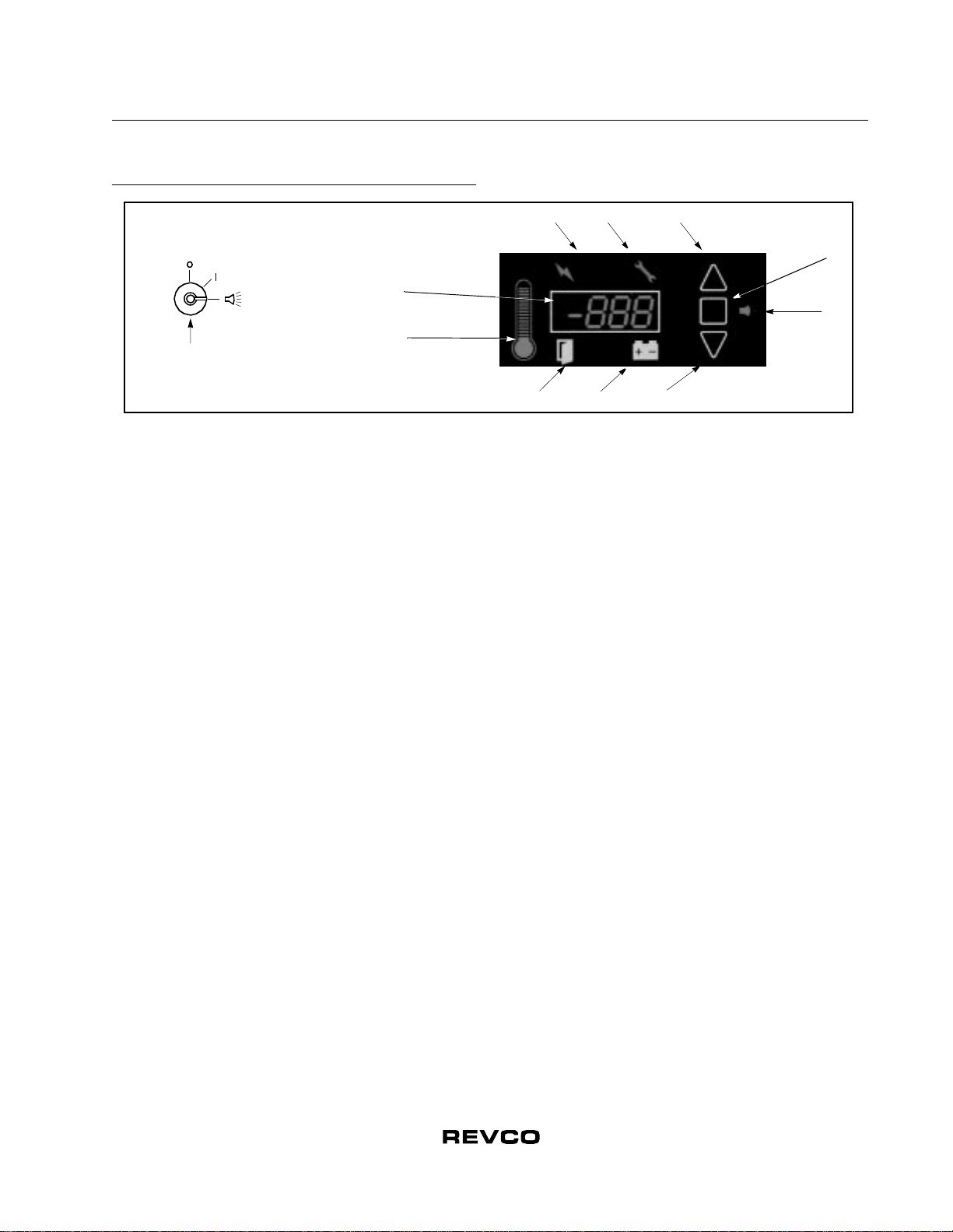
The alarm system is activated only when the key switch is turned
to the Alarm On position. The audible warning signal sounds
when there is a power failure or temperature alarm condition, or
when the door is ajar for more than 2 minutes.
The Mute function (pressing the button) allows you to turn off
the audio warning without turning off the visual indicators.
9.2 Local and Remote Alarms
Blood bank units can have either a factory-installed local alarm
or an optional user-installed remote alarm. Operating and testing
procedures are the same for both types of alarm.
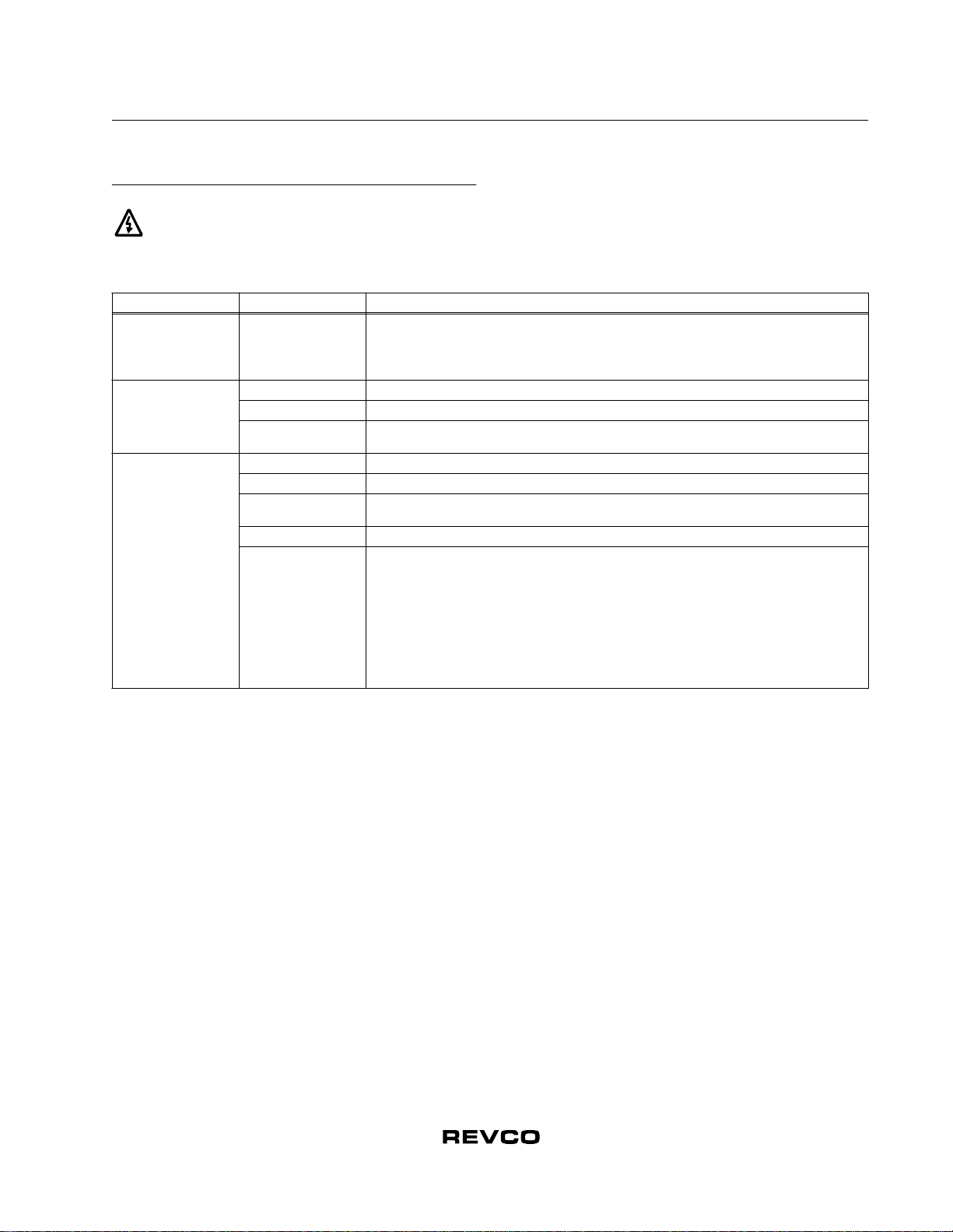
The maximum distance between a blood bank and a remote
alarm depends on the wire gauge used. Refer to Table 5 below.
Table 5. Wire Gauges and Distance to Remote Alarm
9.3 Installing a Remote Alarm (Optional)
Remote alarm terminals are located at the rear of the machine
compartment. The terminals are: Common, Open on Fail
(Normally Closed), and Close on Fail (Normally Open).
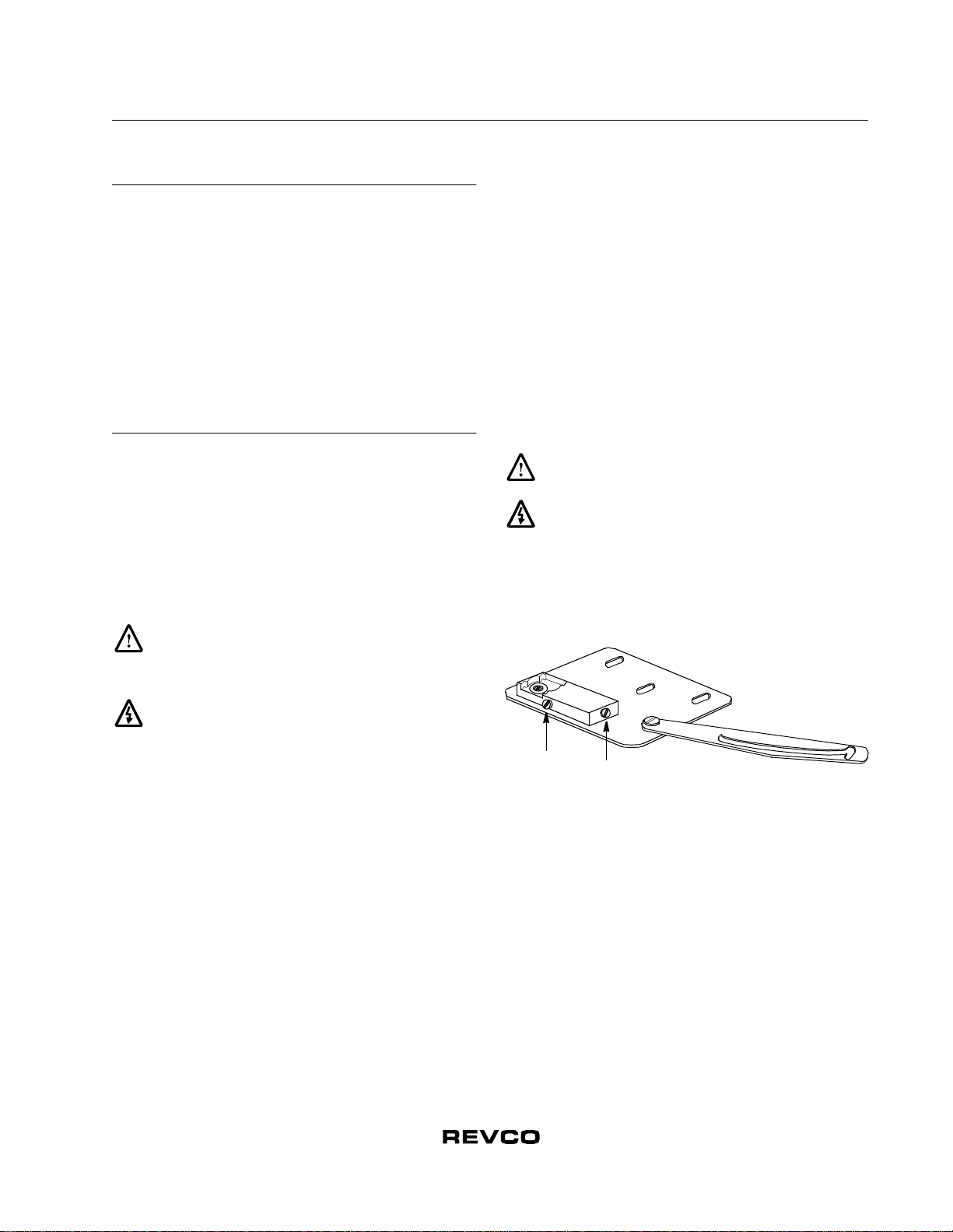
1. The remote alarm system has two keyhole slots on the back
to hang the alarm system on the wall. Insert two screws, no
longer than a #12 truss-head type and spaced two inches
apart, into a wall and mount the alarm.
2. Make the following connections:
a. Connect the common terminal on the cabinet switch to
the purple wire on the alarm.
b. Connect the normally closed terminal on the cabinet to
the black (“open on fail”) wire on the alarm. This
connection gives an alarm when the switch contacts open.
3. Plug the alarm system service cord into an electrical outlet.
This alarm is designed for 115V/60 Hz, 115V/50 Hz, or
100V/50 Hz operation.
Note: If you want the alarm signal to sound when the switch
contacts close, connect the normally open terminal on
the cabinet to the red/white (“close on fail”) wire on the
alarm. The purple and red/white wires must be tied
together in this application.
The wiring diagram is attached to the inside of the alarm back
cover.
9.4 Alarm Test
Note: It is important to test your alarm system after any
maintenance operation or temperature control
adjustment.
9.4.1 Theory of Operation
This test procedure applies to both factory-installed built-in
alarms and optional field-installed remote alarms.
During the alarm test, the temperature sensor is artificially heated
and cooled by a tiny, built-in thermoelectric heating and cooling
unit which simulates both warm and cold conditions. The
electronic control module notes the sensor temperature changes
and the control panel displays these changes.
While this alarm testing procedure is very accurate and reliable,
the temperature of the refrigerated space does not change during
the alarm test.
9.4.2 Alarm Test Procedure
Note: This test automatically advances through all steps and
stops.
1. Verify that the current warm and cold alarm setpoints are
within normal ranges (the warm and cold simulations may
not work if the setpoints are set to extreme values).
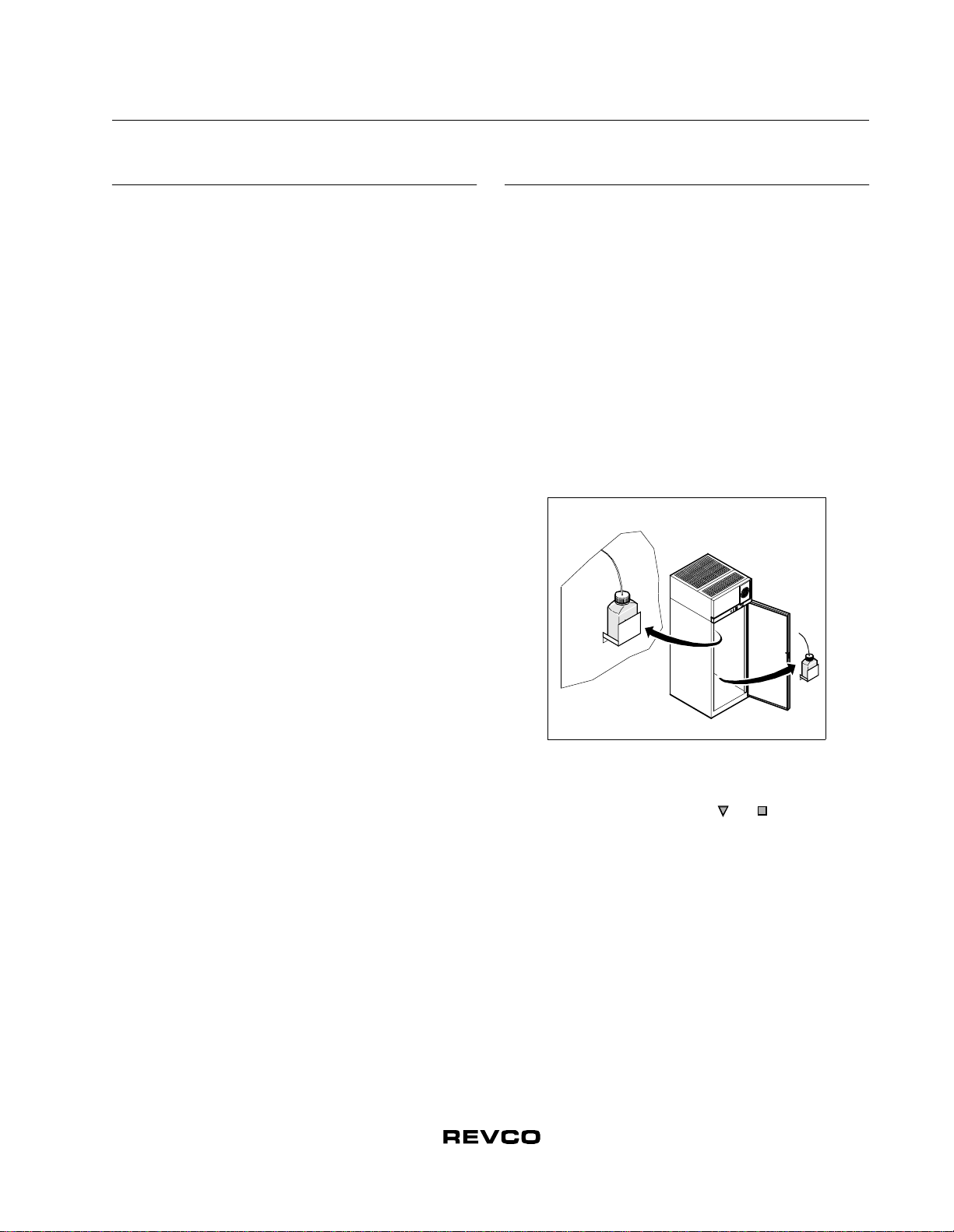
2. To start the alarm test, press and simultaneously and
hold for five seconds. During the test the main display and
thermometer bulb will indicate simulated (not actual) cabinet
temperature.
3. When simulated temperature exceeds the warm alarm
setpoint, the alarm sounds and the alarm icon on the control
panel illuminates (#10 in Figure 3 on page 4).
4. The temperature display begins to drop. After a few seconds,
the temperature in the display is back in the operating range.
5. The alarm stops. The temperature on the display drops until
the cold alarm sounds.
6. The test is now complete but the alarm continues to sound
until the temperature on the display is back in the operating
range.
If the simulated alarm conditions do not occur during the first 10
minutes of the alarm test, the service (wrench) icon illuminates
and the test is terminated. When during the alarm test, the
temperature display does not change or the service icon
illuminates, check the sensor connections.
You can terminate the alarm test at any point by pressing the
button.
Wire Gauge Total Wire Length
(feet)
Distance to Alarm
1/2 Wire Length
(feet)
20 530 265
18 840 420
16 1,330 665
14 2,120 1,060
12 3,370 1,685

8
Installation and Operation
Blood Bank Refrigerators
10 Chart Recorders
Panel-mounted six inch recorders are standard and factory-
installed on all models. Recorder operation begins when the
system is powered on.
10.1 Set Up and Operation
To prepare the recorder to function properly, complete the
following steps:
1. Open the recorder door to access the recorder.
2. Connect the nine volt DC battery located at the recorder’s
upper right corner. This battery provides back-up power.
3. Install clean chart paper (refer to Section 10.3 below).
4. Remove the plastic cap from the pen stylus and close the
recorder door.
Note: The recorder may not respond until the system reaches
temperatures within the recorder’s range.
Figure 5. Six Inch Chart Recorder
Figure 6. Chart Buttons
10.2 Power Supply
The recorder normally uses AC power when the system is
operating. If AC power fails, the LED indicator flashes to alert
you to a power failure. The recorder continues sensing cabinet
temperature and the chart continues turning for approximately
24 hours with back-up power provided by the nine-volt battery.
The LED indicator glows continuously when main power is
functioning and the battery is charged.
When the battery is low, the LED flashes to indicate that the
battery needs to be changed.
10.3 Changing Chart Paper
To change the chart paper, complete the following steps:
1. Locate the pressure sensitive buttons at the front, upper left
of the recorder panel.
2. Press and hold the change chart button for one second. The
pen will move off the scale.
3. Unscrew the center nut, remove the old chart paper, and
install new chart paper. Carefully align the day and time with
the reference mark on the recorder panel (a small groove on
the left side of the panel, shown in Figure 5).
4. Replace the center nut and hand tighten. Press the change
chart button again to resume temperature recording.
10.4 Calibration Adjustment
This recorder has been accurately calibrated at the factory and
retains calibration even during power interruptions. If required,
however, adjustments can be made as follows:
1. Run theunit continuously at the control setpoint temperature.
Continue steady operation for at least two hours to provide
adequate time for recorder response.
2. Measure cabinet center solution temperature with a
calibrated temperature monitor. (Solution temperature is
measured inside the sensor bottles — see Section 8.2.)
3. Compare the recorder temperature to the solution
temperature. If necessary, adjust recorder by pressing the left
(#1) and right (#2) chart buttons.
Note: The stylus does not begin to move until the button is held
for five seconds.
9 Volt Battery
Imprinting
Stylus
Hub-Nut and
Retaining Wire Chart
Chart Buttons
12
3
CHANGE CHART

9
Installation and Operation
Blood Bank Refrigerators
11 Cleaning
11.1 Cleaning the Drawers and Cabinet Interior
To clean the drawers and cabinet interior, remove the drawers
following the instructions in Section 5. Use a solution of water
and amild detergent. Rinsethe drawers andwipe them dry with a
soft cloth.
11.2 Cleaning the Condenser
WARNING! Disconnect equipment from main
power before attempting any maintenance to
equipment or its controls.
CAUTION! Condensers should be cleaned at least
every six months. In heavy traffic areas, condensers
load with dirt more quickly. Failure to keep the
condenser clean can result in equipment warm-up or
erratic temperatures.
CAUTION! Never clean near condensers with your
fingers. Some surfaces are sharp.
Periodically check the condenser to make sure that it is clean.
In all models, the condenser is located in the top machine
compartment. To clean the condenser:
1. Disconnect the power.
2. Remove the top grill.
3. Use a vacuum cleaner with hose and brush attachments to
clean the front face of the finned surface.
4. Clean up any loose dust and replace the grill.
5. Reconnect the power.

10
Installation and Operation
Blood Bank Refrigerators
12 Troubleshooting
WARNING! Troubleshooting procedures involve working with high voltages which can cause injury or death.
Troubleshooting should only be performed by trained personnel.
This section is a guide to troubleshooting equipment problems.
Table 6. Troubleshooting Procedures
Problem Cause Solution
Unit does not operate
or Power Failure
Indicator is on. Power supply
1. Check that the cord is securely plugged in.
2. Plug another appliance into the outlet to see if it is live.
3. Test the voltage and verify that it is correct for your unit (refer to Table 1 on page 1).
4. If the outlet is dead, check the circuit breaker or fuses.
Temperature
fluctuates.
Cold control Make sure that the cold control is set correctly. Refer to Section 8 on page 6.
Condenser Make sure the condenser is clean. Refer to Section 11.2 on page 9.
Other causes If the cold control is set correctly, the condenser is clean, but temperature continues to fluctuate, call
an authorized Revco service representative.
Unit warms up.
Door is open Make sure the door is completely closed.
Door seal Check the door seal, following instructions in Section 4.5 on page 3.
Warmproductrecently
loaded in unit Allow ample time to recover from loading warm product.
Power supply Check for proper voltage to the unit. If there is no voltage to the unit, call an electrician.
Compressor
1. If the compressor is not running and the power failure alarm light is on, have an electrician
check for proper voltage to the unit.
2. If the compressor is not running and the power failure alarm light is off, call the technical
support hot line.
3. If the compressor is running, open the door and look through the slotted air intake in the bottom
of the evaporator cover to see if icing is present on the evaporator. If icing is present and there
is no air flow behind evaporator, call technical service for assistance. The evaporator fans may
be inoperative.
4. If the compressor is running and there is airflow behind the evaporator, contact an authorized
service provider or call the technical support hot line for assistance.

11
Installation and Operation
Blood Bank Refrigerators
13 Optional Accessories
Remote Alarm. Optional for all blood bank models.
Temperature Recorders
All six inch recorders use pressure-sensitive chart paper
(1 box @ 50 charts included); no inking is required. Four inch
recorders use inked marker pens.
Chart Paper
Low Voltage Protection
Casters
Description Catalog
No.
Standard Remote Alarm. Provides audible and visual
signal in the event of temperature rise or power failure.
Adaptable to telephone switchboard. Can be located
up to 1/3 mile (1760 ft/536 m) from cabinet. Must be
used with electronic alarm system and connected to
normally-open or normally-closed remote alarm
contacts. Wire not included. Specify voltage when
ordering. 5612
Deluxe Electronic Remote Alarm System. User
programmable to sound alarm in the event of
temperature rise or power failure. Can dial up to four
telephone numbers to advise of alarm condition
across any telephone system which accepts pulse
dialing. One system can monitor up to four individual
cabinets. In addition, the system can monitor up to
three groups of cabinets. Contact Revco for detailed
specifications. Customer installed. 6224
Description Catalog
No.
Temperature recorder, 6 in. circular chart, seven-day drive,
free-standing. Customer installed. Specify voltage
when ordering. 6383-7
Description Catalog
No.
Chart paper, package of 50, for six inch, seven-day
recorder, -40°C to +25°C. 6184
Chart paper, package of 50, for four inch, seven-day
recorder, -40°C to +50°C. 6198
Description Catalog
No.
Voltage Safeguard. Free-standing. Helps protect
electrical equipment from damage by boosting low
voltage automatically. Provided with terminal board for
direct wiring. Field installed. Specify voltage when
ordering. 5575
Description Catalog
No.
Caster Dolly. For use with 5.4 cu.ft and 11.5 cu.ft
cabinets. 6174
Dual-Wheel Casters. Set of four, 2 in. diameter, for 23.3,
29.2, and 51.1 cu.ft models only. 6041

12
Installation and Operation
Blood Bank Refrigerators
14 Warranty
14.1 Domestic Warranty
13 Months Full Warranty, Parts and Labor
United States of America and Canada
Revco Scientific, Inc. warrants this product to the owner for a
period of thirteen (13) months from date of shipment by Revco
Scientific, Inc. Under this warranty, Revco, through its
authorized service organizations, will repair, or at its option,
replace any part found to contain a manufacturing defect in
material or workmanship without charge to the owner for parts,
service labor, or any shipping or cartage costs. Replacement or
repaired parts will be warranted for only the unexpired portion of
the original warranty. This warranty is limited to products
purchased and installed in the United States of America and
Canada. It does not apply to damage caused by accident, misuse,
fire, flood, or acts of God. It does not apply to damage caused
from failure to properly install, operate, or maintain the product
in accordance with the printed instructions provided.
To obtain prompt warranty service, simply contact the nearest
authorized service center or dealer listed in the directory
enclosed with each product. Revco’s own shipping records
showing date of shipment shall be conclusive in establishing the
warranty period.
This warranty is in lieu of any other warranties, expressed or
implied, including merchantability or fitness for a particular
purpose. The owner agrees that Revco’s sole liability with
respect to defective parts shall be as set forth in this warranty,
and any claims for incidental or consequential damages are
expressly excluded.
14.2 International Warranty
16 Month Parts Warranty
Revco Scientific, Inc., warrants this product to the owner for a
period of sixteen (16) months from the date of shipment by
Revco. If any part is found to contain a manufacturing defect in
material or workmanship, Revco assumes no responsibility for
any labor expenses for service, removal, or reinstallation
required to replace part, or for incidental repairs, and such costs
are the responsibility of the Owner unless a service labor
agreement exists between the Owner and his Dealer.
The warranty does not apply to damage caused by accident,
misuse, fire, flood, or acts of God, or to defects resulting from
failure to properly install, operate, or maintain the product in
accordance with the printed instructions provided.
To obtain prompt warranty service. simply contact the Dealer
from whom you purchased the product or the nearest Dealer
handling Revco products. Revco’s own shipping records
showing date of shipment shall be conclusive in establishing the
warranty period.
This warranty is in lieu of any other warranties, expressed or
implied, including merchantability or fitness for a particular
purpose. The owner agrees that Revco’s sole liability with
respect to defective parts shall be as set forth in this warranty,
and any claims for incidental or consequential damages are
expressly excluded.
14.3 Extended Warranty Options
In addition to Revco’s standard 13-Month full warranty on the
complete product (USA and Canada), Revco can supply an
additional four year protection on compressor and compressor
parts. This additional coverage must be purchased at the time of
original product purchase. Under this contract, Revco Scientific
agrees to furnish a compressor FOB our factory to replace one
which has been determined to be defective by Revco or a factory
authorized Revco Service Agency.
Description Catalog
No.
Extended Four-Year Compressor Parts Contract, all
refrigerators. 6069
Extended 12-Month Comprehensive Coverage, for all
models, provides additional 12-month warranty
coverage, parts and labor. Contact Revco for details. 6613

For your future reference and when contacting the factory, please have the
following information readily available:
Model Number:
Serial Number:
Date Purchased:
The above information can be found on the dataplate attached to the
equipment. If available, please provide the date purchased, the source of
purchase (Revco or specific agent/rep organization), and purchase order
number.
If You Need Assistance
REVCO SALES DIVISION
Phone: 828/658-2711
800/252-7100
FAX: 828/645-3368
LABORATORY PARTS and SERVICE
Phone: 800/438-4851
FAX: 828/658-2576
TECHNICAL SUPPORT
Phone: 800/438-4851
275 Aiken Road
Asheville, NC 28804
U.S.A.
This manual suits for next models
3
Table of contents