manuals.online logo
Brands
  1. Home
  2. •
  3. Brands
  4. •
  5. Reznor
  6. •
  7. Furnace
  8. •
  9. Reznor XE Series User manual

Reznor XE Series User manual

Form I-XE/CRGB/RPB, Mfg No. 131782 Rev 4, Page 1
®
Installation/Operation/Maintenance
FormI-XE/CRGB/RPB(VersionB)
ObsoletesFormI-XE/RGB/RPB(VersionA)
Model Series XE, CRGB, RPB
Packaged Duct Furnace
Assemblies
Index by Page Number
GENERAL
Installation should be done by a qualified agency in accordance with the instructions in this
manual and in compliance with all codes and requirements of authorities having jurisdiction.
The instructions in this manual apply to the packaged systems listed below.
FORYOURSAFETY
If you smell gas:
1.Openwindows.
2.Don'ttouch electrical switches.
3.Extinguishanyopenflame.
4.Immediatelycall yourgassupplier.
FORYOURSAFETY
Theuseandstorageofgasolineorotherflammablevaporsandliquidsin
opencontainersinthevicinity of this applianceishazardous.
WARNING: Improper installation, adjustment, alteration, service, or
maintenance can cause property damage, injury or death. Read the
installation,operation,andmaintenanceinstructionsthoroughlybefore
installingorservicingthisequipment.
WARNING: Gas-fired appliances are not designed for use in hazardous
atmospheres containing flammable vapors or combustible dust, in
atmospheres containing chlorinated or halogenated hydrocarbons, or in
applicationswithairbornesiliconesubstances.SeeHazardLevels,Page2.
Table of Contents Para. Page
Installation and Operation ......... 1-29 ... 1-30
Check Installation and Start-Up ... 30 . 30-31
Optional Accessories ................. 31-36 . 31-41
Service/Maintenance .................. 37-41 . 41-44
Adjusting Blower Speed ............................... 24
Optional Air Flow Proving Switch .............. 24
Opt High Ambient Limit Control .................. 25
AquaSaver Timer Adjustment ........................ 34
Belts ...............................................................24
Blocked Vent Switch ...................................... 25
Blower Motors ............................................... 24
Blower Rotation ............................................. 24
Burner Air Adjustment .................................. 30
Burner Rack Removal ..................................... 42
Burners ........................................................... 29
Carryover System ........................................... 29
Check Installation and Start-Up ....................30
Chlorines .......................................................... 7
Cleaning Pilot and Main Burners .................. 42
Cleaning the Heat Exchanger ........................ 42
Clearances ........................................................ 7
Optional Cooling Coil Cabinet ..................... 38
Combustion Air Requirements ........................ 7
Condensate Drain .......................................... 13
Location of Controls ...................................... 17
Cooling Coil Cabinet .................................... 38
Optional Dampers and Controls ....................35
Dimensional Data ............................................ 3
Direct Digital Control System ....................... 29
Discharge Dampers ........................................ 39
Disconnect Switch ......................................... 17
Duct Connections .......................................... 13
Optional Ductstat .......................................... 26
Electrical Supply and Connections ............... 16
Optional Electronic Modulation .................. 26
Opt Evaporative Cooling Module ................ 32
Optional Fan Control .................................... 25
Optional Dirty Filter Switch ......................... 38
Filter Arrangements .......................................38
Optional Filter Rack and Filters .................... 37
Gas Piping and Pressures .............................. 14
Gas Valve ........................................................ 41
General ............................................................. 1
Hazard Intensity Levels ................................... 2
Ignition Controller ......................................... 29
Installation Codes ............................................ 2
Limit Control .................................................24
Manifold Pressure Setting ............................. 15
Optional Mechanical Modulation ................. 26
Mounting Furnaces (Indoor) ........................... 8
Mounting Outdoor Models ............................. 8
Optional Equipment ...................................... 31
100% Outside Air Hood ................................31
Pilot and Ignition Systems ............................ 29
Reverse Flow, Limit Control .......................... 25
Roof Curb Assembly and Installation .............. 9
30% Screened Air Hood Opening ................ 32
Optional 4-foot Stack Extension ................... 12
Start-Up .......................................................... 30
Suspending Furnaces ....................................... 8
Troubleshooting ............................................43
Optional Two-Stage Operation ..................... 25
Uncrating ......................................................... 2
Valve ............................................................... 25
Variable Frequency Drive .............................. 24
Vent Cap Installation .....................................12
Optional Power Venting ................................ 12
Venting ........................................................... 11
Venting Requirements .................................... 11
Optional Vertical Flue Discharge .................. 13
Warranty ........................................................... 2
Wiring Diagrams ............................................18
Characteristics
Installation Vent CFM Thermal
Efficiency
XE Standard
HXE High
CRGB Standard
HCRGB High
RPB Standard
HRPB High
80%
Model Series
Designation
Power
Indoor
Outdoor
Gravity
Form I-XE/CRGB/RPB, Page 2
1. Approval and Installation Codes
The models covered in this manual are design certified or approved duct
furnaces that are factory assembled with air handing components, creat-
ing a unified packaged furnace/blower system. The packaged system
models listed on page 1 are design-certified toANSI and CSAStandards
by the Canadian Standards Association. All models are approved for
installation in the United States. All models except Model CRGB and
Model HCRGB are approved for installation in Canada.All furnaces are
approved for use with either natural gas or propane. The type of fuel for
which the furnace is equipped and the correct firing rate are shown on
the rating plate attached to the unit. Electrical characteristics are shown
on both the motor nameplate and the unit rating plate.
These units must be installed in accordance with local building codes. In
the absence of local codes, in the United States, the unit must be in-
stalled in accordance with the National Fuel Gas Code NFPA54/ANSI
Z223.1 (latest edition). A Canadian installation must be in accordance
with the CSA B149.1 Natural Gas and Propane Installation Code. These
codes are available from CSA Information Services, 1-800-463-6727.
Localauthoritieshavingjurisdictionshould be consulted before installa-
tion is made to verify local codes and installation procedure require-
ments.
Special Installations (Aircraft Hangars/Garages)
Installations in aircraft hangars should be in accordance with NFPANo.
409 (latest edition), Standard forAircraft Hangars; in public garages in
accordance with NFPA No. 88A (latest edition), Standard for Parking
Structures; and for repair garages in accordance with NFPA No. 88B
(latest edition), Standard for Repair Garages. In Canada, installations in
aircraft hangars should be in accordance with the requirements of the
enforcing authorities, and in public garages in accordance with CSA
B149.1 codes.
WARNING: To ensure safety, follow the lighting
instructions located on the outlet box cover plate
in the heater section of the packaged furnace
assembly.
HAZARDINTENSITYLEVELS
usedforWarningsinthisManual
1. DANGER:Failuretocomplywillresultin
severepersonalinjuryordeathand/or
propertydamage.
2. WARNING:Failuretocomplycouldresultin
severepersonalinjuryordeathand/or
propertydamage.
3. CAUTION:Failuretocomplycouldresultin
minorpersonalinjuryand/orpropertydam-
age.
WARRANTY:Warranty is void if......
a. Packaged furnacesareusedinatmospheres containing
flammablevaporsoratmospherescontaining
chlorinatedorhalogenatedhydrocarbonsorany
contaminant(silicone,aluminiumoxide,etc.)that
adherestothe sparkignitionflamesensing probe.
b. Wiringisnotin accordance withthediagramfurnished
withtheheater.
c. Unitisinstalledwithoutproperclearancesto
combustiblematerialsorwithoutproperventilationand
airforcombustion.(See Paragraphs 5and 6.)
d. Furnaceairthroughputisnotadjustedwithintherange
specifiedontheratingplate.
3. Uncrating and Preparation
This furnace was test operated and inspected at the factory prior to
crating and was in operating condition. If the equipment has incurred
any damage in shipment, document the damage with the carrier and
contact your Reznor distributor.
Check the rating plate for the gas specifications and electrical character-
istics of the furnace to be sure that they are compatible with the gas and
electric at the installation site. Read this booklet and become familiar
with the installation requirements of your particular model. If you do
not have knowledge of local requirements, check with the local gas
company or any other local agencies who might have requirements
concerning this installation. Before beginning, make preparations for
necessary supplies, tools, and manpower.
Check to see if there are any field-installed options that need to be
assembled to the furnace prior to installation.
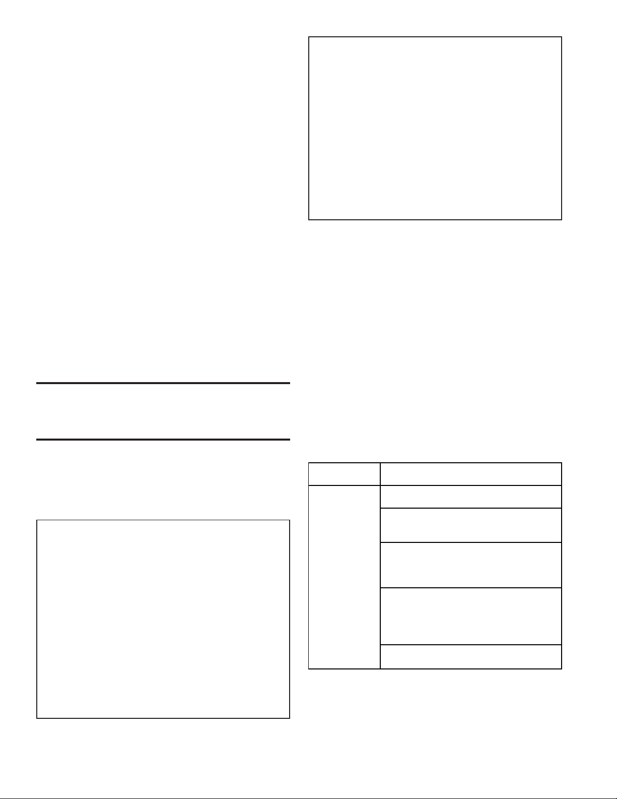
Option Parts - Some gas control options will have parts either shipped
loose with the heater or shipped separately. If your unit is equipped
with any of the following gas control options, be sure these parts are
available at the job site.
Other shipped-separate options could include a roof curb, a cooling coil
cabinet, a screened outside air hood, a gas shutoff valve, a condensate
drain fitting, a thermostat, a different control switch, a power venter, a
remote console, a manual fan switch, a vertical vent terminal, a gas
supply regulator, and/or a disconnect switch. Or, if equipped with an
optionalevaporative cooling module, awater hammer arrestor orfill and
drain or freeze kit could be shipped separately.
Heatin
g
-- Gas O
p
tion AG7
Control O
p
tion Thermostat, P/N 48033
Makeu
p
Air -- O
p
tion AG3, AG6, AG8 or AG13
Gas Control Control Switch, P/N 29054
O
p
tions O
p
tion AG9
Remote Temperature Selector, P/N 48042
(If an o
p
tional Control Switch, P/N 29054
remote console O
p
tion AG15
is ordered, the Remote Temperature Selector, P/N 115848
control switch Stage Adder Module, P/N 115849
is mountedon Control Switch, P/N 29054
the console.) O
p
tion AG16
Remote Temperature Selector, P/N 115848
Stage Adder Module, P/N 115849
Remote Display Module, P/N 115852
Control Switch, P/N 29054
Option AG39
Remote Temperature Selector, P/N 174849
2. Warranty
Refer to limited warranty information on the warranty card in the
"Owner's Envelope".
Form I-XE/CRGB/RPB, Mfg No. 131782 Rev 4, Page 3
4. Dimensions
FIGURE1A-Dimensions(inchesandmm)ofIndoor/GravityVentedSystem
3/4 (19)
JGF
B
WCX
K
A
59 (1499)
4 (102)
2-1/8
(54)
Blower Furna e
Gas
Top View Side View
AIRFLOW
Control Wiring
Entran e
Supply Wiring
Entran e
Furna eBlower
E18
(457)
3/4 (19)
H
K
3-5/8 (92)
8 (203)
3/4
(19)
(4)Mounting So kets
1 IPS free turning
female pipe thread
1-3/4 (44)
JGF
B
WCX
K
A
60 (1524)
4 (102)
2-1/8
(54)
Blower
Furna e
Gas
Top View Side View
AIRFLOW
Control Wiring
Entran e
Supply Wiring
Entran e
Furna eBlower
19-1/2
(495)
18
(457)
3/4 (19)
H
K
3-5/8 (92)
8 (203)
3/4
(19)
(4)Mounting So kets
1 IPS free turning
female pipe thread
C
3-1/4 (83)
D
19-1/2
(495)
3-1/4 (83)
Verti al return air
opening is apped
at the fa tory.
DimensionsofModel (H)XEwith Standard BlowerCabinet (Standard blower cabinethas "fullopen" endandwill not accommo-
date dampers.An optional cabinet is available with a smaller horizontal inlet that will accommodate dampers; see dimensional
drawing below.An optional bottom inlet will also accommodate dampers.)
DimensionsofModel (H)XE withOptional BlowerCabinet (Optionalblower cabinethas ahorizontal inletthat will accommodate
dampers. The cabinet also has a bottom inlet that is shipped with a cap; the bottom inlet will accommodate dampers.)
Dimension Key:
A x 18" (457mm) = Discharge Opening
B= Hanger Centerline - Furnace Section
C x E = Return Air Opening with Standard Cabinet
C x 19-1/2" (495mm) = Return Air Openings with Optional Cabinet
X= Hanger Centerline - Standard and Optional Blower Cabinet
Dimensions (inches andmm) - Gravity-Vented/Indoor Models XE/HXE
Gas Connection
Natural Propane
inches 12-1/2 13-1/2 17-3/8 9-1/2 27-3/4 18 1/2 1/2 3-3/4 32-1/4 36-1/2 5 Rd 22 16-1/4
mm 318 343 441 241 705 457 13 13 95 819 927 127 Rd 559 413
inches 12-1/2 13-1/2 17-3/8 9-1/2 27-3/4 18 1/2 1/2 3-3/4 32-1/4 36-1/2 6 Rd 22 16-1/4
mm 318 343 441 241 705 457 13 13 95 819 927 152 Rd 559 413
inches 15-1/4 16-1/4 17-3/8 9-1/2 27-3/4 18 1/2 1/2 3-3/4 32-1/4 36-1/2 7 Ov 22 16-1/4
mm 387 413 441 241 705 457 13 13 95 819 927 178 Ov 559 413
inches 20-3/4 21-3/4 23 9-1/2 27-3/4 19-3/8 1/2 1/2 2-3/8 32-1/4 36-1/2 8 Ov 27-1/2 21-3/4
mm 527 552 584 241 705 492 13 13 60 819 927 203 Ov 699 552
inches 26-1/4 27-1/4 28-3/8 12-1/2 30-3/4 18 1/2 1/2 2-1/4 35-1/4 38 8 Rd 33 27-1/4
mm 667 692 721 318 781 457 13 13 57 895 965 203 Rd 838 692
inches 34-1/2 35-1/2 36-5/8 12-1/2 30-3/4 18 1/2 1/2 2-1/4 35-1/4 38 10 Ov 41-1/4 35-1/2
mm 876 902 930 318 781 457 13 13 57 895 965 254 Ov 1048 902
inches 34-1/2 35-1/2 36-5/8 12-1/2 30-3/4 18 3/4 1/2 2-1/4 35-1/4 38 10 Ov 41-1/4 35-1/2
mm 876 902 930 318 781 457 19 13 57 895 965 254 Ov 1048 902
inches 40 41 42-1/8 12-1/2 30-3/4 19-3/8 3/4 1/2 7/8 35-1/4 38 12 Ov 46-3/4 41
mm 1016 1041 1070 318 781 492 19 13 22 895 965 305 Ov 1187 1041
inches 45-1/2 46-1/2 47-5/8 12-1/2 30-3/4 18 3/4 1/2 2-1/4 35-1/4 38 12 Ov 52-1/4 46-1/2
mm 1156 1181 1210 318 781 457 19 13 57 895 965 305 Ov 1327 1181
100
125
ABSize
75
350
400
150,
175
200,
225
250
300
CDEF WXGH J K
Form I-XE/CRGB/RPB, Page 4
4. Dimensions (cont'd)
86-11/16 (2202)
Blower
Cabinet Furna e
Airflow
Field Control
Wiring
Entran e
39-3/16*
(995)
Optional
Downturn
Plenum
Cabinet
A
38-1/8*
*
(968)
Field Wiring
(line voltage)
Gas Curb Cap
C
B
38-5/8 (981)
4-3/32
(104) 19-1/2
(495)
19-1/2
(495)
85-13/16 (2180)
Optional
Return
Air Inlet
Verti al
Dis harge
1-1/32
(26)
4-1/4
(108) 4-1/4
(108)
Left Side View with Verti al Dis har
g
e
Front View with
Opt ional Verti al Dis harge
(Downturn Plenum Option AQ5 or AQ8)
4-3/32
(104)
5 (127)
19-1/2
(495)
4-5/8
(117)
31-11/32
(796)
43-17/32 (1106)
S reened
Outside
Air Hood -
Option AS2
5 (127)
19-1/2
(495) Blower
Cabinet
1-1/32 (26) 61-3/8 (1559)
Control Wiring
Entran e
Furna e
Airflow
8-1/2(215)
11-1/4(286)
18
(457)
3/4(19)
3/4(19)
39-3/16*
(995)
Curb Cap
Gas
Field Wiring
(line voltage)
61-7/8 (1572)
A
38-1/8**
(968)
3/4(19) 3/4(19)
D
B
C
Left Side View with Horizontal Dis harge Front View with
Standard Horizontal Dis harge
NOTES:
*Height from top of
cabinet to top of curb
cap.
**Height from top of
cabinet to bottom of
cabinet side.
*** If system has a cooling
coil cabinet, add length
dimension on page 6 for full
system length.
**** The two-position
discharge dampers in
Option AQ8 fit in the
discharge air opening. The
damper motor fits inside the
downturn plenum cabinet.
For dimensions with
downturn plenum cabinet
with a cooling coil cabinet,
see page 6.
FIGURE1B-
Dimensions,
Outdoor/
Gravity-
VentedModel
SeriesCRGB
Vent Cap Gas Connection
I.D. Height Extension Natural Propane
inches 28-5/8 17-3/8 25-7/8 12-1/2 6 9 None 1/2 1/2
mm 727 441 657 318 152 229 None 13 13
inches 28-5/8 17-3/8 25-7/8 15-1/4 8 11-1/2 None 1/2 1/2
mm 727 441 657 387 203 292 None 13 13
inches 34-1/8 22-7/8 31-3/8 20-3/4 8 11-1/2 None 1/2 1/2
mm 867 581 797 527 203 292 None 13 13
inches 39-5/8 28-3/8 36-7/8 26-1/4 10 15 None 1/2 1/2
mm 1006 721 937 667 254 381 None 13 13
inches 47-7/8 36-5/8 45-1/8 34-1/2 10 15 None 1/2 1/2
mm 1216 930 1146 876 254 381 None 13 13
inches 47-7/8 36-5/8 45-1/8 34-1/2 10 15 None 3/4 1/2
mm 1216 930 1146 876 254 381 None 19 13
inches 53-3/8 42-1/8 50-5/8 40 12 14-1/8 plus 12 3/4 1/2
mm 1362 1070 1286 1016 305 359 plus 305 19 13
inches 58-7/8 47-5/8 56-1/8 45-1/2 12 14-1/8 plus 12 3/4 1/2
mm 1470 1210 1426 1156 305 359 plus 305 19 13
Standard Horizontal Air Inlet 19-1/2 (495) x B
Optional Return Air Opening (bottom) 19-1/2 (495) x B
Standard Horizontal Discharge Air Opening 18 (457) x D
Optional Vertical Discharge Air Opening(Option AQ5 or AQ8 Downturn Plenum****) 19-1/2 (495) x B
**** for downturn plenum with coolingcoil cabinet, see page 6.
75,
100
125
175
225
250
300
350
CRGB,
HCRGB
D
Model
Series
Air O
p
enin
g
Dimensions
Size ABC
400
Form I-XE/CRGB/RPB, Mfg No. 131782 Rev 4, Page 5
86-11/16 (2202)
Blower
Cabinet
Furna e
Airflow
Field Control
Wiring
Entran e
39-3/16*
(995)
Optional
Downturn
Plenum
Cabinet
A
38-1/8**
(968)
Field Wiring
(line voltage)
Gas Curb Cap
C
B
38-5/8 (981)
4-3/32
(104) 19-1/2
(495)
19-1/2
(495) 85-13/16 (2180)
Optional
Return
Air Inlet
Verti al
Dis harge
1-1/32
(26)
4-1/4
(108) 4-1/4
(108)
Left Side View with Verti al Dis harge
Front View with
Opt ional Verti al Dis harge
(Downturn Plenum Option AQ5 or AQ8)
4-3/32
(104)
5 (127)
19-1/2
(495)
4-5/8
(117)
31-11/32
(796)
43-17/32 (1106)
S reened
Outside
Air Hood -
Option AS2
5 (127)
19-1/2
(495)
Blower
Cabinet
1-1/32 (26) 61-3/8 (1559)
Control Wiring
Entran e
Furna e
Airflow
Curb Cap
Gas
Field Wiring
(line voltage)
61-7/8 (1572)
A
38-1/8**
(968)
3/4(19) 3/4(19)
D
B
C
Left Side View with Horizontal Dis harge Front View with
Standard Horizontal Dis harge
3/4(19)
3/4(19)
39-3/16*
(995)
18
(457)
11-1/4(286)
8-1/2(215)
FIGURE1C-
Dimensions,Outdoor/
Power-VentedModel
Series RPB
NOTES:
*Height from top of
cabinet to top of curb
cap.
**Height from top of
cabinet to bottom of
cabinet side.
*** If system has a cooling
coil cabinet, add length
dimension on page 6 for full
system length.
**** The two-position
discharge dampers in
Option AQ8 fit in the
discharge air opening. The
damper motor fits inside
the downturn plenum
cabinet. For dimensions
with downturn plenum
cabinet with a cooling coil
cabinet, see page 6.
Gas Connection
Natural Propane
inches 28-5/8 17-3/8 25-7/8 15-1/4 1/2 1/2
mm 727 441 657 387 13 13
inches 34-1/8 22-7/8 31-3/8 20-3/4 1/2 1/2
mm 867 581 797 527 13 13
inches 39-5/8 28-3/8 36-7/8 26-1/4 1/2 1/2
mm 1006 721 937 667 13 13
inches 47-7/8 36-5/8 45-1/8 34-1/2 1/2 1/2
mm 1216 930 1146 876 13 13
inches 47-7/8 36-5/8 45-1/8 34-1/2 3/4 1/2
mm 1216 930 1146 876 19 13
inches 53-3/8 42-1/8 50-5/8 40 3/4 1/2
mm 1362 1070 1286 1016 19 13
inches 58-7/8 47-5/8 56-1/8 45-1/2 3/4 1/2
mm 1470 1210 1426 1156 19 13
AirOpenings: Dimensions
Standard Horizontal Air Inlet 19-1/2 (495) x B
Optional Return Air Opening (bottom) 19-1/2 (495) x B
Standard Horizontal Discharge Air Opening 18 (457) x D
19-1/2 (495) x B
****for downturn plenum with cooling coil cabinet, see page 6.
CD
Model Size AB
Optional Vertical Discharge Air Opening (with Option AQ5 or AQ8
Downturn Plenum****)
300
350
400
(H)-RPB
125
150, 175
200, 225
250
Form I-XE/CRGB/RPB, Page 6
D
7/8 (22) 7/8 (22)
2 (51)
Side View
DX Coil
Cabinet
Drain Pan
Outlet
(1 FPVC)
Su tion Line
Conne tion
(1-5/8 or 2-1/8)
14-1/2
(368)
6-5/8
(168)
G
F (Inside of Curb Cap)
E (Curb Cap Length)
Liquid Line
Conne tion Kno kouts
(alternate lo ations)
2-3/8
(60)
3-1/2(89)
3-1/4(83)
Bottom View
DX Coil
Cabinet
Coil
Header
Housing
Dimensions(inches ±1/8;mm± 3)
4. Dimensions (cont'd)
NOTE: For the length of a system with a cooling coil cabinet, see the
table on the left. Cooling coil cabinet is shipped separately and attached
in the field. See page 10 for roof curb dimensions.
Furnace Size 75, 100,
125 150,
175 200,
225 250,
300 350 400
inches 28-1/2 34 39-1/2 47-3/4 53-1/4 58-3/4
mm 724 864 1003 1213 1353 1492
inches 15-1/4 20-3/4 26-1/4 34-1/2 40 45-1/2
mm 387 52 667 876 1016 1156
inches 25-7/8 31-3/8 36-7/8 45-1/8 50-5/8 56-1/8
mm 657 797 937 1146 1286 1426
inches 37-1/8 42-5/8 48-1/8 56-3/8 62 67-3/8
mm 943 1083 1222 1432 1575 1711
inches 40 45-5/8 51 59-3/8 64-7/8 70-3/8
mm 1016 1159 1295 1508 1648 1788
inches 64 69-5/8 75 83-3/8 88-7/8 94-3/8
mm 1626 1768 1905 2118 2257 2397
inches 38-1/8 43-5/8 49-1/8 57-3/8 63 68-3/8
mm 968 1108 1248 1457 1600 1737
inches 62-1/8 67-5/8 73-1/8 81-3/8 87 92-3/8
mm 1578 1718 1857 2067 2210 2346
inches 19-1/2 22-1/4 25 29-1/8 31-7/8 34-5/8
mm 495 565 635 740 810 879
inches 17-3/8 22-7/8 28-3/8 45-1/8 50-5/8 56-1/8
mm 441 581 721 1146 1286 1426
A
B
C
D
E
F
G
J
Without
Downturn
With
Downturn
Without
Downturn
With
Downturn
ChilledWaterCoolingCoilCabinetinOptionsAU2,AU11,AU12
Refrigerant
R22(DX)
Coil
Cabinet-
Options
AU3,AU13,
AU14
DownturnPlenumCabinet(factoryattachedto
eithertypeofCoolingCoilCabinet)
Front View
DX Coil
Cabinet with
Horizontal
Dis harge
(Option AU3)
Liquid Line
Conne tions
(7/8 or 1-3/8)
5-1/8 (130)
8 (203)
3/4
(19)
3/4
(19)
A
B
3/4
(19)
18
(457)
44-1/4
(1124)
12-1/2
(318)
16-1/4
(413)
C
11-1/4
(286)
Side View
Chilled
Water Coil
Cabinet
F
(Inside of Curb Cap)
E
(Curb Cap Length)
D
7/8 (22)
Supply
Conne tion
2-1/2 NPT
G
7/8 (22)
Return
Conne tion
2-1/2 NPT
Coil Vent
1/2 NPT
Coil Drain
Conne tion
1/2 NPT
Drain Pan
Conne tion
1 FPVC)
6-5/8
(168)
38-3/8
(975)
15-1/4
(387)
Front View
CW Coil
Cabinet with
Horizontal
Dis harge
(Option AU2)
44-1/4
(1124)
18
(457)
3/4
(19)
11-1/4
(286)
C
A
B
3/4
(19)
Side View
Optional
Downturn
Plenum
Cabinet
4-1/4
(108)
19-1/2 (495)
Dis harge Air
J
(Dis harge Air)
C
Front View
Optional
Downturn
Plenum
Cabinet
Side View
Optional
Downturn
Plenum
Cabinet
4-1/4
(108)
4-1/4
(108)
Discharge Damper Note: Optional two-position discharge dampers
in Option AU12 or AU14 fit in the discharge air opening. The
damper motor fits inside the downturn cabinet. See field wiring
instructions in Paragraph 36.
FIGURE1D-
OptionalCooling
CoilCabinetswith
DXorChilled
WaterCoil, with
orwithout
DownturnPlenum
Cabinet(Applies
toOutdoor
Models)
inches mm inches mm inches mm inches mm
75, 100, 125 29-1/8 740 37-1/8 943 98-1/2 2502 121-5/8 3069
150, 175 34-5/8 879 42-5/8 1083 104 2642 127-1/2 3229
200, 225 40-1/8 1019 48-1/8 1222 109-1/2 2781 132-5/8 3369
250, 300 47-1/8 1197 55-1/8 1400 117-3/4 2991 140-7/8 3578
350 53-3/8 1356 61-3/8 1559 123-3/8 3134 146-1/2 3721
400 58-7/8 1495 66-7/8 1698 128-3/4 3270 151-7/8 3858
Model
Series
CRGB and
RPB Size
w/Cooling
Coil Cabinet
w/Downturn
w/Chilled
Water Coil
Cabinet
Width of Cabinets (not
curb )Length of All System
Cabinets (not curb )
w/DX Coil
Cabinet
w/Cooling
Coil Cabinet
only
Form I-XE/CRGB/RPB, Mfg No. 131782 Rev 4, Page 7
5. Clearances
Provide clearance to combustibles as shown in the table. Clearance to
combustibles is defined as the minimum distance from the heater to a
surface or object that is necessary to ensure that a surface temperature
of 90°F above the surrounding ambient temperature is not exceeded.
Clearance is also required to sides of furnace for combustion air space
and for convenient installation and burner control system service.
6. Combustion Air Requirements
6A. Indoor, Gravity-Vented Models XE/HXE
These furnaces are designed to take combustion air from the space in
which the furnace is installed. The air that enters into the combustion
process is vented to the outdoors. Sufficient air must enter the equip-
ment location to replace the air exhausted through the vent system.
Modern construction methods involve the greater use of insulation,
improved vapor barriers and weather-stripping, with the result that
buildings generally are much tighter structurally than they have been in
the past. The combustion air supply for gas-fired equipment can be
affected by these construction conditions because infiltration that would
have existed in the past may not be adequate. Extensive use of exhaust
fans aggravates the situation. In the past the filtration of outside air
assumedin heat loss calculations (oneair change per hour)was assumed
to be sufficient. However, current construction methods may now re-
quire the introduction of outside air through wall openings or ducts.
Requirementsfor combustionair andventilation airdepend uponwhether
the unit is located in a confined or unconfined space. An "unconfined
space" is defined as a space whose volume is not less than 50 cubic feet
per 1000 BTUH of the installed appliance. Under all conditions, enough
air must be provided to ensure there will not be a negative pressure
condition within the equipment room or space. A positive seal must be
madein all return-airconnections and ducts.Even a slightleak can create
a negative pressure condition in a confined space and affect combustion.
WARNING:Thesegravity-vented,indoorfurnaces
aredesignedtotakecombustionairfromthespace
inwhichthefurnaceisinstalledandarenotdesigned
for connection to outside combustion air intake
ducts. Use of outside air ducts voids the warranty
andcouldcause hazardous operation.See Hazard
Levels, page 2.
Indoor, Gravity-Vented Furnace Located in a
Confined Space
Do not install a unit in a confined space without providing wall open-
ings leading to and from the space. Provide openings near the floor and
ceiling for ventilation and air for combustion as shown in FIGURE 2,
depending on the combustion air source as noted in Items 1, 2 and 3.
Add total BTUH of all appliances in the confined space and divide by
figures below for square inch free area size of each (top and bottom)
opening.
1.Air from inside the building - openings 1 square inch free area per
1000 BTUH. Never less than 100 square inches free area for each open-
ing.See (1) inFIGURE 2.
2.Airfromoutsidethroughduct- openings 1 square inch free area per
2000 BTUH. See (2) in FIGURE 2.
3.Air direct from outside - openings 1 square inch free area per 4000
BTUH. See (3) in FIGURE2.
NOTE: For further details on supplying combustion air to confined
space, see National Fuel Gas CodeANSI Z223.1a (latest edition) 5.3.3.
6B. CombustionAir for Gravity-Vented,
Outdoor Model Series CRGB
Combustion air enters through the screened air intakes located in the
furnace section access doors.
6C. Combustion Air for Power-Vented,
Outdoor Model
Series RPB
The combustion air and flue gas
openings are carefully designed
screened openings located on the
side of the unit just above the con-
trol access panel. Location of the
flue opening directly above the air
intakeis designed todiscourage re-
circulation of combustion prod-
ucts.See FIGURE3.
6D. Chlorine -All Models
The presence of chlorine vapors in the combustion air of gas-fired heat-
ing equipment presents a potential corrosion hazard. Chlorine will,
when exposed to flame, precipitate from the compound, usually freon
or degreaser vapors, and go into solution with any condensation that is
present in the heat exchanger or associated parts. The result is hydro-
chloricacid which readily attacks allmetals including 300grade stainless
steel.
Care should be taken to separate these vapors from the combustion
process. This may be done by wise location of the furnace with regard
toexhausters orprevailing wind direction. Remember, chlorineis heavier
than air. This fact should be kept in mind when determining installation
locations of heating equipment and building exhaust systems.
7. Suspending/Mounting
7A. Suspending/Mounting Indoor, Gravity-
Vented Models XE/HXE
Location - Before suspending the furnace, check the supporting struc-
ture to verify that it has sufficient load-carrying capacity to support the
weight of the unit.
Approximate Net Weight - Indoor Furnaces
Size 75-100 125 150-175 200-225 250-300 350 400
lbs 233 295 332 386 494 515 576
kg 106 134 151 175 224 234 261
WARNING:Avoidinstallingaunitinanextremely
draftyarea.Extreme drafts can shortenthelifeof
theheat exchanger and/orcausesafety problems.
FIGURE2-
ConfinedSpace:A
spacewhosevolume
is less than 50
cubicfeet per1000
BTUHofthe
installedappliance
inputrating
Confined
Spa e
(1)
(1)
(2)
(2)
(3)
(3)
Flue Produ ts
Outlet
Combustion
Air Inlet
FIGURE3-CombustionAir
Intake,Power-Vented
Models
REQUIRED CLEARANCES
Sides Bottom
Model Series Top Control Opposite To
Combustibles To Non-
Combustibles
(H)XE 6"
(152mm) 6"
(152mm) 3" (76mm) 0
(H)RPB,
(H)CRGB 36"
(915mm) 6"
(152mm) 0 * 0
(H)CRGB 30' (9M)radius fromcenterofvent cap to obstructions
such as walls,parapets orcupolas
Width of
furnace
plus 6"
(152mm)
* When installed on a roof curb on a combustible roof, the roof area enclosed
within the curb must be either ventilated, left open, or covered with non-
combustible material which has an "R" value at least 5.0. See FIGURE8, page 10.
Form I-XE/CRGB/RPB, Page 8
Curb Cap Base
Outdoor systems are equipped with a load bearing curb cap which
forms an integral part of the unit. This curb cap has welded joints and
has a "skirt" which fits over a roof curb to provide a weatherproof
installation. Four holes are provided at the curb cap corners for lifting
the unit. These holes do not interfere with unit weatherproofing. The
curb cap is not designed to be placed directly on the roof surface.
The system may be mounted on an optional roof curb purchased with
the unit, a field-supplied roof curb, or field-supplied supports. If the
system has a downturn plenum and/or a bottom return air opening, a
roof curb is recommended to provide a weatherproof installation as well
as more workable clearances for ductwork. If the unit has an optional
cooling coil cabinet, the cabinet is shipped separately and attached in
the field. The cooling coil cabinet has a curb cap base that "matches and
extends" the length of the system base.
Mounting on Field-Supplied Supports (without a roof curb) - Prior
to installation, be sure that the method of support is in agreement with
all local building codes and is suited to the climate. If considering this
typeof installation insnow areas, it is recommended that the 4x4wooden
rails underneath the system be on cross-support structure at least 12"
higher than the roof surface (see support locations in FIGURE 6B).
Whether the supports are being mounted directly on the roof or being
placed "up" on additional structure, the horizontal length of the system
should be supported by two 4x4 treated wooden rails. Cut the rails to
the appropriate length (Dimension "A") in FIGURE 6A. (NOTE: Al-
though dimensions are included for units with a downturn plenum cabi-
net, it is strongly recommended that a full roof curb be used on an
installation with a downturn plenum cabinet and/or a bottom return air
duct.)
Space the 4x4 wooden rails (See "B" Dimension, FIGURE 6A) so that
the curb cap "skirt" will fit over the edge of the boards with the rails
setting inside the horizontal length of the curb cap.
If the rails are being laid directly on the roof, position them as shown in
FIGURE6A. Set the system on the rails, leaving the "ends" underneath
open for ventilation.
WARNING: Unit must be level for proper
operation.Donotplace oraddadditionalweightto
a suspended unit. See Hazard Levels, page 2.
Suspending Furnaces
These indoor, packaged furnace/blower systems have four-point sus-
pension. See hanger dimensions in Paragraph 4, FIGURE 1A.At each
suspension point, the unit is factory-equipped with a free-turning, fe-
male, 1" (NPT) pipe hanger. Suspend by connecting the pipe hanger to
a 1" threaded pipe. See the suspension method on the left in FIGURE4.
As an alternative method, the factory-installed pipe hanger may be
removed and the heater suspended as illustrated on the right in FIG-
URE4.
Standard Assembly
Installer Repla ed Assembly
1 Pipe Flange Washer Nut Assembly
1 Pipe
Threaded
So ket
Washer Nut
Assembly
3/8 Rod
(Standard
Assembly
Removed)
A ess through
the side panel
Heater Top
FIGURE5-SupportLocationsforIndoorSystems
7B. Mounting Outdoor Model Series CRGB
and RPB
Rigging-Lifting holes are providedfor rigging. Use spreaderbars when
lifting to prevent chains or cables from damaging the unit. If the unit is
being mounted on a roof curb, apply caulking to the roof curb prior to
liftingthe unit to theroof and settingit on the curb.See FIGURE8,page
10.
If the system includes an outside air hood and/or a shipped-separate
cooling coil cabinet, attach them after the unit is in place.
If the system includes a cooling coil cabinet, the cooling coil cabinet
must be lifted to the roof separately, set on the roof curb or supports,
and attached to the furnace.
WARNING: Do not support an indoor/gravity-
vented system with four corner support legs. The
systemrequireshorizontalsupport atcabinetjoint
as illustrated in FIGURE 5. Bottom clearance to
combustiblesmustbe observed.
7A. Suspending/Mounting Indoor, Gravity-
Vented Models XE/HXE (cont'd)
Location - When selecting a location for an outdoor installation, posi-
tion the unit so that the air inlet will not be facing into the prevailing
wind.
When the unit is mounted on a roof over 20 ft (6 M) high, has parapet
walls or obstructions within 30 ft (9.1M), or is subject to winds over 25
mph, installation of a power-vented unit (Model Series RPB) is recom-
mended.
Blower Se tion
Furna e
Se tion
Airflow
Support the unit at ea h end and where the blower abinet and
furna e se tion join. Support at abinet joint must extend
horizontally supporting both se tions.
FIGURE4-SuspensionMethods
Mounting Indoor Furnaces
Indoor packaged systems require six support locations. See FIGURE5.
All supports must be non-combustible.
Size 75,100 125 150,175 200,225 250,300 350 400
CRGB lbs 439 472 510 529 573 624 655
Series kg 199 214 231 240 260 283 297
RPB lbs -- 482 520 534 588 630 662
Series kg -- 219 236 242 267 286 300
Approximate NetWeight (lbs/kg)-Optional Cooling Coil Cabinet
Size 150,175 200,225 250,300 350 400
DX lbs 464 551 661 753 848
kg 269 250 300 342 385
DX with lbs 593 689 813 914 1018
Downturn kg 269 313 369 415 462
Chilled lbs 457 544 654 746 841
Water kg 207 247 297 338 381
lbs 586 682 806 907 1011
kg 266 309 366 411 459
Approximate Net Weight (lbs/kg) - Outdoor Systems
(blower andfurnace sections only)
75,100, 125
377
167
490
222
(includes approximate weight of a coil with 12fpi)
171
497
225
369
Chilled
Water with
Downturn
Form I-XE/CRGB/RPB, Mfg No. 131782 Rev 4, Page 9
FIGURE6A-MountingSupportDimensions(inches/mm)
A
B
4x4 Treated Lumber
Leave both
ends open
for ventilation.
Blower
Cabinet
Furna e
Se tion
Field
Supplied
Du t
4x4 Treated
Lumber = Cross Support Lo ations
Field
Supplied
Du t
FIGURE6B-Cross-SupportLocations
The field-supplied, weather-resistant cross-support structure must be
adequate for the weight of the system (including air conditioning coil if
applicable), and all cross-supports should run the entire width of the
system supporting the 4x4 wooden rails at the recommended locations.
If the treated wooden rails are not being placed directly on the roof
surface, cross-supports should be placed underneath the rails at the
ends of the unit and at all cabinet "joints" (between the blower cabinet
and the furnace section; between the furnace and the optional downturn
plenum or coil cabinet; and between a coil cabinet and a downturn
plenum).See FIGURE6B.
Mounting on a Roof Curb - Whether using an optional roof curb
available with the system or a field-supplied curb, the curb must be
secure, square and level. The top surface of the roof curb must be
caulked with 1/4" x 1-1/4" sealant tape or two 1/4" beads of suitable
sealant. The unit must be sealed to the curb to prevent water leakage
into the curb area due to wind blown rain and capillary action. Except
for the curb assembly details which are specific to the optional roof
curb available with the system, the information and requirements in
this section apply to all curbs. See FIGURE 8, page 10, and the curb
installation instructions below.
FIGURE7-Duct Opening DimensionsinRelationtoRoof
CurbOption-inches(mm)
1-5/8
(41)
1-5/8
(41)
1-5/8 (41)
1-5/8 (41)
1-5/8 (41)
1-5/8 (41)
19-1/2
(495)
19-1/2
(495)
HH
G
Return
Duct
Supply
Duct
Roof Curb
1-5/8
(41)
1-5/8
(41)
•1-5/8" (41mm) is the measurement from duct opening to
inside edge of roof curb.
• Duct openings should be 1" larger than the duct size for
installation clearance.
RoofCurbAssemblyandInstallationInstructions(Referto
FIGURE8,page10)
Curbs are shipped unassembled. Field assembly and mounting on the
roof are the responsibility of the installer.All required hardware neces-
sary to complete the assembly is supplied.
Before installing roof curb, verify that the size is correct for the
system being installed.
1. Position curb cross rails and curb side rails as illustrated in
FIGURE 8, page 10. If there are two side pieces to a side, fasten
them with splice plates and hardware as illustrated in the splicing
detail drawing. Join the corners as illustrated in the corner detail.
2. Check the assembly for squareness. Adjust the roof curb so that
the diagonal measurements are equal within a tolerance of + or -
1/8" (3mm).
3. Level the roof curb. To ensure a good weather tight seal between
the curb cap and the roof curb, the roof curb must be leveled in
both directions with no twist end to end. Shim level as required
and secure curb to roof deck before proceeding with flashing.
4. Install field-supplied flashing.
5. Before placing the unit into position, apply furnished 1/4" x
1-1/4" foam sealant tape to top surface of curb, making good butt
joint at corners. The unit must be sealed to the curb to prevent
water leakage into the curb area due to blown rain and capillary
action.
Model G
Series HWith Downturn w/Cooling Coil Cabinet
CRGB and Plenum, Option w/Downturn, Options
RPB Sizes AQ5 or AQ8 AU 11, 12, 13, or 14
75, 100, 17-3/8" 38-5/8" 75-31/32"
125 441mm 981mm 1930mm
150, 175 22-7/8 38-5/8 81-15/32
581mm 981mm 2069mm
200, 225 28-3/8 38-5/8 86-31/32
721mm 981mm 2209mm
250, 300 36-5/8 38-5/8 95-1/4
930mm 981mm 2419mm
350 42-1/8 38-5/8 100-3/4
1070mm 981mm 2559mm
400 47-5/8 38-5/8 106-1/4
1210mm 981mm 2699mm
Bottom Duct Connections - The blower section and optional down-
turn plenum have duct flanges for connection to return air and supply
air ducts. Duct opening sizes and curb spacing shown in FIGURE 7 is
for currently manufactured curbs that are available from the system
manufacturer.
Standard
Heater
and
Blower
Package
With Factory-
Installed
Downturn
Plenum
Cabinet
(Option AQ)
With
Shipped-
Separate
Cooling
Coil
Cabinet
(Option AU)
With Shipped-
Separate
Cooling Coil
Cabinet with
Downturn
Plenum
(Option AU)
All
Configurations
"A" "A" "A" "A" "B"
75, 100,
125 60-5/8" 84-9/16" 98-3/8" 122-1/4" 24-5/16"
150, 175 60-5/8" 84-9/16" 103-7/8" 127-7/8" 29-13/16"
200, 225 60-5/8" 84-9/16" 109-3/8" 133-3/8" 35-5/16"
250, 300 60-5/8" 84-9/16" 117-5/8" 141-5/8" 43-9/16"
350 60-5/8" 84-9/16" 123-1/8" 147-1/8" 49-1/16"
400 60-5/8" 84-9/16" 128-5/8" 152-5/8" 54-1/2"
75, 100,
125 1540mm 2148mm 2499mm 3105mm 618mm
150, 175 1540mm 2148mm 2638mm 3248mm 757mm
200, 225 1540mm 2148mm 2778mm 3388mm 897mm
250, 300 1540mm 2148mm 2988mm 3597mm 1106mm
350 1540mm 2148mm 3127mm 3737mm 1246mm
400 1540mm 2148mm 3267mm 3877mm 1384mm
Model Series CRGB
and RPB Sizes
Form I-XE/CRGB/RPB, Page 10
*Optional
Downturn Plenum
Furna e
Blower
Cabinet
Curb
Cap
1-7/8
(48mm)
Roof
Curb
16 (406mm)
1-7/8
(48mm)
AC
D
Return
Du t
Supply
Du t
1-7/8(48mm)
1-1/2
(38mm)
Lift Holes
(4 orners)
B
** Cand Dare roof opening
dimensions. ***Field installed means that the cooling coil cabinet with or without the downturn is factory assembled
and shipped separately. The roof curb is sized to accommodate the complete length of the system. The
shipped-separate cooling coil cabinet with or without a downturn must be lifted to the roof separately
from the packaged system, set on the roof curb, and attached to the furnace section (see instructions
beginningon page 38).
16
(406mm)
1-7/8(48mm)
4
(102mm)
2 x 6 Wood Nailer
1-1/2 x 3 lb
Fiberglass
Flashed b the
installer (flashing must
be under lip of curb)
Lag Screw
Cap
Screws
For top 4 holes (2 on
each side) at both joints,
from inside the curb insert
(4) 5/16 1 lag screws
and (4) 5/16 lockwashers.
For bottom 4 holes (2 on each side) at both
joints, from outside of the curb insert (4)
5/16-18 3/4 long cap screws. Attach with
5/16 lockwashers and 5/16-18 he nuts.
(Inside
of Curb)
7B. Mounting Outdoor Models on a Roof Curb (cont'd)
Curb Cap
Counter Flashing
(b installer)
Cant Strip
(b installer)
MUST be sealed
between curb cap
and roof curb
2 x 6
Wood
Nailer
Insulation
16
(406 mm)
Curb Height
Cabinet
Curb Cap Skirt
Weld, bolt, or lag screw curb to deck structure.
Roof Curb
Roofing Felts
(b others)
IMPORTANT: Top surface of curb MUST be sealed. See instructions above.
* Illustration is shown with an Option AQ5 or AQ8 downturn plenum. The system can have a
variety of configurations which affect installation.
• If the system does not have a downturn plenum, the discharge is horizontal.
• Downturn plenum Options AQ5 and AQ8 are factory installed to be lifted to the roof
and set on the roof curb as part of the packaged system.
• If the system has an Option AU2 or AU3 cooling coil cabinet, the discharge is horizontal. If
the system has an AU11, AU12, AU13, AU14 cooling coil cabinet, there is a downturn
plenum with vertical discharge. Options AU2, AU3, AU11, AU12, AU13, and AU14 are
not factory installed. Options AU2, AU3, AU11, AU12, AU13, and AU14 must be
lifted to the roof separately from the packaged system, set on the roof curb, and
attached to the furnace.
FIGURE8-
OptionalRoofCurb Splicing
Detail
Corner Detail
Curb Section
Typical
Curb
Detail
IMPORTANT: Area enclosed
by the roof curb must comply with
clearance to combustible materials.
If roof is constructed of combustible
materials, area within curb must be either ventilated, left open, or covered
with non-combustible material which has an "R" value of at least 5.0. If
area within curb is left open, higher radiated sound levels may result.
RoofCurbDimensions(inches)
Size 75, 100,
125 150, 175 200, 225 250, 300 350 400 Size 75, 100,
125 150, 175 200, 225 250, 300 350 400
A60-5/8 60-5/8 60-5/8 60-5/8 60-5/8 60-5/8 A98-3/8 103-7/8 109-3/8 117-21/32 123-5/32 128-21/32
B24-5/16 29-13/16 35-5/16 43-9/16 49-1/16 54-1/2 B24-5/16 29-13/16 35-5/16 43-9/16 49-1/16 54-1/2
C** 56-15/16 56-15/16 56-15/16 56-15/16 56-15/16 56-15/16 C** 94-5/8 100-1/8 105-5/8 113-29/32 119-13/32 124-29/32
D** 20-9/16 26-1/16 31-9/16 39-13/16 45-5/16 50-13/16 D** 20-9/16 26-1/16 31-9/16 39-13/16 45-5/16 50-13/16
A84-9/16 84-9/16 84-9/16 84-9/16 84-9/16 84-9/16 A122-3/8 127-7/8 133-3/8 141-21/32 147-5/32 152-21/32
B24-5/16 29-13/16 35-5/16 43-9/16 49-1/16 54-1/2 B24-5/16 29-13/16 35-5/16 43-9/16 49-1/16 54-1/2
C** 80-13/16 80-13/16 80-13/16 80-13/16 80-13/16 80-13/16 C** 118-5/8 124-1/8 129-5/8 137-29/32 143-13/32 148-29/32
D** 20-9/16 26-1/16 31-9/16 39-13/16 45-5/16 50-13/16 D** 20-9/16 26-1/16 31-9/16 39-13/16 45-5/16 50-13/16
Option CJ4 - Roof Curb for (H)CRGB and (H)RPB with Field-
Installed*** Cooling Coil Cabinet Option AU2 or AU3
Option CJ5 - Roof Curb for (H)CRGB and (H)RPB with
F
ield-
Installed*** Cooling Cabinet and Downturn Plenum Option AU11,
AU12, AU13, or AU14
Option CJ2 - Roof Curbfor (H)CRGB and (H)RPB with Factory-
Installed Downturn Plenum Option AQ5 or AQ8
Option CJ1 - Roof Curbfor (H)CRGB and(H)RPB
Form I-XE/CRGB/RPB, Mfg No. 131782 Rev 4, Page 11
RoofCurbDimensions(mm)
8. Venting
8A. Gravity-Vented
Indoor Models
XE/HXE
DANGER:Failuretoprovideproperventingcouldresultindeath,seriousinjury,and/orpropertydamage.This
furnacemustbeinstalledwithaventconnectionandproperventtotheoutsideofthebuilding.Installventin
accordancewithPart7,VentingofEquipment,oftheNationalFuelGasCode,ANSIZ223.1(latestedition)or
applicableprovisionof national, state orlocalcodes.ACanadianinstallationmustbeinaccordancewiththe
CSAB149.1andB149.2,InstallationCodeforGasBurningAppliancesandEquipment,andapplicablelocal
codes.Also,followventingrecommendationslistedbelow.
Safeoperationofanygravity-ventedgas-firedequipmentrequiresaproperlyoperatingventsystem,correct
provisionforcombustionair(SeeParagraph6),andregularmaintenanceandinspection.SeeHazardLevels,
page 2.
Venting Requirements - Indoor Models
1. Provide a minimum clearance of 18" (457mm) between the drafthood
relief opening and any obstruction. Do not expose the relief opening to
wind drafts from any source such as from an overhead door or adjacent
air handling equipment.
2. The unit is equipped with a built-in draft diverter, consequently an
external draft diverter MUSTNOT be installed in the vent connector or
**, *** See Notes under chart on the bottom of previous page.
Model Size 75 100 125 150, 175 200, 225 250, 300 350, 400
Flue Collar
Diameter/Configuration 5"
Round 6"
Round 7"
Oval 8"
Oval 8"
Round 10"
Oval 12"
Oval
Furnaces have
the following
vent outlet sizes:
any internal alterations made. Do not install a manual damper or
other fixed restriction in the vent connector.
3. Vent pipe should be a minimum of 26-gauge galvanized steel or
other noncorrosive material. Double-wall, Type B vent is recom-
mended. Where it is necessary to run the vent pipe through an
exterior wall of combustible materials, a suitable thimble must be
used. The vent pipe shall have a clearance of at least six inches
(152mm) from combustible materials, or as is specified by the
double-wall vent pipe manufacturer.
4. The horizontal vent pipe run should have a uniform rise of at
least 1/4" per foot (6.3mm per 305mm) of horizontal run in the
direction of discharge. The length of the lateral run must not
exceedlengths in the vent tables of the National FuelGas Code or
the Canadian Installation Code for Gas BurningAppliances. See
TABLES 1 and 2 on the right.
5. Lateral runs should be supported every six feet (1.8M) using a
non-combustible material, such as strap steel or chain. Do not
rely on the drafthood or heater for support of either horizontal or
vertical vent pipe.
6. Vent connectors serving Category I heaters (heater with non-
positive vent pressure and with a vent gas temperature at least
140°F above its dewpoint) shall not be connected into any por-
tion of a mechanical draft system operating under positive pres-
sure.
7. Where it is necessary to use a long run of vent pipe, or where the
vent pipe is exposed to cold air, condensation within the pipe
may occur. There are two ways to overcome or eliminate this
problem.
(a) Prevent condensation by insulating the pipe so that the tem-
perature of the flue products never drops below 250°F.
TABLE1 - Maximum Horizontal Run for Double-Wall Type B
Connector andDouble-Wall Type B Vent
Vent Diameter
ft M ft M ft M ft M ft M ft M
6' (1.8M) 6 1.8 6 1.8 6 1.8 6 1.8 6 1.8 6 1.8
8' (2.4M) 8 2.4 8 2.4 16 4.9 16 4.9 16 4.9 16 4.9
10' (3.0M) 10 3.0 16 4.9 20 6.1 20 6.1 20 6.1 20 6.1
15' (4.6M) 16 4.9 16 4.9 30 9.1 30 9.1 30 9.1 30 9.1
20' (6.1M) 20 6.1 30 9.1 30 9.1 30 9.1 30 9.1 30 9.1
30' (9.1M) 20 6.1 40 12.2 40 12.2 40 12.2 40 12.2 40 12.2
10" 12"
Vertical
Height of
Vent 5" 6" 7" 8"
TABLE2 - Maximum Horizontal Run for Single-Wall Metal Pipe
Vent Diameter
ft M ft M ft M ft M ft M ft M
6' (1.8M) 20.620.620.620.620.620.6
8' (2.4M) 5 1.5 5 1.5 10 3.0 10 3.0 10 3.0 10 3.0
10' (3.0M) 5 1.5 10 3.0 15 4.6 15 4.6 15 4.6 15 4.6
15' (4.6M) 5 1.5 10 3.0 15 4.6 20 6.1 20 6.1 20 6.1
20' (6.1M) N.R. 10 3.0 15 4.6 20 6.1 20 6.1 20 6.1
10" 12"
Vertical
Height of
Vent 5" 6" 7" 8"
Size 75, 100,
125 150, 175 200, 225 250, 300 350 400 Size 75, 100,
125 150, 175 200, 225 250, 300 350 400
A1540 1540 1540 1540 1540 1540 A2499 2638 2778 2988 3128 3267
B618 757 897 1106 1246 1384 B618 757 897 1106 1246 1384
C** 1446 1446 1446 1446 1446 1446 C** 2403 2543 2683 2893 3033 3173
D** 522 662 802 1011 1151 1291 D** 522 662 802 1011 1151 1291
A2148 2148 2148 2148 2148 2148 A3108 3248 3388 3598 3738 3877
B618 757 897 1106 1246 1384 B618 757 897 1106 1246 1384
C** 2053 2053 2053 2053 2053 2053 C** 3013 3153 3292 3503 3643 3759
D** 522 662 802 1011 1151 1291 D** 522 662 802 1011 1151 1291
Option CJ4 - Roof Curb for (H)CRGB and (H)RPB with Field-
Installed*** Cooling Coil Cabinet Option AU2 or AU3
Option CJ5 - Roof Curb for (H)CRGB and (H)RPB with
F
ield-
Installed*** Cooling Cabinet and Downturn Plenum Option AU11,
AU12, AU13, or AU14
Option CJ2 - Roof Curbfor (H)CRGB and (H)RPB with Factory-
Installed Downturn Plenum Option AQ5 or AQ8
Option CJ1 - Roof Curbfor (H)CRGB and(H)RPB
Form I-XE/CRGB/RPB, Page 12
Top
Bottom
12
(305mm
)
2 (51mm)
3/8
(10mm)
Vent Cap
Vent Opening
Furna e Top
Vent Cap
Extension
Control Compartment
A ess Panel
FIGURE9B-Vent
CapInstallation
FIGURE9A-VentCap
Extension,P/N 20524
8B. Venting - Gravity-Vented, Outdoor Model
Series CRGB
The appropriate size of gravity vent cap is supplied with the furnace. The
gravity vent cap requires field installation.
WARNING: This gravity-vented furnace should be
located on a roof or slab with at least 30-foot (9M)
radius between the center of the vent cap and
obstructions such as walls, parapets or cupolas. See
Hazard Levels, page 2.
8A. Gravity-Vented Models XE/HXE (cont'd)
Venting Requirements - Indoor Models (cont'd)
(b) Use double-wall, Type B vent pipe which is recommended for the
reductionor elimination ofcondensate problems. Whereextreme condi-
tions are present and condensate is anticipated, install a trap for collect-
ing condensate.
8. The vent connection may be made into a suitable permanent chimney
or into a gas vent. The effective area of the vent con-nector, gas vent, or
chimney when connected to a single appliance shall not be less than the
area of the appliance drafthood outlet or in accordance with approved
venting methods. The effective area of the gas vent or chimney when
connected to more than one appliance shall not be less than the area of
the largest vent connector plus 50% of the areas of additional vent
connectors or in accordance with approved venting methods.
Minimum permissible height of the vertical vent is five feet (1.5M)
providing no horizontal vent pipe connector is used. If a horizontal
vent connector is necessary, consult TABLES 1 or 2 or the National
Fuel Gas Code or the Canadian Installation Code for Gas Burning
Appliances, for the maximum permissible length of a horizontal pipe
run (vent connector) for a given vertical height of gas vent.
The gas vent or chimney should extend at least three feet (.9M) above
the highest point where it passes through a roof of a building and at
least two feet (.6M) higher than any portion of a building or obstruc-
tion within a horizontal distance of ten feet (3M). A suitable weather
cap should be installed on the end of the vent pipe to prevent rain or
snow from entering the open end.
9. If the heater is installed in a space served by a large exhaust fan, be sure
that the exhaust fan does not affect the operation of the heater or the
satisfactory venting of its products of combustion.
If a negative pressure exists, as evidenced by a downdraft, a factory-
designed mechanical motor driven venter (Option CA) should be in-
stalled. In severe negative pressure conditions, makeup air equipment
may be necessary.
Optional Power Venting (Option CA)
To install a gravity-vented furnace in an area where horizontal venting is
required or where negative building pressure inhibits gravity venting, in-
stall an optional power venter (Option CA). Use only a power venter
provided by the furnace manufacturer and carefully follow the instruc-
tions included in the optional venter package. Use the venter adapter
supplied to connect the power venter to the heater. Do not install the
power venter without the venter adapter.
With an Option CA power venter installed, the furnace may be vented
either horizontally or vertically. Do not exceed the maximum vent lengths
shown in the table below. Minimum vent length is 5 ft (1.5M).
Vent Cap Installation Instructions:
IMPORTANTREQUIREMENT
Forproperoperationofthe gravityvent cap, positionthe
holes so that the solid side panel of the cap will face the
controlcompartmentaccesspanelsideofthefurnace.See
FIGURE9B.
1) Furnaces that do not require a Vent Cap Extension
(H)CRGB Sizes 75- 300, align holes and attach the vent cap to the
furnace flue collar with sheetmetal screws. (SeeImportant Require-
ment above.)
2) Furnaces that require a Vent Cap Extension (packed inside
the vent cap) - See FIGURES 9A and 9B
(H)CRGB Sizes 350 and 400 require a 12" extension to raise the
vent cap above the top of the furnace.
a) Remove the extension from the inside of the cap.
b)Attach the extension to the furnace flue collar --
1) With 3/8" centerline clearance holes at the bottom, wrap
extension around flue collar on the top of the furnace.
2)Align holes in the extension with holes in the flue collar.
3) Secure with #10 1/2" sheetmetal screws.
c) Attach the vent cap to
the extension --
1) Position vent cap into
top of extension.
(See Important
Requirement
above)
2)Align holes and push
cap into extension.
3) Secure with 1/2"
sheetmetal screws.
Optional 4-foot (1.2M) Stack Extension for
Outdoor, Gravity Vent Models (Option ZZ)
Outdoor, gravity-vented furnaces that are factory-built with Option
ZZ are designed to release flue gases four feet (1.2M) above the top
of the furnace. A field-provided 4-ft (1.2M) vent extension must be
installed between the top of the furnace and the bottom of the vent
cap. (See FIGURE 9C). Furnaces with Option ZZ (factory-installed
restrictor plus field-provided 4-ft stack) may be installed adjacent to
fresh air inlet(s) when local code requires that release of flue gases be
above an adjacent fresh air inlet that is not part of the furnace.
75, 100, 125, 150 175 200 225 250 300 350 400
ft 100 75 50 35 30 15
M30 23151194.6
ft 100** 100** 100 92
M 30** 30** 30
4"
6"
Maximum* Vent Length (ft or M) for Furnace with Optional
Power Venter (Option CA)
Vent Pipe
Diameter
*Reduce the vent pipe lengths as follows for each item: 45° Elbow - 7ft
(2.1M); 90° Elbow - 15ft (4.6M); Reznor®or Breidert Vent Cap - 10ft (3M).
** If the venter outlet is 4", connect a taper-type "enlarger" to the vent
outlet when installing 6" vent pipe.
Model Size Vent Cap
Size Extension Required
75, 100 6"
125, 175 8" No
225, 250, 300 10"
350, 400 12" Yes (packed inside cap)
(H)CRGB
Form I-XE/CRGB/RPB, Mfg No. 131782 Rev 4, Page 13
Optional Vertical Flue Discharge (Option CC3)
These power vented furnaces are certified with four feet (1.2M) of
vertical pipe attached as shown in FIGURES 11A and 11B. The dis-
tance is measured from the top of the unit to the bottom of the vent cap.
The option package includes the 5" vent cap, the adapter assembly and
the seal plate. The vent pipe and supports are field supplied. The
straight pipe connecting the furnace to the 90° elbow must be at
least 18" (457mm) in length.
Optional vertical vent piping provides compliance with local codes
that require either 10-ft (3M) horizontal or 4-ft (1.2M) vertical clear-
ance between the flue outlet and fresh air intake of the heating system
and/or the building.
FIGURE9C-OptionalStackExtensionappliesonlyto
FurnaceswithSuffix"Z"intheirModelNo.
Gravity Vent Cap
4 ft
(1.2M)
Three guy wires, spa ed 120°
apart, fastened to the vent
ap ollar and furna e top
with sheetmetal s rews.
8C. Venting - Power Vented, Outdoor Models
Locate power-vented furnaces so that flue discharge is not directed at
fresh air inlets.
Flue Gas and
CombustionAir
Openings
These screened openings are lo-
cated on the side of the furnace
just above the control access
panel.See FIGURE10.The po-
sitionof these openings discour-
agesrecirculation ofcombustion
products and provides for fur-
nace operation in all normal
weather conditions.
Flue Produ ts
Outlet
Combustion
Air Inlet
FIGURE11A-InstallationofAdapterforOptionalVertical
FlueDischarge (Option CC3,P/N45021)
5 Vent Cap,
P/N 110052
5 dia Flue Pipe
4
(1.2M)
5 dia
90° Elbow
18 (457mm) Straight Pipe
Oval Adapter Assy
Combustion Air Intake
Support angles for flue pipe.
Re ommended size is
1/2x1/2, 20 gauge
FIGURE11B-InstallationoftheVentCap(includedinthe
optionpackage)andthefield-suppliedPipingandSupports
Oval Adapter Assy,
PN/ 103025
Venter Seal Plate,
P/N 43446
9. Condensate Drain
9A. Indoor Models XE/HXE
Condensatecanform intheheat exchangeroffurnaces installedasmakeup
air units or when installed downstream from a cooling coil. Under these
conditions, a drain flange, Option CS1, may be installed on the furnace
bottom as shown in FIGURE 12. When using Option CS1, seal all
corners and the four square holes in the bottom pan edge.
9B. Outdoor Model Series CRGB and RPB
A hole is provided in all four corners of the furnace bottom to drain off
condensation to the outside of the curb cap to the roof.
FIGURE12-CondensateDrain,OptionCS1(P/N31765)
Bottom of the Furna e Casing
#10 x 1-1/4 Bolt and Nut
3/4 Pipe Waste Nut
Gasket
Seal holes in bottom pan. Terminate drain outside of
building. Periodic cleaning of the condensate collector and
disposal system is required.
1) Remove and discard
the louvered
dischargegrill.
2) Using venter seal
plate as a template,
drill holes.Attach
venter seal plate and
oval adapter
assembly with 3/8"-
10 sheetmetal
screws.
FIGURE10-FlueOutlet,
Power-VentedFurnaces
10. Duct Connections
Requirements and Suggestions for Connecting
and Installing Ducts
•Type of Ductwork - The type of duct installation to be used de-
pends in part on the type of construction of the roof (whether wood
joist, steelbar joist, steel truss, pre-cast concrete) and the ceiling
(whether hung, flush, etc.).
•Ductwork Material - Rectangular duct should be constructed of
not lighter than No. 26 U.S. gauge galvanized iron or No. 24 B & S
gaugealuminum.
•Ductwork Structure - All duct sections 24 inches or wider, and
over 48 inches in length, should be cross broken on top and bottom
and should have standing seams or angle-iron braces. Joints should
be S and drive strip, or locked.
Form I-XE/CRGB/RPB, Page 14
Heater Du t
A ess Panel
in Du t
6
(152mm)
10 (254mm)
1
23
U Channel
(See FIGURE 15.)
WARNING
This appliance is equipped for a maximum gas sup-
ply pressure of 1/2 psi, 3.5 kPa, or 14 inches water
column. Supply pressure higher than 1/2 psi re-
quires installation of an additional service regula-
tor external to the unit.
PRESSURE TESTING SUPPLY PIPING
Test Pressures Above 1/2 PSI: Disconnect the heater and manual
valve from the gas supply line which is to be tested. Cap or plug the
supply line.
Test Pressures Below 1/2 PSI: Before testing, close the manual
valve on the heater.
FIGURE14-ConnectingSupplyAirDuctto theFurnace
(1) Flanges on the furnace (heat exchanger) turn out as shown. (2)
Shape duct connection as shown - "U" on top and bottom; "L" on
sides. (3) Slide "U" channels over furnace top and bottom flanges
making connection. Form "U" channels to seal sides. Drill and lock
with sheetmetal screws.
Furna e
Du t
U Channel of
Light Gauge Metal
FIGURE15-
Install"U"
Channelon
SidesofDuct
Connection
11. Gas Piping and Pressures
All piping must be in accordance with requirements outlined in the
National Fuel Gas CodeANSI/Z223.1a (latest edition) or CSA-B149.1
and B149.2 (See Paragraph 1). Gas supply piping installation should
conform with good practice and with local codes.
Duct furnaces for natural gas are orificed for operation with gas having
a heating value of 1000 (±50) BTUH per cubic ft. If the gas at the
installation does not meet this specification, consult the factory for
proper orificing.
•Bottom Duct/Furnace Connections - On outdoor models, insert
ducts from below roof deck through roof opening into the heater.
Form1" (25mm)flanges, foldover, and fasten with sheetmetalscrews
inside heater. Gain access to the unit by removing side panels from
the blower and downturn plenum sections. Ducts must be attached
and sealed to provide airtight connections.
•ReturnAirDuct/Furnace Connection - All return air ducts should
be attached and sealed to return air flanges to provide airtight con-
nection.
•Return Air Duct/Grill Size - Make certain that return air ducting
or grills have a free area equal to the return duct size connection.
18
(457mm)
3/4
(19mm)
3/4
(
19mm
)
G
FIGURE13-DuctConnection
Dimensions(inches/mm)for
HorizontalDischarge
(See Paragraph 4 for bottom duct connection sizes.)
inches mm
75, 100 12-1/2 318
125 15-1/4 387
150, 175 20-3/4 527
200, 225 26-1/4 667
250, 300 34-1/2 876
350 40 1016
400 45-1/2 1156
G
Size
•Through Masonry Walls - No warm air duct should come in con-
tact with masonry walls. Insulate around all air duct through ma-
sonry walls with not less than 1/2" (1" is recommended) of insula-
tion.
•Through Unheated Space - Insulate all exposed warm air ducts
passing through an unheated space with at least 1/2" (1" is recom-
mended) of insulation.
•DuctSupports- Suspend all ducts securely from adjacent buildings
members. Do not support ducts from unit duct connections.
•Duct Sizing - Proper sizing of the supply air ductwork is necessary
to ensure a satisfactory heating installation. The recognized author-
ity for such information is the Air Conditioning Contractors Asso-
ciation, 2800 Shirlington Road, Suite 300, Arlington, VA 22206
(www.acca.org). A manual covering duct sizing in detail may be
purchased directly from them.
CAUTION:Anexternalductsystemstaticpressurenotwithin
thelimitsshownontheratingplate,orimpropermotorpulley
orbeltadjustment,mayoverloadthemotor.SeeHazardLevels,
page2.
•Removable Panels - The ducts should have removable access pan-
els on both upstream and downstream sides of the furnace. These
openingsmust be accessible when thefurnace is inservice and should
be a minimum of 6" x 10" in size so smoke or reflected light may be
observed inside the casing to indicate the presence of leaks in the
heat exchanger. The covers for the openings must be attached in such
a manner as to prevent leakage. See FIGURE14.
•Horizontal Discharge Duct Length - On indoor, gravity-vented
Model XE, a minimum horizontal duct length of 18" (457mm) is
requiredat the furnace discharge before any vertical rise is made in
front of the drafthood relief opening. This is required to prevent
interference with the builtin drafthood. For all installations with a
horizontaldischarge, a minimumhorizontal duct run of 24" (610mm)
is recommended before turns or branches are made in the duct
system to reduce losses at the furnace outlet.
10. Duct Connections (cont'd)
Requirements and Suggestions (cont'd)
•Supply Air Duct/Furnace Horizontal Connection - The seal be-
tween the furnace and the duct must be mechanical. Duct connection
should be made with "U" type flanges on the top and bottom of the
connecting duct. Slide the duct over the flanges of the heater giving
an airtight fit. Provide "U" type channels for the other side flanges to
ensure tight joints. Use sheetmetal screws to fasten ducts and "U"
channels to the furnace flange. See FIGURES14 and 15.
CAUTION:Jointswheresupplyairductsattachtothefurnace
mustbesealedsecurelyto prevent airleakageinto drafthood
or burner rack area. Leakage can cause poor combustion,
pilotproblems, shortenheat exchangerlife andcause poor
performance.SeeHazardlevels, page2.
Form I-XE/CRGB/RPB, Mfg No. 131782 Rev 4, Page 15
Sizing Gas
Supply Lines
Pipe joint compounds (pipe dope) shall be resistant to the ac-
tion of liquefied petroleum gas or any other chemical con-
stituents of the gas being supplied.
Install a ground joint union and manual shutoff valve upstream of
the unit control system, as shown in FIGURES 16 and 17. The
1/8" plugged tapping in the shutoff valve provides connection for
supply line pressure test gauge. The National Fuel Gas Code re-
FIGURE16-GasConnectionLocation,IndoorModel
Thermostat Wire Manual Shutoff Valve
with 1/8 NPT plugged
tapping must be installed
above unit asing.
Line Voltage
(Supply)
Jun tion
Box
To Gas Controls
and Burner
Ground
Joint
Union
Top View
Side View
4 (102mm)
2-3/32 (53mm)
5-5/8 (143mm)
6-7/8
(
175mm
)
7/8 (22mm) dia. 1-7/8 x 1-3/8 (48x35mm)
Minimum 1 (25mm) learan e between
heater a ess panel and elbow or fitting
Install a 1/8 NPT plug with tap
for test gauge immediately upstream
of the gas supply onne tion
Manual shutoff valve
Installer supplies
manual shutoff,
ground unions
and shaded piping
Gas Supply
Entran e
5
-3/4
(146mm)
Condensate
Weep Holes
FIGURE17-GasConnectionLocation,OutdoorModels
Installthe gassupplypiping
so that when the union is
disconnected,thesupplypipe
will not interfere with the
removal of the burner rack.
(The burner rack slides out
of the control side of the
furnace.)
Sizes Natural Propane Sizes Natural Propane
75-250 1/2" 1/2" 300-400 3/4" 1/2"
Gas Connection to Single-Stage Valve (Not Gas Supply LineSize)
Applies to all Models in this Manual
quires the installation of a trap with a minimum 3" (76mm) drip leg. Local
codes may require a minimum drip leg longer than 3" (76mm), typically 6"
(152mm).
After all connections are made, disconnect the pilot supply at the control
valve and bleed the system of air. Reconnect the pilot line and leak-test all
connections by brushing on a soap solution.
WARNING:All components of a gas supply system
must be leak tested prior to placing equipment in
service. NEVER TEST FOR LEAKS WITH AN
OPEN FLAME. Failure to comply could result in
personalinjury,propertydamageordeath.
Capacity of Piping
Cubic Feet per Hour based on 0.3" w.c. Pressure Drop
Specific Gravity for Natural Gas -- 0.6 (Natural Gas -- 1000 BTU/Cubic Ft)
Specific Gravity for Propane Gas -- 1.6 (Propane Gas -- 2550 BTU/Cubic Ft)
Length Diameter ofPipe
of 1/2" 3/4" 1" 1-1/4" 1-1/2" 2"
Pipe Natural Propane Natural Propane Natural Propane Natural Propane Natural Propane Natural Propane
20' 92 56 190 116 350 214 730 445 1100 671 2100 1281
30' 73 45 152 93 285 174 590 360 890 543 1650 1007
40' 63 38 130 79 245 149 500 305 760 464 1450 885
50' 56 34 115 70 215 131 440 268 670 409 1270 775
60' 50 31 105 64 195 119 400 244 610 372 1105 674
70' 46 28 96 59 180 110 370 226 560 342 1050 641
80' 43 26 90 55 170 104 350 214 530 323 990 604
90' 40 24 84 51 160 98 320 195 490 299 930 567
100' 38 23 79 48 150 92 305 186 460 281 870 531
125' 34 21 72 44 130 79 275 168 410 250 780 476
150' 31 19 64 39 120 73 250 153 380 232 710 433
175' 28 17 59 36 110 67 225 137 350 214 650 397
200' 26 16 55 34 100 61 210 128 320 195 610 372
Note: When sizingsupply lines, consider possibilities of future expansion and increased requirements.
Refer to National Fuel Gas Code for additional information on line sizing.
Manifold or Orifice Pressure Settings
Measuring gas valve outlet (manifold) pressure cannot be done until
the heater is in operation. It is included in the "Check-Test-Start"
section, Paragraph 30. The following instructions apply.
WARNING: Manifold gas pressure must never
exceed 3.5" w.c. for natural gas and 10" w.c. for
propanegas.
Form I-XE/CRGB/RPB, Page 16
Dis onne t
Alternate
Lo ation
Blower
Se tion
Servi e
Panel
Furna e
Servi e
Panel
Optional
Downturn
Plenum
Cabinet
Dis onne t
Alternate
Lo ation
Test Gauge
Conne tion
Gas
Su
pp
l
y
Maintain learan e for
burner ra k removal.
Ele tri
Supply
Weatherproof
Dis onne t,
Wiring and
Conne tor
FIGURE18-DisconnectSwitchLocations(Keepelectric
andgassupplycomponentsclearof servicepanels.)
12. Electrical Supply and Connections
11. Gas Pressures (cont'd)
Manifold or Orifice Pressure Settings (cont'd)
A disconnect switch is a required part of this installation. Switches
are available, as options or parts, or may be purchased locally. When
ordered as an optional component, the disconnect switch is shipped
separately.
The disconnect switch may be fusible or non-fusible. When provid-
ingor replacing fusesin a fusible disconnect switch, use dualelement
time delay fuses and size according to 1.25 times the maximum total
input amps.
When installing, be careful that the conduit and switch housing are
clear of furnace panels and inspection plates.Allow at least four feet
(1.2M) of service room between the switch and removable panels.
See FIGURE18 for suggestedlocations.
Field-SuppliedWiringSizefrom Disconnectto Electrical
BoxforConnectiontoMotorContactororStarter
Voltage/Phase MotorHP Wire Gauge BX Cable
120/1 1/4 - 1/2 14 3/8"
1 12 3/8"
208-230/1 1 - 1.5 14 3/8"
208-230/3 1/4 - 3 14 3/8"
5 12 3/8"
460/3 1/4 - 5 14 3/8"
575/3 1/2 - 5 14 3/8"
For Natural Gas: When the heater leaves the factory, the combination
valve is set so that the outlet gas pressure of a single-stage valve or high
fire of a two-stage valve is regulated to 3.5" w.c. Low fire on a two-stage
valve is set to 1.8" w.c. Inlet supply pressure to the valve must be a
minimum of 5" w.c. or as noted on the rating plate and a maximum of
14" w.c. NOTE: Always check the rating plate for minimum gas
supply pressure. Minimum supply pressure requirements vary based
on size of burner and the gas control option. Most units require a mini-
mum of 5" w.c. of natural gas as stated above, but Sizes 350 and 400 with
electronic modulation require a minimum of 6" w.c. natural gas supply
pressure. Sizes 300 and 350 with mechanical modulation require 7" w.c.
For Propane Gas: When the heater leaves the factory, the combination
valve is set so that the outlet gas pressure of a single-stage valve or high
fire of a two-stage valve is 10" w.c. Low fire on a two-stage valve is set to
5" w.c. Inlet pressure to the valve must be a minimum of 11" w.c. and a
maximum of 14" w.c.
Before attempting to measure or adjust manifold gas pressure, the inlet
(supply) pressure must be within the specified range for the gas being
All electrical wiring and connections, including electrical grounding MUST be made in accordance with the National Electric CodeANSI/NFPANo.
70 (latest edition) or, in Canada, the Canadian Electrical Code, Part I-C.S.A. Standard C22.1. In addition, the installer should be aware of any local
ordinances or gas company requirements that might apply.
Check the rating plate on the heater for the supply voltage and current requirements. A separate line voltage supply with fused disconnect switch
should be run directly from the main electrical panel to the furnace, making connection to leads in the junction box.All external wiring must be within
approved conduit and have a minimum temperature rise of 60°C. Conduit from the disconnect switch must be run so as not to interfere with the
service panels of the furnace.
CAUTION:Ifanyoftheoriginalwireassuppliedwiththeappliancemustbereplaced,itmustbereplaced
withwiringmaterialhavinga temperature rating of at least105°C,exceptforblockedvent,energy cutoff,
and sensor lead wires which must be 150°C. See Hazard Levels, page 2.
If the heater has field-installed options that require electrical connections, consult the instruction sheet and wiring diagram supplied in the option
package. Specific wiring diagrams that include standard and factory-installed options are included with the heater. Typicalwiringdiagramsareon
pages 18-23.
WARNING: If you turnoff thepowersupply, turn off the gas.See HazardLevels, page2.
Disconnect Switch
Convenience Outlet Option
When a convenience outlet (Option BC) is included, a separate power
supply must be provided to the receptacle. This circuit MUST BE on a
ground fault breaker to meet requirements. All wiring to the convenience
outlet must meet National Electrical CodeANSI/NFPA No. 70 (latest edi-
tion) and any local or utility codes that apply.
used both when the heater is in operation and on standby. Incorrect
inlet pressure could cause excessive manifold gas pressure immedi-
ately or at some future time.
Instructions to Check Valve Outlet (Manifold)
Pressure:
1) With the manual valve (on the combination valve) positioned to
prevent flow to the main burners, connect a manometer to the 1/8"
pipe outlet pressure tap in the valve. NOTE:Amanometer (fluid-filled
gauge) is recommended rather than a spring type gauge due to the
difficulty of maintaining calibration of a spring type gauge.
2) Open the valve and operate the heater. Measure the gas pressure to
the manifold. To measure the low stage pressure on units equipped
with a two-stage valve, disconnect the wire from the "HI" terminal on
the valve. (Be sure to reconnect the wire.)
Normally adjustments should not be necessary to the factory preset
regulator. If adjustment is necessary, set pressure to correct settings by
turning the regulator screw IN (clockwise) to increase pressure. Turn
regulator screw OUT (counterclockwise) to decrease pressure. Con-
sult the valve manufacturer's literature provided with the furnace for
more detailed information.
Form I-XE/CRGB/RPB, Mfg No. 131782 Rev 4, Page 17
27 0 1 2 4 5 6 7 8 9 40
4
26 29 25 28 24 2 22 21 20 19 18 17 16 15 14 1 12 11 10 987
Optional
Downturn
Plenum
(Option AQ)
42
41 12456
FIGURE19-LocationofStandardand
OptionalControls-OutdoorSystems
1. Opt Auto Reset Freezestat
2. Combustion Air Pressure Switch
(power-vented)
3. Opt Discharge Air Firestat
4. Ignition Controller
5. Optional Maxitrol Discharge
Air Sensor (Opt AG8 or 9)
6. Optional Two-Stage Control-
ler (Opt AG3) or Maxitrol
Amplifier (Opt AG7, 8, or 9)
7. Optional Main Low Gas
Pressure Switch
8. Optional Pilot High Gas Pres-
sure Switch
9. Optional Main High Gas
Pressure Switch
10. Time Delay Relay (power-
vented)
11. Limit Control
12. Fan Control
13. Optional Freezestat Time
Delay Relay
14. Line Voltage Terminal Block
15. Low Voltage Terminal Block
16. Freezestat Relay
17. Optional Dirty Filter Pressure
Switch
18. Line Voltage Connection (field)
19. Optional Convenience Outlet
20. Blower Motor Contactor or
Starter
21. Optional High Ambient Limit
Control
22. Optional Outside Air or
Return Air Controller
23. Optional Mixed Air Control-
ler
24. Optional Potentiometer
25. Optional Return Air Dampers
26. Optional Two Position or
Modulating Damper Motor
27. Optional Outside Air Damper
28. Optional Potentiometer
29. Optional Filters
30.Blower Motor
31. Optional Control Relays (as
required, 8 maximum)
32. Auto Reset Reverse Flow Limit
33. Optional Return Air Firestat
34. Low Voltage Terminal Strip
35. Line Voltage Terminal Strip
36. Control Transformer
37. Control Transformer (as
required)
38. Optional Damper Motor
Transformer
39. Low Voltage Connection (field)
40. Optional Air Proving switch
41. Venter Assembly (power-
vented)
42. Vent Cap (gravity-vented)
43. Optional DDC interface
Control
Thermostat, Other Optional Controls, and Control Wiring
If more than one unit is cycled from one thermostat, separately acti-
vated relays must be substituted at unit thermostat connections.
There are a variety of optional controls available as part of the gas and
air control options. Check the wiring diagram and literature supplied
with the unit for operation of factory-installed optional controls. See
FIGURE 19 for location of standard and optional controls on outdoor
systems.
Optional shipped-separate heating and makeup air controls could in-
clude a single or two-stage thermostat, system switches, selectrastat,
freezestat, an automatic night setback device, a Maxitrol temperature
selector, a potentiometer, a pressure null switch, or a combination of
these controls. Install controls according to the manufacturer's instruc-
tions packaged with the heater.
A selection of remote consoles is available with certain appropriate
combinations of controls factory mounted.All consoles include indica-
tor lights for the blower and burner, an off/on system switch, and termi-
nal block wiring.
A thermostat is not standard equipment but is an installation require-
ment. Use either an optional thermostat available with the system or a
field-supplied thermostat. Install according to the thermostat
manufacturer's instructions.
A 24 volt thermostat must be used to actuate low voltage gas controls.
If line voltage from the thermostat to the unit is desired, consult the
factory representative.
Thermostats should be located five feet (1.5M) above the floor on an
inside wall, not in the path of warm or cold air currents and not in
corners where air may be pocketed. Do NOT install on cold air walls.
For specific connection details, refer to instruction packet with the
thermostat.
CAUTION: Make sure the thermostat has an
adequate VA rating for the total requirements. Add
coil rating of all relays and match thermostat rating.
See Hazard Levels, page 2.
24 Volt Controls - Maximum Amps
Single-StageValve - .6 Maxitrol System - .5
Fan Control - .12 Relay Coil - .12
Two-StageValve -.6 Spark Ignition System - .1
Time Delay Relay Heater - .1 Motor Contactor Coil - .33
Wiring Requirements for Maxitrol Systems
Control wires connected to a Selectrastat, a discharge air sensor, a re-
mote temperature selector or sensor, an amplifier, or the valve must not
be run close to or inside conduit with power or ignition wires. Doing so
Form I-XE/CRGB/RPB, Page 18
Typical Wiring Diagrams (Refer to the diagram supplied with the furnace for alternate controls or
optionalequipmentdetails.)
Model XE/HXE, Indoor, Gravity-Vented Furnace with Single-Stage Gas Valve
12. Electrical Supply and Connections (cont'd)
Wiring Requirements for Maxitrol Systems (cont'd)
Remote Console
If the unit being installed includes an optional console, it is shipped
separately for field installation.All consoles include indicator lights for
the blower and burner. Consoles may include a dirty filter indicator
light, a cooling indicator light, an on/off switch, a summer/off/winter
switch, a heat/vent/cool switch, a potentiometer, a thermostat, and/or a
Maxitrol temperature selector. Consoles are shipped separately for
remote installation and may be either mounted on a wall or recessed.
FieldControl Wiring - Length andGauge
Total Wire
Length Distance from
Unit to Control Minimum Recommended
Wire Gauge
150 ft (46M) 75 ft (23M) #18 gauge
250 ft (76M) 125 ft (38M) #16 gauge
350 ft (107M) 175 ft (53M) #14 gauge
225631
6
7
8
9
10
11
12
13
14
15
16
17
18
19
20
21
22
23
24
25
26
B W
4
11
11
YY
BL
BK
BL R
7
7
7
BK BR
21
HTD H
BR
GRND.
BR
RECYCLE
G67BG-5
OR
LOCKOUT
IGNITION
CHASSIS GRND.
CONTROLLER
G770NGC-4
1
3
2
4
W
G
PROBE
GRND
IGNITOR
STRIP
FLAME SENSING
BR
BK
BL
15
FAN TD
HEATER
CR
15 7CONTACTOR COIL
BLOWER MOTOR
7 - 8 - 9
MAIN
PILOT
BR 7
R
LIMIT
CONTROL
8BL
RBR
LINE V
24V
R
YYBKBK
BL BR
12
MANUAL RESET
BLOCKED
VENT SWITCH
Y
40 VA CONTROL
TRANSFORMER
SET ANT. AT 0.8 AMPS
OPT. SINGLE STAGE
THERMOSTAT
RW
810
10
8
R
1/60 OR 3/60
LINE
GRD
G
R OR W
R OR BK
R
PROTECTED
BLOWER
MOTOR
INTERNALLY
CONTACTOR
BLOWER MOTOR
CONTACTS
L2
L3
L1
YBKBK
T1
T2
T3
OPTIONAL
SUMMER/WINTER
SWITCH
PV
PILOT
MV
PV-MV
MAIN
REDUNDANT GAS VALVE
HONEYWELL
BKBK
(SEE NOTES)
DISCONNECT SWITCH
CONTACTS
FAN TD
1 3
TOTAL WIRE MINIMUM RECOMMENDED
LENGTH WIRE SIZE
150 FEET #18 GA.
250 FEET #16 GA.
350 FEET #14 GA.
FIELD CONTROL WIRING
WHITE - W
PURPLE - PR
BLUE - BL
GREEN - G
YELLOW - Y
ORANGE - O
RED - R
BROWN - BR
BLACK - BK
WIRING CODE
ON 115/460V. UNITS THE CONTROL TRANSFORMER IS A SINGLE VOLTAGE PRIMARY.
9. ON 208/230V. UNITS THE CONTROL TRANSFORMER HAS A DUAL VOLTAGE PRIMARY.
7. USE #12 GA. WIRE FOR LINE AND MOTOR WIRING ON SINGLE PHASE UNIT.
6. USE #14 GA. WIRE FOR LINE AND MOTOR WIRING ON 3 PHASE UNIT.
PREVENT VOLTAGE DROP BEYOND FIVE PERCENT OF SUPPLY LINE VOLTAGE.
5. LINE AND BLOWER MOTOR BRANCH CIRCUIT WIRE SHOULD BE SIZED TO
TEMPERATURE RATING OF AT LEAST 105° C., EXCEPT FOR
MUST BE REPLACED, IT MUST BE REPLACED WITH WIRING MATERIAL HAVING A
4. CAUTION: IF ANY OF THE ORIGINAL WIRE AS SUPPLIED WITH THE APPLIANCE
3. DOTTED WIRING AND THE FOLLOWING CONTROLS ARE SUPPLIED AND INSTALLED
2. THE FOLLOWING CONTROLS ARE SUPPLIED AS OPTIONAL EQUIPMENT:
1. THE FOLLOWING CONTROLS ARE SUPPLIED BY REZNOR FOR FIELD INSTALLATION:
FOR 115/460V. UNITS USE BLACK AND YELLOW LEADS.
FOR 208V. UNITS USE BLACK AND RED LEADS (CAP YELLOW).
FOR 230V. UNITS USE BLACK AND YELLOW LEADS (CAP RED).
THERMOSTAT AND SUMMER / WINTER SWITCH
BLOCKED VENT SWITCH AND SENSOR LEAD WIRE WHICH MUST BE 150°S C.
8. USE #18 GA. WIRE FOR 24 VOLT CONTROL WIRING ON UNIT.
BY OTHERS: NONE
NONE
NOTES
USE DUAL ELEMENTS TIME DELAY FUSES AND SIZE ACCORDING TO 1.25
TIMES THE MAXIMUM TOTAL INPUT AMPS.
10. WHEN PROVIDING OR REPLACING FUSES IN THE FUSIBLE DISCONNECT SWITCH
11. DISCONNECT SWITCH IS FIELD FURNISHED OR AVAILABLE FROM FACTORY AS AN OPTION.
2. IF THE FLAME IS EXTINGUISHED DURING MAIN BURNER OPERATION THE
SAFETY SWITCH CLOSES THE MAIN VALVE AND RECYCLES THE SPARK GAP.
ON UNIT EQUIPPED WITH G770NGC-4 LOCKOUT CONTROL, IF PILOT IS
NOT ESTABLISHED WITHIN 120 SECONDS (APPROX.) UNIT LOCKS OUT
AND MUST BE RESET BY INTERRUPTING POWER TO CONTROL CIRCUIT
(SEE LIGHTING INSTRUCTIONS).
OPERATING SEQUENCE
1. SET THERMOSTAT AT LOWEST SETTING.
2. TURN ON POWER, MAIN AND PILOT MANUAL GAS VALVES.
1. ON A CALL FOR HEAT BY THE THERMOSTAT.
(A) THE PILOT GAS VALVE AND SPARK GAP ARE ENERGIZED TO PRODUCE A PILOT
FLAME ON EACH OPERATING CYCLE. THE SENSING PROBE PROVES THE
PRESENCE OF THE PILOT FLAME AND ENERGIZES THE SAFETY PORTION OF
THE CONTROL. THE SWITCH ACTION DE-ENERGIZES THE SPARK GAP AND
ENERGIZES THE MAIN VALVE. THE MAIN GAS IGNITES AND UNIT FIRES AT
4. SET THERMOSTAT AT LOWEST SETTING FOR SHUTDOWN.
(B) THE BLOWER MOTOR OPERATES FROM FAN TIME DELAY.
3. SET THERMOSTAT AT DESIRED SETTING.
FIRING SEQUENCE:
FULL RATE.
(A) FIRING RATE IS CONTROLLED BY THE THERMOSTAT.
5. SET SUMMER / WINTER SWITCH AT "ON" POSITION (CLOSED) FOR CONTINUOUS
BLOWER OPERATION.
(A) BLOWER MOTOR REMAINS ON AS DETERMINED BY FAN TIME DELAY.
REDUNDANT GAS VALVE
ALTERNATE W.R. OR ROBERTSHAW
BL P
BK
BR
MAIN
PILOT
M
C
XE: AH2/AH3-AG1-CH1-CL1 DWG. #225631 RSM
OPTIONAL FIELD WIRING
OPTIONAL FACTORY WIRING
FACTORY WIRING
FIELD WIRING
TERMINAL BLOCK -- HEATER COMPARTMENT
4, 7, 8, 10, 11,
12, B & W
may cause the unit to function erratically or may destroy the amplifier.
If shielded wires are used, shield must be insulated and grounded at the
amplifier location only.
Form I-XE/CRGB/RPB, Mfg No. 131782 Rev 4, Page 19
Model XE/HXE, Indoor, Gravity-Vented Furnace with Two-Stage Gas Valve
225632
6
7
8
9
10
11
12
13
14
15
16
17
18
19
20
21
22
23
24
25
810
12
4
11
11
YY
BL
BK
BL R
7
7
7
BK BR
19
HTD H
BR
GRND.
BR
RECYCLE
G67BG-5
OR
LOCKOUT
IGNITION
CHASSIS GRND.
CONTROLLER
G770NGC-4
1
3
2
4
W
G
PROBE
GRND
IGNITOR
STRIP
FLAME SENSING
BR
BK
BL
16
FAN TD
HEATER
7
8
13 RR
LOW STAGE
PILOT
HIGH STAGE
BK Y
BR 7
BL
40 VA. CONTROL
TRANSFORMER
BK Y
BL BR
R
R
LIMIT
CONTROL
LINE VOLT
24V
B W
VENT SWITCH
BLOCKED
MANUAL RESET
Y
RCONTACTOR COIL
BLOWER MOTOR
7 - 8 - 9
CR
16 BR
108
OPTIONAL S/W
SWITCH
W1
W2
Q674G SUBBASE
SET ANT. AT 0.8 AMPS
R
OPT. T874F THERMOSTAT
1/60 OR 3/60
LINE
GRD
G
R OR W
R OR BK
R
PROTECTED
BLOWER
MOTOR
INTERNALLY
CONTACTOR
BLOWER MOTOR
CONTACTS
L2
L3
L1
YBKBK
T1
T2
T3
R
HIGH
STG
HI
PV
PILOT
STG
LOW
C
MV
REDUNDANT GAS VALVE
HONEYWELL TWO STAGE
BK BK
(SEE NOTES)
DISCONNECT SWITCH
CONTACTS
FAN TD
1 3
WHITE - W
PURPLE - PR
BLUE - BL
GREEN - G
YELLOW - Y
ORANGE - O
RED - R
BROWN - BR
BLACK - BK
WIRING CODE
PILOT
ALTERNATE W.R. TWO STAGE
REDUNDANT GAS VALVE
R
BL
3
HIGH
STG
4
BK
STG
2
LOW
1
BR
TOTAL WIRE MINIMUM RECOMMENDED
LENGTH WIRE SIZE
150 FEET #18 GA.
250 FEET #16 GA.
350 FEET #14 GA.
FIELD CONTROL WIRING
OPTIONAL FIELD WIRING
OPTIONAL FACTORY WIRING
FACTORY WIRING
FIELD WIRING
TERMINAL BLOCK -- HEATER COMPARTMENT
4, 7, 8, 10, 11, 12, 13, B & W
ON 115/460V. UNITS THE CONTROL TRANSFORMER IS A SINGLE VOLTAGE PRIMARY.
9. ON 208/230V. UNITS THE CONTROL TRANSFORMER HAS A DUAL VOLTAGE PRIMARY.
PREVENT VOLTAGE DROP BEYOND FIVE PERCENT OF SUPPLY LINE VOLTAGE.
5. LINE AND BLOWER MOTOR BRANCH CIRCUIT WIRE SHOULD BE SIZED TO
2. DOTTED WIRING INSTALLED BY OTHERS.
1. THE FOLLOWING CONTROLS ARE SUPPLIED BY REZNOR FOR FIELD INSTALLATION:
FOR 115/460V. UNITS USE BLACK AND YELLOW LEADS.
FOR 208V. UNITS USE BLACK AND RED LEADS (CAP YELLOW).
FOR 230V. UNITS USE BLACK AND YELLOW LEADS (CAP RED).
8. USE #18 GA. WIRE FOR 24 VOLT CONTROL WIRING ON UNIT.
NONE
NOTES
4. CAUTION: IF ANY OF THE ORIGINAL WIRE AS SUPPLIED WITH THE APPLIANCE
MUST BE REPLACED, IT MUST BE REPLACED WITH WIRING MATERIAL HAVING
A TEMPERATURE RATING OF AT LEAST 105° C., EXCEPT FOR BLOCKED
VENT SWITCH AND SENSOR LEAD WIRE WHICH MUST BE 150° C.
6. USE #14 GA. WIRE FOR LINE AND MOTOR WIRING ON 3 PHASE UNIT.
THERMOSTAT AND SUMMER/WINTER SWITCH
3. THE FOLLOWING CONTROLS ARE SUPPLIED AS OPTIONAL EQUIPMENT:
7. USE #12 GA. WIRE FOR LINE AND MOTOR WIRING ON SINGLE PHASE UNIT.
USE DUAL ELEMENTS TIME DELAY FUSES AND SIZE ACCORDING TO 1.25
TIMES THE MAXIMUM TOTAL INPUT AMPS.
10. WHEN PROVIDING OR REPLACING FUSES IN THE FUSIBLE DISCONNECT SWITCH
11. DISCONNECT SWITCH IS FIELD FURNISHED OR AVAILABLE FROM FACTORY AS AN OPTION.
7. IF THE FLAME IS EXTINGUISHED DURING MAIN BURNER OPERATION THE
SAFETY SWITCH CLOSES THE MAIN VALVE AND RECYCLES THE SPARK GAP.
ON UNIT EQUIPPED WITH G770NGC-4 LOCKOUT CONTROL, IF PILOT IS
NOT ESTABLISHED WITHIN 120 SECONDS (APPROX.) UNIT LOCKS OUT
AND MUST BE RESET BY INTERRUPTING POWER TO CONTROL CIRCUIT
(SEE LIGHTING INSTRUCTIONS).
OPERATING SEQUENCE
1. SET THERMOSTAT SWITCH AT "OFF" POSITION.
2. TURN ON POWER, MAIN AND PILOT MANUAL GAS VALVES.
3. SET THERMOSTAT SWITCH AT "AUTO" POSITION.
(B) BLOWER MOTOR OPERATES FROM FAN TIME DELAY.
(A) FIRING RATE IS CONTROLLED BY THE TWO STAGE THERMOSTAT.
4. ON A CALL FOR HEAT BY THE LOW STAGE OF THE THERMOSTAT.
(A) THE PILOT GAS VALVE AND SPARK GAP ARE ENERGIZED TO PRODUCE
A PILOT FLAME ON EACH OPERATING CYCLE. THE SENSING PROBE
PROVES THE PRESENCE OF THE PILOT FLAME AND ENERGIZES THE
SAFETY SWITCH PORTION OF THE CONTROL. THE SWITCH ACTION
DE-ENERGIZES THE SPARK GAP AND ENERGIZES THE MAIN VALVE.
5. ON A CALL FOR HEAT BY THE HIGH STAGE OF THERMOSTAT, THE UNIT FIRES
6. SET THERMOSTAT SWITCH AT "OFF" POSITION FOR SHUTDOWN.
THE MAIN GAS IGNITES AND UNIT FIRES AT LOW RATE.
AT FULL RATE.
8. SET SUMMER/WINTER SWITCH AT "ON" POSITION (CLOSED) FOR CONTINUOUS
BLOWER OPERATION.
(A) BLOWER MOTOR REMAINS ON AS DETERMINED BY FAN TIME DELAY.
XE: AH2/AH3-AG2-CH1-CL7 DWG. #225632 RSM
Form I-XE/CRGB/RPB, Page 20
Model CRGB , Outdoor, Gravity-Vented Furnace with Standard Single-Stage Gas Valve
Typical Wiring Diagrams (cont'd)
5
6
7
8
9
10
11
12
13
14
15
16
17
18
19
20
21
22
23
24
25
26
27
28
29
30
31
8
8810 10
12 66
4
11
11
YYYYY
BL
BK
BL BL R R R
BL
BK Y
7
7
7
BK BR
25
HTD H
BR
GRND.
BR
RECYCLE
G67BG-5
OR
LOCKOUT
IGNITION
CHASSIS GRND.
CONTROLLER
G770NGC-4
1
3
2
4
W
G
PROBE
GRND
IGNITOR
STRIP
FLAME SENSING
BR
BK
BL
7
17
FAN TD
HEATER
BR
CR
R17
BR 7CONTACTOR COIL
BLOWER MOTOR
7 - 8 - 9
7
BR
CRGB SERIES AH2 OR AH3-AG1-CL1 DWG. #B-225510
RSM
24V
LINE V
R
MAIN
PILOT
TRANSFORMER
YBK
LIMIT
AUTO RESET
REVERSE FLOW UNIT AUTOMATIC
LIMIT CONTROL
SET ANT. AT 0.8 AMPS
OPT. SINGLE STAGE
THERMOSTAT
R
W
CONTROL
40 VA
L1 L2
1/60 OR 3/60
LINE
GRD
G
R OR W
R OR BK
R
PROTECTED
BLOWER
MOTOR
INTERNALLY
CONTACTOR
BLOWER MOTOR
CONTACTS
L2
L3
L1
WBKBK
T1
T2
T3
225510
PV
PILOT
MV
PV-MV
MAIN
REDUNDANT GAS VALVE
HONEYWELL
(SEE NOTES)
DISCONNECT SWITCH
CONTACTS
FAN TD
1 3
REDUNDANT GAS VALVE
ALTERNATE W.R. OR ROBERTSHAW
BL P
BK
BR
MAIN
PILOT
M
C
WHITE - W
PURPLE - PR
BLUE - BL
GREEN - G
YELLOW - Y
ORANGE - O
RED - R
BROWN - BR
BLACK - BK
WIRING CODE
TOTAL WIRE MINIMUM RECOMMENDED
LENGTH WIRE SIZE
150 FEET #18 GA.
250 FEET #16 GA.
350 FEET #14 GA.
FIELD WIRING
ON 115/460V. UNITS THE CONTROL TRANSFORMER IS A SINGLE VOLTAGE PRIMARY.
9. ON 208/230V. UNITS THE CONTROL TRANSFORMER HAS A DUAL VOLTAGE PRIMARY.
7. USE #12 GA. WIRE FOR LINE AND MOTOR WIRING ON SINGLE PHASE UNIT.
6. USE #14 GA. WIRE FOR LINE AND MOTOR WIRING ON 3 PHASE UNIT.
TO PREVENT VOLTAGE DROP BEYOND FIVE PERCENT OF SUPPLY LINE VOLTAGE.
5. LINE AND BLOWER MOTOR BRANCH CIRCUIT WIRE SIZED SHOULD BE OF A SIZE
A TEMPERATURE RATING OF AT LEAST 105° C., EXCEPT FOR
MUST BE REPLACED, IT MUST BE REPLACED WITH WIRING MATERIAL HAVING
4. CAUTION: IF ANY OF THE ORIGINAL WIRE AS SUPPLIED WITH THE APPLIANCE
3. DOTTED WIRING AND THE FOLLOWING CONTROLS ARE SUPPLIED AND INSTALLED
2. THE FOLLOWING CONTROLS ARE SUPPLIED AS OPTIONAL EQUIPMENT:
1. THE FOLLOWING CONTROLS ARE SUPPLIED BY REZNOR FOR FIELD INSTALLATION:
FOR 115/460V. UNITS USE BLACK AND YELLOW LEADS.
FOR 208V. UNITS USE BLACK AND RED LEADS (CAP YELLOW).
FOR 230V. UNITS USE BLACK AND YELLOW LEADS (CAP RED).
THERMOSTAT
SENSOR LEAD WIRE WHICH MUST BE 150° C.
8. USE #18 GA. WIRE FOR 24 VOLT CONTROL WIRING ON UNIT.
BY OTHERS: NONE
NONE
NOTES
USE DUAL ELEMENTS TIME DELAY FUSES AND SIZE ACCORDING TO 1.25
TIMES THE MAXIMUM TOTAL INPUT AMPS.
10. WHEN PROVIDING OR REPLACING FUSES IN THE FUSIBLE DISCONNECT SWITCH
11. DISCONNECT SWITCH IS FIELD FURNISHED OR AVAILABLE FROM FACTORY AS AN OPTION.
OPERATING SEQUENCE
1. SET THERMOSTAT AT LOWEST TEMPERATURE.
2. TURN ON POWER AND MANUAL GAS VALVE TO UNIT.
(B) BLOWER MOTOR OPERATES FROM FAN TIME DELAY.
(A) FIRING RATE IS CONTROLLED BY THE THERMOSTAT.
LIGHTING INSTRUCTIONS).
AND MUST BE RESET BY INTERRUPTING POWER TO CONTROL CIRCUIT (SEE
NOT ESTABLISHED WITHIN 120 SECONDS (APPROX.) UNIT LOCKS OUT
ON UNIT EQUIPPED WITH G770NGC-4 LOCKOUT CONTROL, IF PILOT IS
SAFETY SWITCH CLOSES THE MAIN VALVE AND RECYCLES THE SPARK GAP.
2. IF THE FLAME IS EXTINGUISHED DURING MAIN BURNER OPERATION THE
THE MAIN GAS IGNITES AND THE UNIT FIRES AT FULL RATE.
DE-ENERGIZES THE SPARK GAP AND ENERGIZES THE MAIN VALVE.
SAFETY SWITCH PORTION OF THE CONTROL. THE SWITCH ACTION
PROVES THE PRESENCE OF THE PILOT FLAME AND ENERGIZED THE
A PILOT FLAME ON EACH OPERATING CYCLE. THE SENSING PROBE
THE PILOT GAS VALVE AND SPARK GAP ARE ENERGIZED TO PRODUCE
1. ON A CALL FOR HEAT BY THE THERMOSTAT
FIRING SEQUENCE:
3. SET THERMOSTAT AT DESIRED TEMPERATURE.
4. THERMOSTAT AT LOWEST TEMPERATURE FOR SHUTDOWN.
(A) BLOWER MOTOR REMAINS ON AS DETERMINED BY FAN TIME DELAY.
TERMINAL BLOCK -- HEATER COMPARTMENT
TERMINAL BLOCK -- BLOWER COMPARTMENT
4, 6, 7, 8, 10 & 11
6, 7, 8, 10, 12,
L1 & L2
OPTIONAL FIELD WIRING
OPTIONAL FACTORY WIRING
FACTORY WIRING
FIELD WIRING

This manual suits for next models

2

Other Reznor Furnace manuals

Reznor RP Installation and operating instructions

Reznor

Reznor RP Installation and operating instructions

Reznor RPB User manual

Reznor

Reznor RPB User manual

Reznor RG Series Installation and operating instructions

Reznor

Reznor RG Series Installation and operating instructions

Reznor EEDU Owner's manual

Reznor

Reznor EEDU Owner's manual

Reznor EEDU Owner's manual

Reznor

Reznor EEDU Owner's manual

Reznor RPB Installation and operating instructions

Reznor

Reznor RPB Installation and operating instructions

Reznor RP 125 Installation and operating instructions

Reznor

Reznor RP 125 Installation and operating instructions

Reznor X Owner's manual

Reznor

Reznor X Owner's manual

Reznor RP Owner's manual

Reznor

Reznor RP Owner's manual

Reznor RP Owner's manual

Reznor

Reznor RP Owner's manual

Popular Furnace manuals by other brands

vita vacumat 4000 premium t operating manual

vita

vita vacumat 4000 premium t operating manual

Dettson AMP112SD Installation instructions and homeowner's manual

Dettson

Dettson AMP112SD Installation instructions and homeowner's manual

Trane AUH1B040A9H21B installation guide

Trane

Trane AUH1B040A9H21B installation guide

Lennox 78RGF Series user manual

Lennox

Lennox 78RGF Series user manual

HEIL F8MVL installation instructions

HEIL

HEIL F8MVL installation instructions

Bryant Legacy 912SA Series Product data

Bryant

Bryant Legacy 912SA Series Product data

ICP NTP6/TNESeries installation instructions

ICP

ICP NTP6/TNESeries installation instructions

Fedders F80A Installation, operation and maintenance

Fedders

Fedders F80A Installation, operation and maintenance

Bryant 926SB Installation instruction

Bryant

Bryant 926SB Installation instruction

Carrier 58MCB Nstallation, start-up, and operating instructions

Carrier

Carrier 58MCB Nstallation, start-up, and operating instructions

Trane TDX060R936V manual

Trane

Trane TDX060R936V manual

Carrier WEATHERMAKER 8000 58WAV Installation and operating instructions

Carrier

Carrier WEATHERMAKER 8000 58WAV Installation and operating instructions

York G8C Series installation instructions

York

York G8C Series installation instructions

Lennox G24M SERIES User's information manual

Lennox

Lennox G24M SERIES User's information manual

Empyre Elite XT 200 Installation and operation instructions

Empyre

Empyre Elite XT 200 Installation and operation instructions

Harman SF1500A Installation & operating manual

Harman

Harman SF1500A Installation & operating manual

Lennox G17Q2-50 Unit information

Lennox

Lennox G17Q2-50 Unit information

Bard W24G1DA installation instructions

Bard

Bard W24G1DA installation instructions

manuals.online logo
manuals.online logoBrands
  • About & Mission
  • Contact us
  • Privacy Policy
  • Terms and Conditions

Copyright 2025 Manuals.Online. All Rights Reserved.