Sanwa Kenma PA-2 User manual

SMA-221001-R
Original instructions
PNEUMATIC POLISHER
TYPE PA-2
INSTRUCTION MANUAL
For accident prevention and safety operation, before use, carefully read this instruction
manual and follow the instructions, warnings and cautions given therein. Further, store
this instruction manual at a place where operator and maintenance staff can access
thereto easily anytime as necessary.


1
MEANING OF SYMBOLS
Thank you for purchasing our PNEUMATIC POLISHER TYPE PA-2.
Before use, carefully read this instruction manual for safety and efficient operation
through full understanding of the operating instructions, warnings and cautions as
well as its performance.
Improper handling of this polisher would cause hazardous accidents and injuries.
Hazards and damages that may arise from improper handling are classified into
two categories; WARNING and CAUTION depending on the degree of them.
WARNING
CAUTION
Incorrect handling, that is, failure to follow the warnings and
cautions given in this instruction manual could cause death or
serious injuries of operator.
Incorrect handling, that is, failure to follow the cautions and
instructions given in this instruction manual could cause injuries
of operator or otherwise physical damage.
DECLARATION
DECLARED DUAL-NUMBER NOISE EMISSION VALUES IN ACCORDANCE WITH
ISO 4871
Measured A-weighted sound power level, LWA, in decibels
Uncertainty, KWA, in decibels
Measured A-weighted emission sound pressure level, LpA at
the operator’s position, in decibels
Uncertainty, KpA, in decibels
Values determined according to noise test code given in ISO 15744.
Note – The sum of a measured noise emission value and its associated uncertainty
represents an upper boundary of the range of values which is likely to occur in
measurements.
96.9
0.73
85.9
0.73
DECLARED VIBRATION EMISSION VALUE IN ACCORDANCE WITH EN 12096
Measured vibration emission total value a 1.48m/s2
Uncertainty K 0.32m/s2
Values determined according to ISO 8662-8.

2
CONTENTS
WARNINGS AND CAUTIONS FOR SAFETY OPERATION 3
1. GENERAL
2. OPERATIONAL ENVIRONMENT
3. WORKING CLOTHING AND PROTECTIVE EQUIPMENT
4. APPROPRIATE INSERTED TOOL
5. OPERATOR’S KNOWLEDGE TO USE THIS POLISHER
6. POLISHING AT HIGH WORKPLACE
7. ELECTRICAL INSULATING
NAME OF PARTS 6
STANDARD ACCESSORIES 6
OPTIONS 7
SPECIFICATIONS 8
APPLICATION 8
CHECK ITEMS BEFORE OPERATING 9
PREPARATIONS BEFORE OPERATING 10
HOW TO POLISH 15
AFTER USE 18
MAINTENANCE AND CHECK 19
TROUBLESHOOTING 19
DISPOSAL OF POLISHER 19
CONTACT LIST 20
EC Declaration of Conformity 21

3
・WARNINGS AND CAUTIONS FOR SAFETY OPERATION
Proper operation and periodic maintenance are indispensable for long-term use of
this polisher with safety. Carefully read the safety warnings and cautions given in
this instruction manual, and do not start polishing operation and maintenance work
until full understanding of the descriptive contents.
1. GENERAL
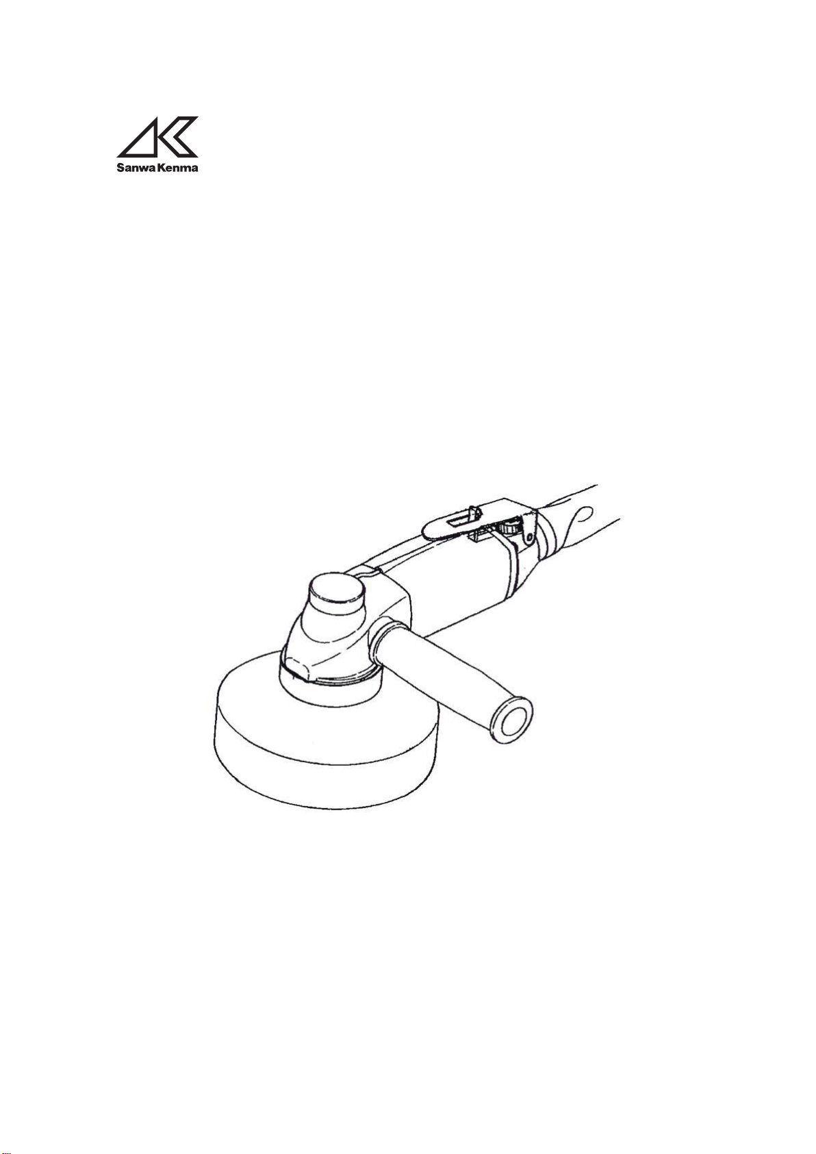
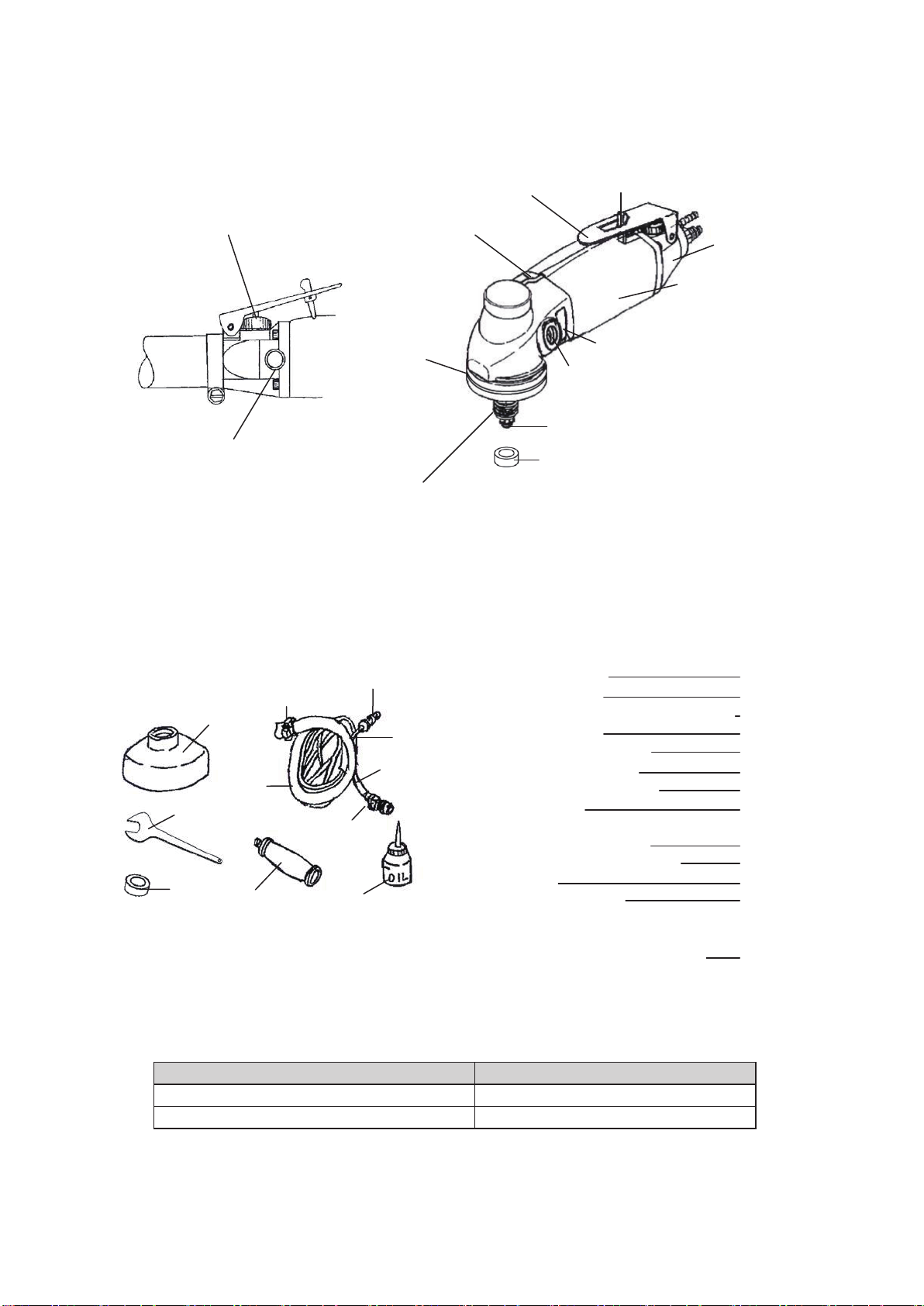
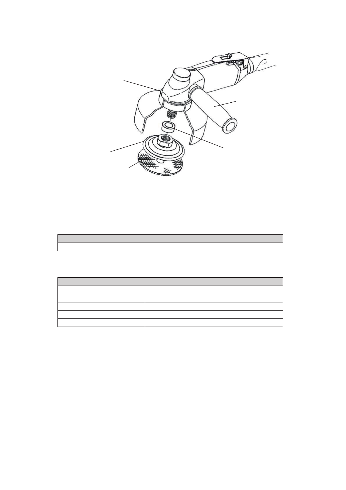
This polisher is equipped with rotating parts. During rotation of the polisher, the operator
shall hold the polisher by both hands; one hand grips the grip bar (see Figure 2, 3 and
4, page 6 and 7), another does the polisher body around the switch lever. In any cases
during rotating, anybody shall not touch the rotating parts of the polisher. Holding by one
hand is prohibited because another hand would have risk to touch the rotating parts.
When controlling airflow or water-flow, one hand shall hold the grip bar and another hand
would adjust the airflow control valve or the water-flow control valve under OFF condition.
WARNING
CAUTION
2. OPERATIONAL ENVIRONMENT
・ DO NOT ALLOW ANY OTHER OPERATORS TO ACCESS TO THE POLISEHR
Do not allow any other operators except specific operators to access to the work
place. Particularly be careful not to allow children to access the working area.
・ CAUTION AGAINST EXPLOSION AND FIRE
Do not use the polisher absolutely in potentially explosive atmospheres to prevent
explosion and fire.
・ KEEP A WORKPLACE IN ORDER
Keeping a worktable and peripheries disordered could cause a drop of the
polisher and the fraction is caught in the polisher. This is very hazardous. Be
careful to keep the workplace and its peripheries in order.
3. WORKING CLOTHING AND PROTECTIVE EQUIPMENT
・ WEAR APPROPRIATE PROTECTIVE EQUIPMENT
Operator engaged in polishing operation shall wear protective glasses, safety
shoes, rubber gloves and protective cap. At a dusty place, inhaling dust and
powder could cause respiratory diseases at throat and lungs. Therefore, when
polishing in such an environment, make sure to put a dust mask on. Furthermore,
when using the polisher, put a pair of earplugs on to prevent ear disease.
WARNING

4
CAUTION
・ WEAR PROPER PROTECTIVE CLOTHING
Do not wear a pair of knitted gloves and work clothing with lower-sleeve edge
opened. Wearing such gloves and loose clothing as well as long hair could be
drawn in or trapped of by the rotating parts of the polisher.
4. APPROPRIATE INSERTED TOOL
( TOOL INSERTED IN THE HAND-HELD POWER TOOL TO PERFORM POLISHING )
WARNING
・ DO NOT MOUNT ANY INSERTED TOOLS EXCEPT THE ONES FOR POLISHING
This polisher shall not be used for cutting. Solid inserted tools will cause injuries.
Do not mount any inserted tools to this polisher which are not intended for the
polishing operation such as grinding wheel, cutting-off wheel and dish wheel.
・ THE MAXIMUM SPEED OF THE INSERTED TOOL SHALL BE HIGHER THAN
THE RATED ROTATIONAL SPEED
The maximum speed of the inserted tool shall be higher than the rated rotational
speed marked on the nameplate of the polisher and described in
SPECIFICATIONS
in page 8.
・ MOUNT A FLEXIBLE POLISHING PAD DESIGNED FOR THIS POLISHER
This polisher is for polishing operation fitted with flexible polishing pad and various
soft materials or felt pad for polishing of surface like our DIA CERAMICA.
CAUTION
・ THIS POLISHER SHALL BE USED FOR WET-MODE OPERATION
Using dry-mode pad will cause extremely higher temperature and too much dust,
resulting in fire and respiratory diseases at throat and lungs.
5. OPERATOR’S KNOWLEDGE TO USE THIS POLISHER
CAUTION
・ DO NOT USE THE POLISHER UNTIL GETTING ADEQUATE KNOWLEDGE FOR
USE
Do not allow children or any other persons to operate the polisher, who do not
know how to operate or cannot operate properly.
6. POLISHING AT HIGH WORKPLACE
CAUTION
・ WHEN POLISHING AT HIGH WORKPLACE, ENSURE NOBODY IS UNDERNEATH
Dropping a work piece ( polishing material ) or the polisher itself could cause
accidents and injuries. When polishing at high workplace, the operator is
recommended to take fall-down measures such as safety belt.

5
7. ELECTRICAL INSULATING
WARNING
・ THE POLISHER IS NOT ISOLATED ELECTRICALLY
Contacting the polisher with electric supply would cause electrocution.
Comply with the current legislations and regulations relating to noise.
Plant or shop, which uses the polisher, must use the polisher with
the condition below the noise level regulated by the local administrative
authority, not to disturb neighbors. A sound shield is recommended to
use as necessary.
Attentive points :

6
NAME OF PARTS
STANDARD ACCESSORIES
Airflow Control Valve
Water-flow Control Valve
Switch Lock
Switch Lever
End Case
Polisher Body
W47mm X H44mm
Whole Length 200mm
Screw Hole for Grip Bar
( for left hand and right )
Name Plate
Water Pipe
Circumference
Groove
Water Spray Nozzle
Spindle M14 or M16 ( alternatively on request )
Spacer
Figure 1 Control Valve Figure 2 Name of Polisher
Figure 3 Standard Accessories
(1) Water-splash skirt
- Normal size 1pc
- Bigger size 1pc
(2) Hose fittings ( Hex Nipple G1/4 ) 1pc
(3) Air hose 7X10 1pc
(4) Couplers ( for water ) 1pc
(5) Flexible water hose 1pc
(6) Exhaust air duct hose 1pc
(7) Hose clamp 1pc
(8) Wrench
- 22mm for spindle 1pc
- 26mm for rubber pad 1pc
(9) Grip bar 1pc
(10) Motor oil 30mm31pc
( ISO-VG46 or DIN51502DL46 )
(11) Spacer for M14 or M16
depending on spindle size 1pc
(1)
(2)
(3)
(4)
(5)
(6)
(7)
(8)
(9) (10)
(11)
TABLE 1 DIMENSIONS OF WATER-SPLASH SKIRT
Diameter of Applicable Rubber Pad
80mm and 100mm
125mm
Water-splash Skirt
Normal Size with Inside Diameter 116mm
Bigger Size with Inside Diameter 136mm

7
OPTIONS
Clamping Mouth
on the Water-splash Skirt
Grip Bar
( included in STANDARD
ACCESSORIES.
See page 6 )
1. Rubber Pad
2. DIA CERAMICA
( Flexible Polishing Pad )
Spacer
( included in STANDARD
ACCESSORIES.
See page 6 )
Figure 4 Options
TABLE 2 RUBBER PAD
TABLE 3 FAMILY OF DIA CERAMICA
DIA CERAMICA ( FLEXIBLE POLISHING PAD )
V-series ( Vitrified bond )
M-series ( Metal bond )
R-series ( Resinoid bond )
BUFF-series
TSUYA-series
60V, 150V, 300V
60M, 150M, 300M
150R, 300R, 500R, 1000R, 2000R, 3000R
BUFF ( BLACK ), BUFF ( WHITE )
TSUYA ( BLACK ), TSUYA ( WHITE )
* Numbers represent mesh size ( grid size ) of grain contained in DIA CERAMICA respectively.
RUBBER PAD ( Nominal diameter in mm )
80, 100 and 125

8
・SPECIFICATIONS
Relation between speed and air pressure could be referred to the below Figure 5.
Figure 5 Relation of r/min and Compressed Air Pressure
APPLICATION
Polishing and rounding of curvatures and flat surfaces of marble, granite and terrazzo.
Relation of r/min and Compressed Air Pressure
( only reference )
Rated no-load speed at air pressure of 0.6MPa
Mass ( weight )
Maximum operating pressure of compressed air
Consumption of compressed air
3,890r/min (min-1)
1.2kg
0.6MPa
0.42m3/min at temperature 20℃ and
atmospheric pressure
r/min
5000
4000
3000
2000
1000
0
0.40 0.45 0.50 0.55 0.60 0.65 MPa

9
CHECK ITEMS BEFORE OPERATING
・ READ THE AIR PRESSURE ON THE GUAGE
Hold air pressure as specified before use. Operating the polisher at air pressure
more than the specified value could cause damage of the polisher and the flexible
polishing pad and, in the worst case, injuries to operator.
・ DO NOT USE POWER SOURCES OTHER THAN COMPRESSED AIR
Use of high-pressure gas ( e.g. oxygen, acetylene gas, propane gas etc. ) could
result in dangerous explosion. Do not use air other than compressed by air
compressor.
WARNING
・ DO NOT USE THE POLISHER FOR APPLICATIONS OTHER THAN SPECIFIED IN
THIS INSTRUCTION MANUAL
This polisher is exclusively for polishing stone materials. Do not apply it for
grinding and polishing of metal, wood, etc.
・ CARRY OUT VISUAL INSPECTION BEFORE OPERATING
Ensure each screw is not loose and the part are located as designated. In
addition, make sure that the wrenches and / or screwdriver is not left on the
polisher.
CAUTION
Ensure the following items before operating.
1. KEEP-IN-ORDER OF WORKPLACE
Keep the workplace in order before the start of polishing operation. When there is dust
around, it would be flown by the exhaust air conducted through the exhaust air duct
hose ( see Figure 3 and 6, page 6 and 11 ). Flying dust would cause respiratory
diseases at throat and lungs.
2. COMPRESSOR CAPACITY
Select and install a compressor with sufficient capacity margin for air consumption. Use
of the compressed air containing water and dust could cause rusting and other troubles.
Before operating, therefore, drain out water completely through the drain port provided at
the bottom of the compressor tank.
3. OPERATING AIR COMPRESSED PRESSURE
This polisher is designed for operation at the maximum air pressure of 0.6MPa. Since
the higher air pressure leads the higher rotational speed, do not apply the exceeded air
pressure against specified to prevent the bursting of the flexible polishing pad and / or
the rubber pad, which may cause injuries, and the short life of the motor of the polisher.

10
PREPARATIONS BEFORE OPERATING
WARNING
・ MAKE THE FOLLOWING PREPARATION BEFORE OPERATING
Complete items 1, 2.1, 3, 4 and 5.1 before connecting the air hose to the
compressor.
・ MAKE SURE THAT THE GRIP BAR IS SCREWED IN FIRMLY
Whenever the polisher is turned ON, i.e. in test for switch function ( item 7, page
13 ), test run ( item 9, page 13 ) and polishing operation ( HOW TO POLISH in
page 15 ), make sure that the grip bar is screwed in firmly.
1. MOUNT THE GRIP BAR
Firmly mount the grip bar ( see page Figure 2, 3 and 4, page 6 and 7 )
2. THE PROCEDURE TO MOUNT AND DEMOUNT THE WATER-SPLASH SKIRT
2.1 MOUNTING OF THE WATER-SPLASH SKIRT
Attentive point : The purpose of water-splash skirt is only to decrease water
splash from the water spray nozzle. As this water-splash skirt
is elastic and not strong enough, this does not work as a guard.
(1) Select a proper size of water-splash skirt according to TABLE 1 in page 6
(2) Install the water-splash skirt on the polisher body while expanding the
clamping mouth ( see Figure 4, page 7 ) of water-splash guard from inside
with fingers so that the clamping mouth fits onto the circumference groove
( see Figure 2, page 6 ) on the polisher body
3. PREPARE THE POLISHER
CAUTION
・ CHECK FOREIGN PARTICLES
Foreign particles in the motor could cause rotating failure of the motor. Therefore,
when connecting the air hose to the compressor, be careful not to let any dust,
small stone, etc, into the motor.
Securely fit the flexible water hose, the air hose and the exhaust air duct hose.
Failure to follow this instruction causes the disconnection and whipping of the
horses and finally injuries.
・ BE CAREFUL NOT TO DAMAGE THE AIR HOSE AND THE WATER HOSE
The polisher body, the air hose and the water hose are disconnected when shipping.
Connect these together as illustrated in Figure 6 in page 11.
2.2 DEMOUNTING OF THE WATER-SPLASH SKIRT
(1) Demount the flexible polishing pad and the spacer
(2) Pull out the water-splash skirt by hand

11
Procedures:
(1) Connect the water hose. For this procedure, warm up the joint part of the flexible
water hose in hot water to facilitate the joint work.
(2) Guide the hose joint ( female ) through the air hose in advance and tighten it.
The required tightening torque is approximately 15 N m ( 1.53kg m ).
After tightening, ensure that the air hose is not disconnected even if adding
tension load thereto.
(3) Insert the exhaust air duct hose in the end case and clamp it with the hose clamp.
Figure 6 Connections of Hoses
4. TAKE NECESSARY MEASURES
In terms of environment, health and safety codes, take the necessary measures properly
when operating the polisher, referring to DECLARATION in page 1.
Exhaust Duct
( Upper )
Hose Nipple
End Case
Hose Joint
( Male )
Air Hose
Flexible Water Hose
Exhaust Air Duct Hose
Hose Clamp
Hose Joint
( Female )

12
5. MOUNTING AND DEMOUNTING PROCEDURES FOR THE RUBBER PAD AND THE
FLEXIBLE POLISHING PAD
5.1 MOUNTING OF THE RUBBER PAD AND THE FLEXIBLE POLISHING PAD
(1) Select a combination of rubber pad and flexible polishing pad, referring to
TABLE 2 and 3 in page 7
(2) Mount the water-splash skirt in accordance with 2.1 MOUNTING OF
WATER-SPLASH SKIRT
(3) Fold back the water-splash skirt
(4) Place the spacer through the spindle by hand
(5) Screw in the rubber pad onto the spindle by hand
(6) Tighten the screw using two wrenches.
The required tightening torque is approximately 15 N m ( 1.53kg m ).
(7) Restore the water-splash skirt to the original shape
(8) Put the flexible polishing pad onto the rubber pad
5.2 DEMOUNTING OF THE RUBBER PAD AND THE FLEXIBLE POLISHING PAD
(1) Peel off the exhausted flexible polishing pad from the rubber pad
(2) Loose the rubber pads using two wrenches
(3) The required loosening torque is approximately 15 N m ( 1.53kg m )
(4) Screw out the rubber pad by hand while paying attention not to lose the
spacer
(5) For replacing, follow the procedure of 5.1 MOUNTING OF RUBBER PAD AND
FLEXIBLE POLISHING PAD
6. CONNECT THE AIR HOSE TO THE COMPRESSOR
(1) Make sure to clean out the fitting part ( see Figure 3, page 6 ) to remove
dust and foreign particles so that dust and / or any foreign particles do not
contaminate inside of hoses. Contamination possibly damages the air motor.
(2) Securely connect the air hose to the compressor, ensuring that the hose is
damage-free and tightly jointed. The required tightening torque would be in
general 15 N m ( 1.53kg m ).
WARNING
・ BEFORE MOUTING OR DEMOUNTING THE RUBBER PAD AND THE FLEXIBLE
POLISHING PAD, TURN OFF THE POLISHER
Before mounting or demounting the rubber pad and the flexible polishing pad,
turn OFF the polisher using the switch lever without fail to prevent incidental
accidents. In addition, disconnect the air hose from the compressor.
・ PREVENT INCIDENTAL STARTING
When mounting or demounting the rubber pad and the flexible polishing pad
on / from the polisher, disconnect the air hose from the compressor. Careless
turning ON of the switch lever with the air hose connected could result in injuries.

13
7. TEST FOR SWITCH FUNCTION
(1) Make sure that the grip bar is screwed in firmly on the polisher body.
(2) Adjust the pressure of the compressor at 0.4MPa. Higher pressure makes higher
speed of polisher, which is not recommendable for this function test.
(3) Hold the grip bar ( see Figure 4, page 7 ) by one hand while pushing the switch
lock by a finger of another hand. Then, push the switch lever down to turn ON.
Release the finger from the switch lever to turn OFF while holding the grip bar
and the end case by the hands. The polisher is stopped automatically and
immediately. In addition, the switch lever is locked by the switch lock automatically
( see Figure 8, page 16 ).
8. TURNING OFF THE POLISHER
Before connecting the air hose to the compressor, ensure that the polisher is locked
at OFF position. Or, it would cause sudden start of the polisher. This is very
hazardous. When putting the polisher on floor or worktable, make sure to turn the
switch lever to OFF position ( see Figure 8, page 16 ).
9. TEST RUN
WARNING
・ CONNECT THE AIR HOSE SECURELY
Disconnection of the air hose during operation could result in hazardous whipping
of the air hose. Connect the air hose securely. In addition, when connecting the
air hose to the compressor, ensure the switch lever is locked at OFF position.
・ DO NOT TOUCH THE ROTATING PARTS
Do not access to the flexible polishing pad and the rotating parts while the
polisher is in running.
・ MAKE TEST RUN BEFORE POLISHING
When the polisher has reached the rotations for use after start, ensure no
inordinate noise and / or vibration. For the test run time, refer to TEST RUN TIME
in page 14. Polishing without test run could cause injuries.
・ FOLLOW THE RECOMMENDED SPEED OF POLISHER FOR THE TEST RUN
The recommended speed of polisher for the test run shall be smaller than the
maximum operating speed of flexible polishing pad, specified by its manufacturer.
・ DO NOT CARRY OUT TEST RUN OPERATION IN IMPROPER PLACE
Test run in improper place is hazardous. Secure stable scaffolding and hold the
operator’s body in stable position all the times.
・ STOP THE POLISHER IMMEDIATELY IN CASE OF UNINTENDED REACTION
SHOWN
Stop the polisher immediately if something inordinate condition is found during run.

14
CAUTION
・ NO CONTACT WITH ROTAING PARTS DURING TEST RUN
When switching ON, ensure that the flexible polishing pad is not in contact with a
work piece and any substances. Such contacts could cause injuries.
・ DURING TEST RUN, ANY OTHER PEOPLE SHALL KEEP AWAY
Only limited person, however, who is allowed to access to the test run area by
management, would be possible to access the test run area.
・ BE CAREFUL NOT TO DAMAGE THE AIR HOSE AND THE WATER HOSE
(1) Referring to Figure 5 in page 8, adjust the pressure of compressed air so that it
rotates at the speed specified by the manufacturer of flexible polishing pad.
(2) Close the airflow control valve fully and open again slightly.
(3) Turn ON the switch lever
(4) Adjust the airflow control valve slowly until it opens completely little by little
(5) With this condition, make test run for the specified period of test run time described
below in this page.
Continuing the test run and / or polishing operation with the damaged flexible polishing
pad will be very hazardous. Before starting test run, ensure that any other person is
not around and the polisher is in proper condition while test run.
TEST RUN TIME :
Whenever flexible polishing pad is replaced more than 3 minutes
Whenever daily polishing operation is started more than 1 minute

15
・HOW TO POLISH
WARNING
・ TURN OFF THE SWITCH LEVER
Whenever interrupting the polishing operation and replacing the flexible polishing
pad, and after finishing the operation, turn OFF the switch lever and disconnect
the air hose from the compressor.
・ USE A PAIR OF PROTECTIVE GLASSES DURING POLISHING OPERATION
Inordinate impact to the polisher or the flexible polishing pad could result in tear
and / or crack of the pad. Handle them with good care. In case the polisher body
is dropped or hit against other substances, make sure to inspect that the flexible
polishing pad is crack-free and the polisher body is damage-free. If they are
cracked or damaged, stop using the polisher.
・ CONNECT THE AIR HOSE SECURELY
Disconnection of the air hose during operation could result in hazardous whipping
of the air hose. Connect the air hose securely. In addition, when connecting the
air hose to the compressor, ensure the switch lever is locked at OFF position.
・ DO NOT TOUCH THE ROTATING PARTS
Do not access to the flexible polishing pad and the rotating parts while the
polisher is in running.
・ MAKE TEST RUN BEFORE POLISHING
When the polisher has reached the rotations for use after start, ensure no
inordinate noise and / or vibration. For the test run time, refer to TEST RUN TIME
in page 14. Polishing without test run could cause injuries.
・ FIX FIRMLY THE WORK PIECE USING CLMAP AND / OR EQUIVALENTS
Failure to be fixed could cause an incidental drop of the work piece, in the worst
case, injuries.
・ DO NOT CARRY OUT POLISHING OPERATION IN IMPROPER PLACE
Polishing in improper place is hazardous. Secure stable scaffolding and hold the
operator’s body in stable position all the times.
・ DO NOT POLISH EXCEPT SPECIFIED OPERATING CONDITIONS
Do not operate the polisher exceeding the rated rotational speed and maximum
operating pressure of compressed air indicated on the nameplate and in the
instruction manual. Failure to do so could cause damage of the polisher and
flexible polishing pad, in the worst case, injuries.
・ STOP THE POLISHER IMMEDIATELY IN CASE OF UNINTENDED REACTION
SHOWN
Stop the polisher immediately if something inordinate condition is found during run.
・ PAY SPECIAL ATTENTION DURING POLISHING OPERATION
Do not use the polisher when operator feels fatigue or find an adverse effect of
medicine or alcohol.

16
CAUTION
・ DO NOT DAMAGE THE FLEXIBLE POLISHING PAD AND THE POLISHER
Careless drop or hit of the polisher against other substances could cause damage,
cracking and deformation of the flexible polishing pad and the polisher. In such a
case, ensure that it is free from such defects before operating. Failure to follow
this caution could cause injuries.
・ PAY ATTENTION TO EXHAUSTING DIRECTION
Exhausted air might contain motor oil, which could cause accidents and / or oil
disease. Take good care not to directly expose the eyes and ears to the
exhausted air.
・ BE CAREFUL NOT TO DAMAGE THE AIR HOSE AND THE FLEXIBLE WATER
HOSE
・ MAKE SURE THAT THE FLEXIBLE WATER HOSE IS CONNECTED TIGHTLY
Failure to do so would possibly result in dry-mode operation due to luck of water,
causing fire and respiratory diseases at throat and lungs.
1. CONNECTION FOR WATER SUPPLY
Connect the flexible water hose to the hose nipple on the polisher body ( see Figure 6,
page 11 ) and to the water source. Adjust the water flow rate by the water-flow control
valve so that the work piece and the flexible polishing pad is cooled enough and that
polishing effect is optimized.
Close
Water-flow Control Valve
Open
Figure 7 Water-flow Control Valve
2. SWITCH OPERATIONS
ON position for polishing Grip the polisher body with the switch lock while
pushing it frontward together with the switch lever
OFF position to stop polishing Grip off the switch lever
Switch Lever
OFF
ON
Airflow Control Valve
Polisher Body End Case
Figure 8 Switch Operations
Switch Lock
- Push frontward release
- Free lock

17
Adjust airflow rate by turning the airflow control valve in the range MIN position to
MAX position shown in Figure 9. Turning it over MAX position to STOP position
reduces the airflow rate due to valve structure.
3. HOW TO POLISH A WORK PIECE WITH THE FLEXIBLE POLISHING PAD
When the polisher rotation gets stable after the start, begin the polishing operation, Put
the flexible polishing pad slowly on the face to be polished when it comes in touch with
a work piece. Too much force to the pad would damage the work piece and cause
quick worn-out of the pad, and would not be an efficient polishing.
The efficient polishing depends on many elements, characteristics of work piece, the
flexible polishing pad, pressure between the flexible polishing pad and work piece, water
flow rate, skill of operator and polisher speed.
The operator would have an experience of optimum water flow rate. Contact of polisher
speed is utilized by airflow control value ( see Figure 1, page 6 ) The optimum polishing
speed, therefore, could not be specified in this instruction manual due to too many
elements.
Relation of r/min and compressed air pressure is shown in Figure 5 in page 8. The
operator would have an experience of optimum polisher speed.
4. CAUTIONS IMMEDIATELY AFTER USE
After the polishing operation, turn OFF the switch lever and place the polisher on floor
ensuring that its rotation is completely stopped. Failure to do so could cause accidents.
Inordinate impact to the polisher body could result in tear or crack of the polisher and
the flexible polishing pad. Handle them with good care.
Switch Lever
Stop
Max.
Min.
Airflow Control Valve
Figure 9 Airflow Control Valve

18
・ USE DESIGNATED PARTS IN THIS INSTRUCTION MANUAL
Use only the parts shown in this instruction manual when accessories are
replaced.
WARNING
・ EXECUTE AN ADEQUATE MAINTENANCE
Remove dust from the polisher and keep it clean. Particularly take good care to
protect the connections with the compressor and polisher from contamination of oil
except ISO-VG46 or DIN51502DL46, water and dust.
・ HANDLE THE AIR HOSE WITH GOOD CARE
Do not carry the polisher with its air hoses, flexible water hose and exhaust air
duct in hand and do not add any tension to these hoses and duct. Doing so
would cause damage of these hoses and duct. Furthermore, be away from heat,
oil and article with sharp edge.
CAUTION
・AFTER USE
1. DISCONNECT THE AIR HOSE
(1) Close the stop-valve on the compressor
(2) Turn OFF the polisher by switch lever
(3) Disconnect the air hose and exhaust air duct hose
(4) Disconnect the flexible water hose from water source
The flexible water hose does not need to be disconnected from the polisher body
2. EXECUTE AN ADEQUATE MAINTENANCE
Execute an adequate maintenance, referring MAINTENANCE AND CHECK in page 19
3. STORE THE POLISHER AT SAFE, CLEAN AND DRY PLACE
After cleaning out dust and mist from the polisher, store it at safe, clean and dry
place.
Furthermore, do not store it at the following places;
- where children reach or take it easily
- where temperature and humidity fluctuate rapidly
- where the polisher is exposed to rain or high humidity
- where the polisher is exposed to direct sun ray
Table of contents