Equipment Supplied/
Description of the Functions
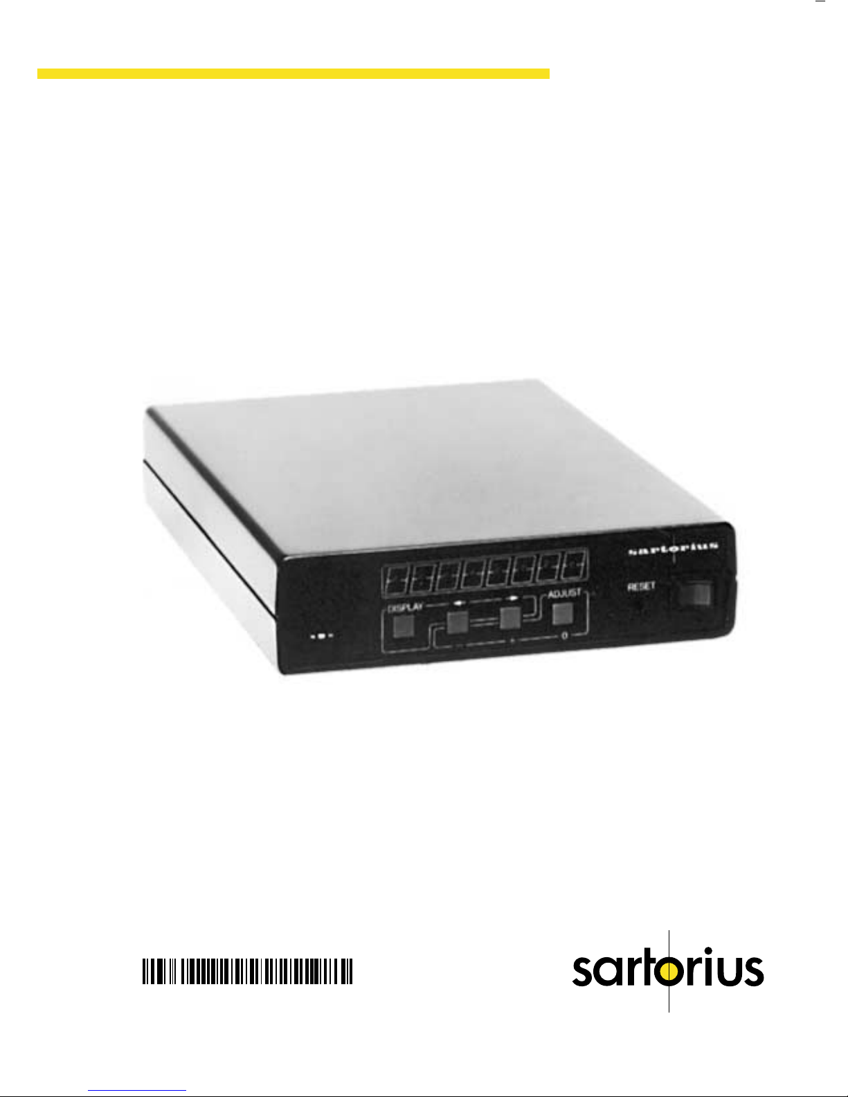
Equipment Supplied
– Converter YDA 01 Z
– Power cord
– Standard cable “MP8” for connecting MP7, MP7-2
or MP8 balances/scales to YDA 01 Z
– V 24 cable for connecting MC1 balances/scales
to YDA 01 Z
Description of the Functions
Digital/analog converter YDA 01 Z is designed to
convert digital signals into analog voltages or loop
currents. Such an analog signal is available with two
different voltages and three different loop currents
at a 5-in round socket (similar to a DIN stereo jack).
The lower rating of the two voltages ranges from
+1 volt to –1 V.
The higher voltage ranges from +10 V to –10 volts.
The current interface can be adjusted to the following
loop currents:
a) 4–20 mA
b) 0–10 mA
c) 0–20 mA
Setting a) complies with ISA S50.1, Standard
Class U, with the following specifications:
Load resistance: 300–800 Ω
Supply voltage: 23–30 V
Internal resistance: 600 Ω
Intrinsic safety: 250 Ω
6