Schneider Kreuznach PC-SUPER-ANGULON 28 mm f/2.8 User manual

Schneider Optics Inc
285 Oser Avenue
Hauppauge · NY ¡¡788 · USA
Phone 63¡76¡5000
Fax 63¡76¡5090
info@schneideropticscom
wwwschneideropticscom
Exclusive distributor for the USA
PC-SUPER-ANGULON
28mmf/2.8
UserManual

2ListofContents
Name of Parts and Cross Section of the Lens 3
General Description 4
Perspective Correction for Analog and Digital Photos 6
Large Image Circle for Lens Shifts up to ¡¡ mm 8
Fixing and Removing the Lens ¡0
Replacing the Mount for a Different Camera ¡0
Parallel Shift ¡1
Focusing and Depth of Field ¡2
Measuring the Exposure ¡3
Filters, Lens Hood and Camera Mounts ¡4
Specications ¡6
Shape, appearance and specications are subject to change without notice

3
1
0,7
0,5
0,4
0,35
0,3
5
3
2
1,5
1,25
1
8
5,6
4
2,8
4
8
16
22
P
C
-
S
U
P
E
R
-
A
N
G
U
L
O
N
NameofPartsandCrossSectionoftheLens
Focusing ring
Distance scale
Depth of eld scale
Aperture scale
Aperture setting ring
Pre-set aperture setting lever
Shifting knob
Index
Knurled ring
Camera mount
Fixing screw for camera mount

8
3
1
0,7
0,5
0,4
0,35
m
oo
5,6
114 16
2,8 22
22
4
8
4
8
16 16
22
53
2
1,5
1,25
8
3
1
0,7
0,5
0,4
0,35
m
oo
5,6
114 16
2,8 22
22
4
8
4
816 16
22
53
2
1,5
1,25
GeneralDescription
Not shifted
Maximally shifted
The SCHNEIDER PC-SUPER-ANGULON 28 mm f/28 is a very high-quality
wide-angle lens for 35 mm analog and digital SLR cameras and provides a
parallel shift facility like the sliding lens panel of professional large-format
cameras for correcting converging vertical lines and for manipulating the
perspective especially for use in architectural and product photography
Whereas normal 35 mm lenses have an image circle diameter of around
44 mm so that all four corners of the image are inside the image circle, the
PC-SUPER-ANGULON 28 mm f/28 provides an incredible 62 mm image
circle Decentration up to ¡1 mm is possible within this area using a dove-
tail guide which can be adjusted easily and exactly The rotatable mount
allows any desired shift direction

GeneralDescription
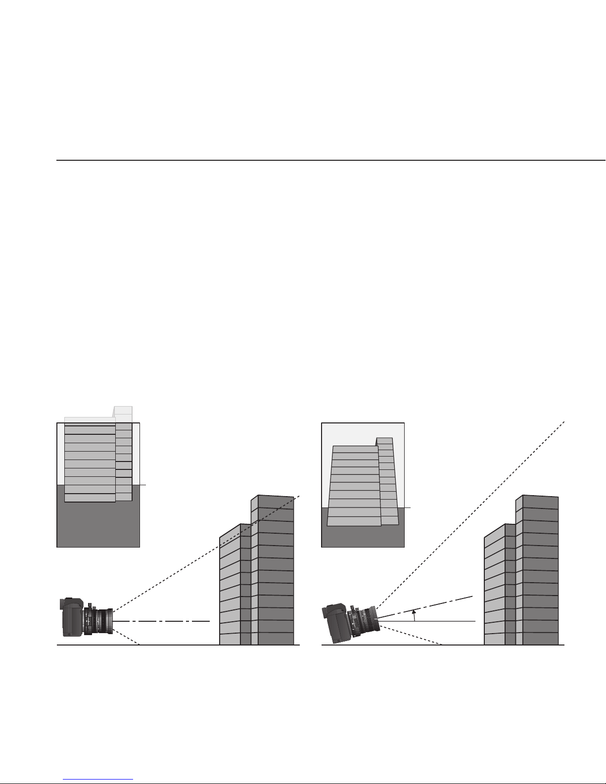
Vertical shift is the most popular: upward, especially when photographing
high buildings, so that the camera does not have to be tilted upward; and
downward for product shots at an oblique angle or also for shots from
high locations such as towers or mountains so that the camera does not
have to be tilted downward When the camera is tilted either upward or
downward, perpendicular lines are not imaged as perpendicular, but rather
converge upward or downward, which is very pronounced in wide-angle
shorts and can be very irritating
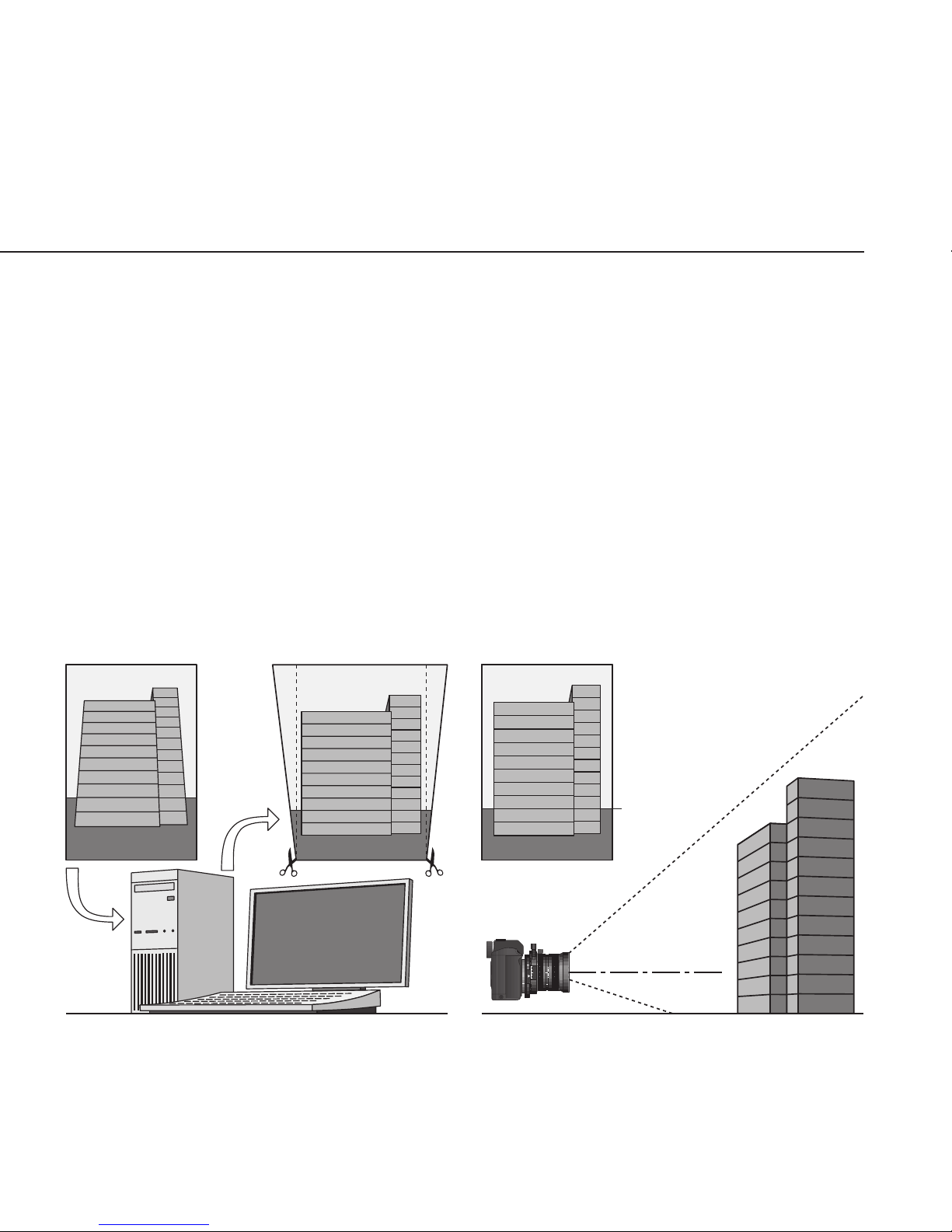
These converging lines can be prevented with the PC-SUPER-ANGULON
28 mm f/28 just as with adjustable large-format cameras If the adjustment
range of ¡1 mm (the clearance of the camera bayonet xes this limit) is not
sufcient in extreme cases due to the oblique view being too steep, the
parallel shift of the lens largely prevents the sloped position of the con-
verging lines and furthermore also reduces the vertical compression of the
imaged object which would otherwise occur The image then again corre-
sponds to the natural visual impression
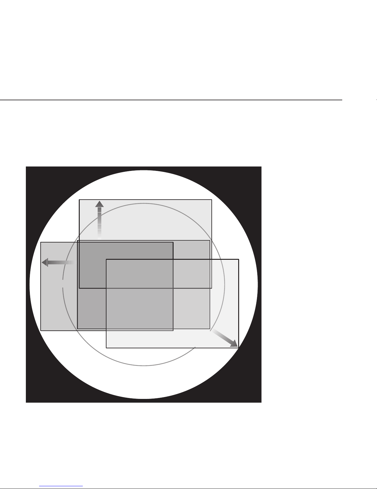
The rotary mount, however, also allows horizontal movements or a shift in
a slanted direction, e g to be able to take a frontal photograph without any
distortion from a lateral location or a location with a slanted offset if this
would otherwise be impossible due to an obstacle or potential reections

6PerspectiveCorrectionforAnalogandDigitalPhotography
8
3
1
0,7
0,5
0,4
0,35
m
oo
5,6
114 16
2,8 22
22
4
8
4
816 16
22
53
2
1,5
1,25
Horizon
Too much
foreground
Optical axis
Building is true to scale
but cropped on top
8
3
1
0,7
0,5
0,4
0,35
m
o
o
5,6
11
416
2,822
22
4
8
4
8
16 16
22
5
3
2
1
,5
1
,25
Horizon
Optical axis
Building not true to scale,
vertically compressed
Converging lines
≈ ¡3°
The equalizing of converging lines or of unfavorable perspective due to a
camera location made necessary by obstacles, reections or danger, eg
trafc, is not only interesting for conventional analog photography, but also
for digital photography when higher quality demands are made While digi-
tal images or digitized (scanned) analog images can be equalized on the
computer using image editing software such as Photoshop, this is, however,
associated with substantial degrading: If the rectangular image is distorted
in the manner of a trapezoid for the parallel alignment of the converging
lines, the interpolation (recalculation of the pixels) required for this reduc-

PerspectiveCorrectionforAnalogandDigitalPhotography
Too
low
Too
wide
8
3
1
0,7
0,5
0,4
0,35
m
oo
5,6
114 16
2,8 22
22
4
8
4
816 16
22
53
2
1,5
1,25
Horizon
Optical axis
Building is true to scale and
completely reproduced
Vertical lines
are parallel
Vertical shift
of 7 mm
es the sharpness, produces just visible bluish violet or reddish brown color
fringes at edges which have been made perpendicular under fairly high en-
largement and gives an image with incorrect proportions (width-to-height
ratio) Since the nal image must, however, be rectangular, the triangular ar-
eas projecting on two sides have to be cut off, which shows how many pix-
els, which are important for high resolution, are lost At the same time, the
surroundings almost always become very small at the narrow side of the
trapezoid or the actual motif is even cropped The optical equalization ac-
tually during the shot with the PC-SUPER-Angulon 28 mm f/28 avoids this

8LargeImageCircleforLensShiftsupto1¡mm
The PC-SUPER-ANGULON 28 mm f/28 already produces an exceptionally
attened image at full aperture within the 62 mm image circle which is thus
twice as large in area relative to the image circles of other 35 mm lenses
Sharpness and contrast are increased further in the central area used with-
out shift by stepping down slightly to f/4 to f/56 Sharpness, contrast and
brightness naturally drop outside this area due to the huge image angle
with an open aperture The full aperture with a decentered lens is there-
fore only intended for the image composition and the focusing A good im-
aging performance is obtained at the edge when stepping down further in
dependence on the adjustment path; an aperture of ¡1 is recommended at
maximum shift Distortion and vignetting are exceptionally low
While the image quality falls considerably in the close range with many
wide-angle lenses, the good imaging properties of this lens are maintained
thanks to “oating elements” (a distance-coupled axial shift of a lens ele-
ment group relative to the remaining system) This makes this lens very in-
teresting e g for model shots
The adjustment takes place at a shifting knob on a exible shaft which is
easy to grip and sensitive in operation Millimeter scales on mutually oppo-
site sides allow comfortable reading in any shifting knob position Since the
shift is possible at both sides of the zero position, the most favorable ori-

LargeImageCircleforLensShiftsupto1¡mm
Natural size
max. ¡¡ mm
max.
¡0.5 mm
max.
9.5 mm
I
m
a
g
e
c
i
r
c
l
e
4
4
m
m
I
m
a
g
e
c
i
r
c
l
e
6
2
m
m
entation can always be chosen, e g irrespective of the shift direction with
the knob at the bottom with free hands, or rather at the top at the tripod
With a shift to
the left or to the
right, the shifting
knob can always
be at the left so
that the right
hand can hold
the camera and
remain on the
release button
With a diagonal
shift, the adjust-
ment path
should not go
beyond the lock
noticeable at
95 mm to pre-
vent vignetting

¡0 FixingandRemovingtheLens
The lens is available in a connection socket to match different 35 mm SLR
camera systems and is inserted into the camera bayonet or thread for fas-
tening to the camera such that the red dot on the connection socket is op-
posite the corresponding marking on the camera
To lock the lens in the bayonet or thread and to release it again, the lens
should be rotated at the knurled ring and not at the tube since the latter is
not rigidly connected to the bayonet or thread due to the rotary mount
and since there is therefore a risk that the tube will turn without the bayo-
net or thread engaging and tightening up to the stop
The camera mount of the lens is fastened using Phillips screws and can be
replaced to match the new camera on a change of the camera system The
user can make the retting him or herself using a size zero Phillips screw-
driver The table on page ¡5 shows the camera systems for which camera
mounts can be obtained and gives their order numbers
ReplacingtheMountforaDifferentCamera

¡1ParallelShift
The lens is shifted perpendicular to the optical axis relative to the bayonet
mount and so also relative to the taking format by rotating a knurled shift-
ing knob at a shaft which is elastically exible to protect against its damage
or injury to the user The lens tube can be rotated continuously to the left
or the right in a rotary mount so that the parallel shift can be made in any
desired direction It is best to grip the lens at the attened part with the
millimeter scales for this purpose 45° latch steps ensure a precise vertical
or horizontal parallel shift as required
The maximum path of ¡1 mm at both sides can be utilized to the full in the
shift direction of the short image edge (vertical in landscape format and
horizontal in portrait format) if the camera is stopped down to at least f/8
On a shift in the direction of the long image edge (horizontally in landscape
and perpendicular in portrait), low vignetting of the image corners oppo-
site to the shift (= of objects on the same side of the shift because of the
upside-down image) may occur over the last half millimeter It is therefore
recommended only to utilize the shift path up to 105 mm here and to stop
down to f/¡1 with more than 9 mm to avoid this vignetting in critical motifs
The noticeable latch step at 95 mm should not be exceeded diagonally
even at f/¡1 with parallel shifts since then the image corner decentered the
most will contact the image circle edge (see image on page 9)

¡2 FocusingandDepthofField
The focusing of wide-angle lenses appears to be relatively non-critical due
to their large depth of eld However, careful focusing is actually necessary
to utilize the high imaging quality of this lens to the full To ensure maxi-
mum brightness of the focusing screen and the best recognition of the ide-
al focusing point, the aperture should be opened by pivoting the stopping-
down lever toward the shifting knob The aperture setting ring therefore
remains on the set working aperture so that the aperture can later again
be closed to the working aperture quickly using the stopping-down lever
directly before the shot without moving the eye from the viewnder
Focusing can generally take place before or after the parallel shift as de-
sired However, if the LED focus display of an autofocus camera is used for
manually focusing, focusing must take place in the centered position (i e
with a non-shifted lens) because the AF sensor requires incidence of light
approximately parallel to the axis, but the light is obliquely incident on the
sensor when the lens is shifted The parallel shift which then takes place
after the focusing does not inuence the set distance
The f-numbers at both sides of the index mark for distance and aperture
indicate the depth of eld: If e g everything from ¡ m to 3 m should be
sharp, the distance ring should be set so that the meter gures ¡ and 3 are
above the same f-number (here: 8) at both sides of the index mark

¡
If the measurement is not carried out using a separate hand exposure me-
ter, but using the TTL exposure meter integrated in the camera, it is neces-
sary to measureinthecenteredposition of the parallel shift while stop-
ping down to the workingaperture because the arrangement and align-
ment of the measuring cell of almost all SLR cameras requires a direction
of light incidence axially symmetrically to the lens bayonet With an oblique
incidence through the lens displaced from the center, some of the light
bundle can be shadowed so that then less light is incident onto the mea-
suring cell A higher exposure would therefore be displayed or set with an
automatic exposure system so that overexposure would result
If the exposure is measured with a non-shifted lens, the camera must
equally be aligned with the motif as if the motif would later also thus be
photographed with a non-shifted lens
The darkening of the image visible in the viewnder with a lens shifted a
large distance does not carry over to the image and so also does not re-
quire any correction of the exposure This is due to a larger light fall-off at
the open aperture and due to the viewnder system being aligned to an
exactly centered lens and not being adjustable to the shifted lens as well as
to the mirror not going down far enough for the low position of the lens in
the event of a downward shift No vignetting occurs at the actual taking
MeasuringtheExposure

¡ Filters,LensHoodandCameraMounts
Only the oversized B+W WA lters of the size 67 EW can be used with
the SCHNEIDER PC-SUPER-ANGULON 28 mm f/28 due to the extreme-
ly large image angle utilized at maximum shift up to 934° The following
table shows the order numbers of the most popular lter types – further
types are available The two B+W polarization lters shown there (linear
and circular) have a special rotary mount and are dimensioned such that
they do not produce vignetting even at maximum parallel shift of the lens
An additional lens hood can, however, unfortunately not be used in combi-
nation with these polarization lters
Furthermore, a special lens hood with a lter mount is also available which
does not produce vignetting at maximum shift The lter plates of 74 mm
diameter which can be inserted there are held in this specal lens hood by
an adapter ring belonging to the lens hood
The following table also shows the order numbers of the camera mounts
with which the lens can be tted to match the new camera bayonet or
thread if the camera system is changed
The PC-SUPER-ANGULON 28 mm f/28 with Leica R bayonet mount is
only available through the camera manufacturer’s distribution channel

¡Filters,LensHoodandCameraMounts
Wide-angleltersofsize6EW Orderno.
B+W UV Filter with MRC coating 40295
B+W Skylight lter MRC coating 14386
B+W Käsemann linear polarizing lter 75246
B+W Käsemann circular polarizing lter with MRC coating 16518
More Filters of size 67 EW on request
Speciallenshoodwithlterholder 60013
B+W UV inlay lter 74 mm with MRC coating 45366
B+W Skylight inlay lter 74 mm with MRC coating 46585
Cameramounts
Canon EOS 45733
Canon FD 19106
Contax/Yashica 19118
Leica R Lens available only through Leica
M42 thread 19119
Minolta AF/Sony a 19124
Minolta MD 19105
Nikon AI 19104
Olympus OM 19120
Pentax K/Samsung GX 19098

¡6 Specications
Relative aperture ¡:28
Effective focal length 292 mm
Nodal point separation HH' 579 mm
Optical design ¡2 lenses in ¡0 groups
Near distance correction Floating elements
Image circle diameter 62 mm
Image angle 934°
Format 24x36 mm
Format diagonal 432 mm
Max displacements in landscape format 1¡ mm vertic, ¡05 mm horiz
in portrait format ¡05 mm vertic, 1¡ mm horiz
in both formats 95 mm diagonal
Aperture settings 28 to 22 in half stop increm
Setting of preset working aperture With stop-down lever
Nearest distance 028 m
Smallest full-format object size 2¡9x¡46 mm, scale appr ¡:6
Filter thread 67 EW (B+W Filter)
Total length (depending on camera mount) appr 89 mm
Max diameter 75 mm + 22 mm shifting knob
Weight (depending on camera mount) appr 565 g
Order number (without camera mount) 39789
Table of contents