Shimadzu CTO-40C CL User manual

228-97203A
Jun. 2022
Column Oven
For Shimadzu Liquid Chromatograph
CTO-40C CL
Instruction Manual
Read this manual thoroughly before you use the product.
Keep this manual for future reference.

This page is intentionally left blank.

Read this Instruction Manual thoroughly before using
the product.
Thank you for purchasing this product.
This instruction manual describes the basic operation, and accessories and options for this
product. Read this manual thoroughly before using the product and operate the product
in accordance with the instructions in this manual.
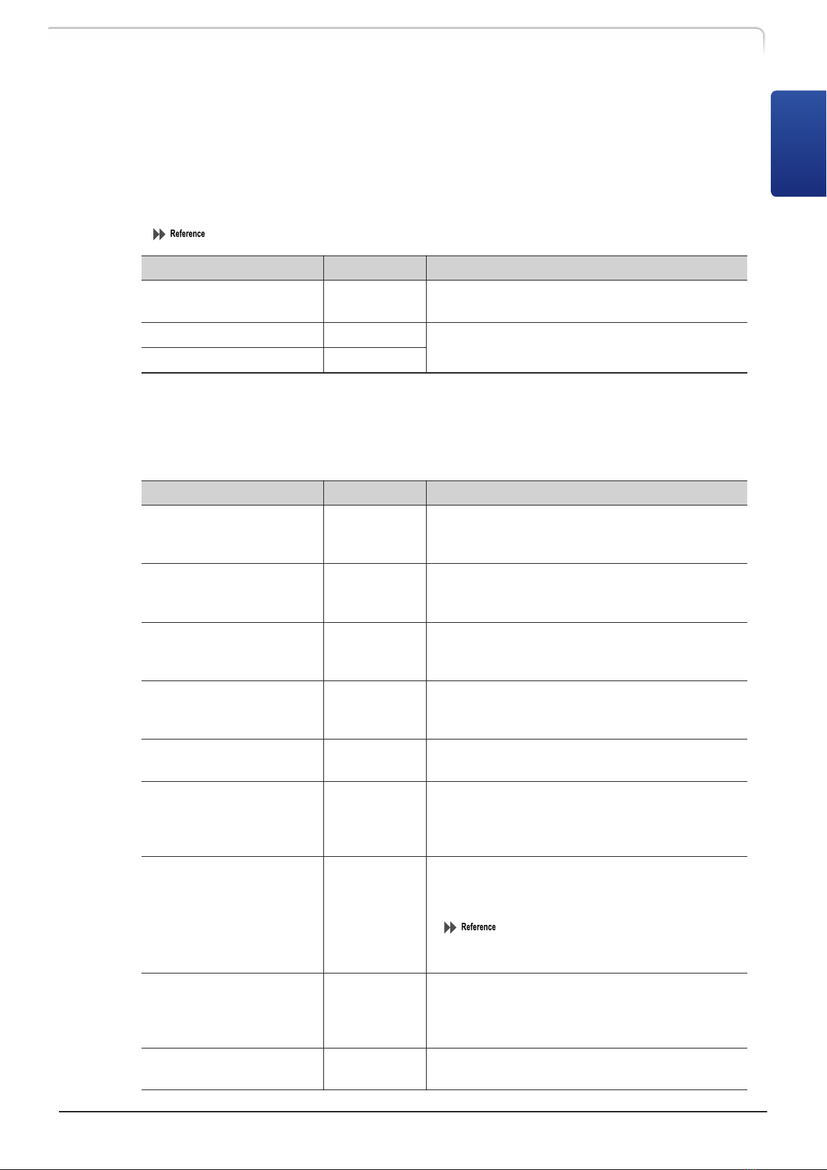
The following instruction manuals are included with the product.
Document Name Document
No. Description
Instruction Manual (PDF) 228-97203 This instruction manual.
System Guide (PDF) 228-97194
This manual provides details on how to use
the system:
system performance optimization, analysis
procedure, troubleshooting, validation,
installation, etc.
Safety Guideline
(Booklet/PDF) 228-97195 This manual describes the precaution
instructions to ensure safe operation.
Read "Safety Guideline" thoroughly before using the product.
"Safety Guideline" describes the information about the warranty, after-sales service,
safety instructions and precautions to ensure safe operation of the instrument.
Keep this manual for future reference.
IMPORTANT
• If the user or usage location changes, ensure that the manual is always kept
together with the product.
•If any manual or a product warning label is lost or damaged, immediately contact
your Shimadzu representative to request a replacement.
•To ensure safe operation, read the accompanying booklet "Safety Guideline"
before using the product.
•To ensure safe operation, contact your Shimadzu representative if product
installation, adjustment, re-installation (after the product is moved), or repair is
required.
ã 2019-2022 Shimadzu Corporation. All rights reserved.
Original version is approved in English.
Introduction
CTO-40C CL i
Notice
• Information in this manual is subject to change without notice and does not represent
a commitment on the part of the vendor.
• Any errors or omissions which may have occurred in this manual despite the utmost
care taken in its production will be corrected as soon as possible, although not
necessarily immediately after detection.
• All rights are reserved, including those to reproduce this manual or parts thereof in
any form without permission from Shimadzu Corporation.
•Prominence, Nexera, and LabSolutions are trademarks of Shimadzu Corporation.
Windows is a registered trademark of Microsoft Corporation in the United States and/or
other countries.
Third-party trademarks and trade names may be used in this publication to refer to
either the entities or their products/services, whether or not they are used with
trademark symbol "TM" or "®".
Indications Used in This Manual
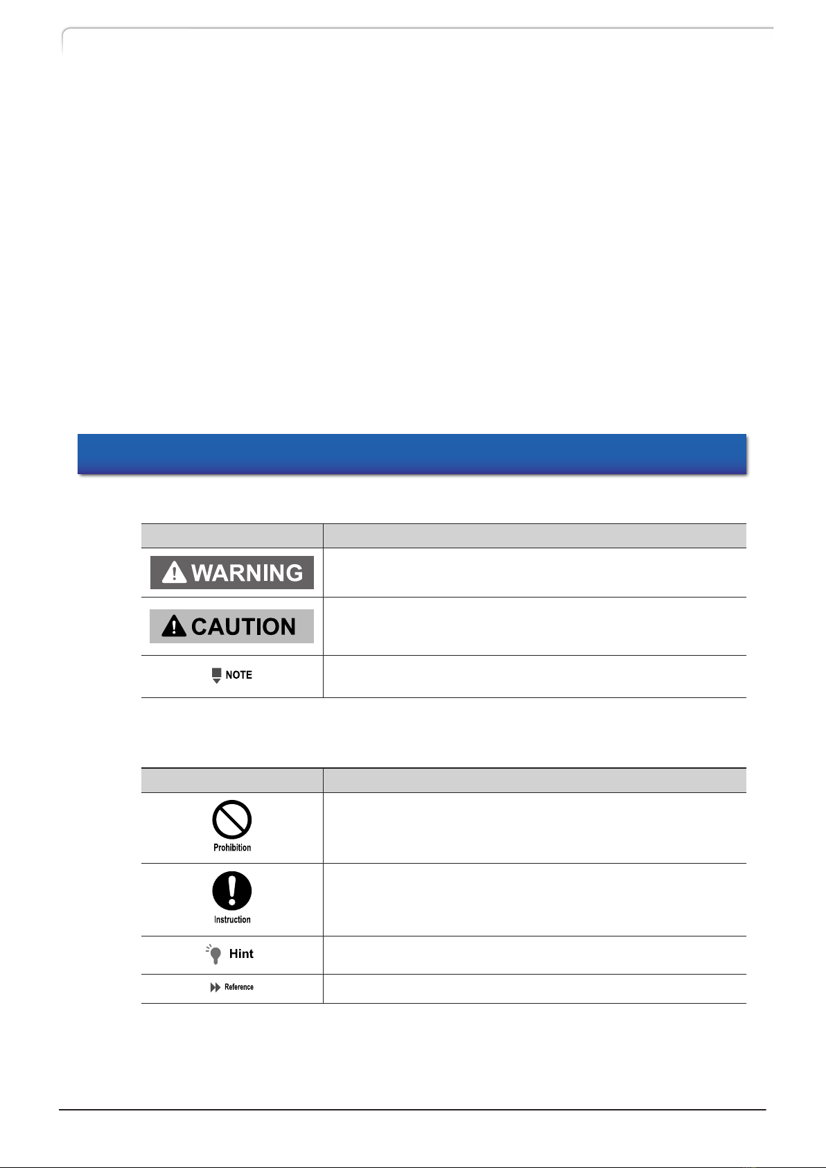
Precaution symbols are indicated using the following conventions:
Indication Meaning
Indicates a potentially hazardous situation which, if not
avoided, could result in serious injury or possibly death.
Indicates a potentially hazardous situation which, if not
avoided, may result in minor to moderate injury or equipment
damage.
Emphasizes additional information that is provided to ensure
the proper use of this product.
The following symbols are used in this manual:
Indication Meaning
Indicates an action that must not be performed.
Indicates an action that must be performed.
Indicates information provided to improve product performance.
Indicates the location of related reference information.
ii CTO-40C CL
Introduction

Operating Nexera CL System
nIntended Use
This system is designed to perform qualitative and quantitative analysis of target
compounds in a sample matrix and can be used as a column oven of the liquid
chromatograph for general in vitro diagnostic applications. However, only personnel who
have received appropriate training on use of the system can use it for these purposes.
nCalibration
A calibration curve should be generated for each analyte in appropriate methods. At
least four out of six non-zero standards should meet the appropriate criteria, including
the calibration standard lower than the assumed LOQ and the calibration standard at
the highest concentration.
nQuality Control
Implement quality control of the instrument by routinely measuring at least one each of
four types of quality-control samples (a sample with a normal concentration level, a
sample with a concentration level higher than normal as well as a sample lower than
normal, and a blank sample). Check the selectivity/specificity in the matrix used for the
actual sample, the accuracy, correctness, recovery rate, dynamic range, linearity, and lower
limit of quantitation.
Based on these assessment results, check that the results are within the permissible range.
If the assessment results are out of range, the measured data may be invalid, so do not
use analysis results obtained from the instrument in question until it can be confirmed
that it is functioning normally. When, for example, analyzing samples that contain
complex sample matrices such as serum, plasma or urine, it may be possible to obtain
stabilized data by using an appropriate pre-treatment or an internal standard.
Electromagnetic Compatibility
Descriptions in this section apply only to the following model:
• 228-65202-55 CTO-40C CL
This product complies with European standard EN61326, class B for electromagnetic
interference (Emissions) and industrial electromagnetic environment (Immunity).
nEN55011 Emissions (Electromagnetic Interference)
This is a class B product. When this product causes an electromagnetic disturbance to
devices being used near this product, create an appropriate distance between those
devices and this product in order to eliminate the disturbance.
CTO-40C CL iii
Operating Nexera CL System

Contents
Introduction Indications Used in This Manual ......................... ii
Operating Nexera CL System .............................. iii
Electromagnetic Compatibility ............................ iii
1Overview 1.1 Features ............................................................. 1
1.2 Component Parts ................................................. 2
1.3 Optional Parts ..................................................... 2
2Parts Identification
and Function
2.1 Front .................................................................. 6
2.2 Interior ............................................................... 8
2.3 Back ................................................................... 9
2.4 Name and Functions of the Operation Panel ....... 10
2.4.1 Display Area ................................................... 12
2.4.2 Operation Area ................................................ 13
3Operation 3.1 Settings for the Basic Operation ......................... 15
3.1.1 Prior to Key Operation ........................................ 15
3.1.2 Temperature Control Operation ............................... 15
3.2 Types of Screens ................................................ 18
3.3 Monitoring Screens ............................................ 19
3.4 Auxiliary Functions Screen (FUNCTION) ................ 20
3.4.1 Auxiliary Functions (FUNCTION) List .......................... 20
3.4.2 [PARAMETER] Setting Group .................................. 23
3.4.3 [SYSTEM] Setting Group ...................................... 24
3.4.4 [UTILITY] Setting Group ....................................... 29
3.5 VP Functions Screen ........................................... 31
3.5.1 List of VP Functions .......................................... 31
3.5.2 Product Information Group (PRODUCT INFO) ................ 32
3.5.3 Maintenance Information Group (MAINTENANCE) ........... 33
3.5.4 Validation Support Information Group (VALIDATION) ........ 35
3.5.5 Calibration Support Information Group (CALIBRATION) ...... 38
iv CTO-40C CL

3.6 Creating Time Program ...................................... 43
3.6.1 Time Program Command List ................................. 43
3.6.2 Time Program Setting Screen ................................. 44
3.6.3 Creating a Time Program ..................................... 45
3.6.4 Deleting a Step ............................................... 47
3.6.5 Starting and Stopping a Time Program ...................... 48
3.6.6 Special Commands Used in Time Programs .................. 49
3.7 Connection with the System Controller ............... 50
3.7.1 Setting the Instrument ........................................ 50
3.7.2 Basic Parameters .............................................. 50
3.8 Connection to External Input/Output Terminals
......................................................................... 51
3.8.1 External Input/Output Terminals .............................. 51
3.8.2 Connection of Remote Cable ................................. 53
4Maintenance 4.1 Periodic Inspection and Maintenance .................. 54
4.1.1 Prior to Inspection and Maintenance ......................... 55
4.1.2 List of Periodic Inspection and Maintenance ................. 55
4.1.3 Check After Inspection and Maintenance .................... 56
4.2 Temperature Accuracy Calibration ....................... 56
4.3 Gas Sensor Calibration ....................................... 57
4.4 Leak Sensor Calibration ...................................... 57
4.5 Cleaning the Leak Tray ...................................... 58
4.6 Replacing the Air Filter ...................................... 58
4.7 Cleaning the Exterior ....................................... 59
4.7.1 Usual cleaning ............................................... 59
4.7.2 Decontamination cleaning ..................................... 60
5Technical
Information
5.1 Specifications .................................................... 61
5.2 Maintenance Parts ............................................. 62
5.2.1 Consumable Parts ............................................. 62
5.2.2 Replacement Parts ............................................. 62
CTO-40C CL v
Contents


The Shimadzu CTO-40C CL column oven was developed to maintain the temperature of
the LC system column and flow lines at a constant temperature, in order to provide
heightened analysis reproducibility and separation performance. The oven is an
air-circulated thermostatic chamber for the Shimadzu Liquid Chromatography system. In
this instrument, the temperature is controlled by a heater for heating and a Peltier
element for cooling, and the temperature around the column is kept uniform by agitating
the inside of the thermostatic chamber with an air circulation fan.
Excluding the thermostatic chamber, the other instruments necessary for liquid
chromatography such as a solvent delivery unit, autosampler, detector, and system
controller are sold separately.
For instruments that suit your purpose of use, contact your Shimadzu representative.
1.1 Features
nIn addition to columns, the thermostatic chamber allows installation of flow line parts
in it including a mixer and automatic column switch valves.
The main purpose of this column oven is to keep the column temperature constant. The
thermostatic chamber can store flow line parts in it including a mixer and automatic
column switch valves as well as columns. Installing these in the oven isolates them from
the influence of ambient temperature and makes for more stable analysis. Shorter
plumbing distances also reduce dead volume in the flow lines.
nTime program functions are available for setting the temperature even in standalone
use.
Use of a system controller (CBM-40 CL) permits finer control, like starting analysis when
temperature stabilizes and stopping analysis when leaks or problems are detected.
nThe automatic speed control of the air circulation fan provides a stable temperature
control.
The speed of the air circulation fan is automatically controlled based on the temperature
setting. At high temperatures, the air circulation ratio is increased to keep the
temperature constant, and at temperatures close to the ambient temperature, the air
circulation ratio is decreased to suppress heat generation due to the air circulation. The
fan speed is controlled so as to remain constant even when there are fluctuations in the
power supply. This enables stable temperature control.
nThe built-in thermal fuse and leak sensor ensure safety.
To ensure safe use, the thermal fuse cuts off the power to the heater if the temperature
rises abnormally. In addition, if some liquid leaks inside, the gas sensor (flammable
organic solvent) or liquid leak sensor (aqueous solvent) issues an error to automatically
stop temperature control.
1Overview
CTO-40C CL 1
1

1.2 Component Parts
This instrument consists of the standard parts listed below. Check the parts against this
list after unpacking.
No. Part Name Part No. Q'ty Remark
- Main Unit CTO-40C CL - 1 -
-Safety Guideline
(Booklet) 228-97195 1 Contains cautions for use
regarding the instrument.
-
Instruction Manual/
System Guide
(CD-ROM)
228-97193-41 1
1 Filter holder 228-72234 1
System Guide "7
Installation"
2 Air filter 228-72570-01 1
3 Drain Tube 228-25162-03 1
4 Rubber column clamp 228-72586 2
5 Clamp CKN-10-R 072-60330-53 1
6 Clamp DKN-10GSP 072-60319-01 1
1.3 Optional Parts
Optional parts which can be added to the column oven are listed below.
For information about other optional units listed below, contact your Shimadzu
representative.
For optional parts for the whole LC system, refer to System Guide. For columns, refer to
Shimadzu's column catalog.
nParts for the oven
Option Part No. Features
Active preheater 228-72084-41
The preheating unit heats the mobile phase
before it enters columns by independent
heating control. The unit controls the
temperature gradient in columns so that sharp
peaks are obtained.
Column clamp B5 228-15617-41 Can fix one column with an outer diameter of
6.5 mm to 9.5 mm. (Metal)
Column clamp B8 228-15617-42 Can fix one column with an outer diameter of
9.5 mm to 12.7 mm. (Metal)
Column catch 228-28637-91 Can fix two columns with an outer diameter of
6.5 mm to 12.7 mm. (Metal)
Remote Cable 228-28253-91 Used for connection of an external device.
2CTO-40C CL
1 Overview
nCMD (Column Management Device)
The device stores information on a column and is capable of managing the column in
combination with the database of a PC workstation. One CMD chip is required for each
column. For details, refer to the instruction manual of LabSolutions chromatography data
system.
System Guide "3.9 Column Management"
Option Part No. Features
CMD (Column
Management Device) 228-37281-41 The device is stored colmun-related infomation.
One CMD chip is required for each column.
CMD cable (150 mm) 228-39991 The cable connects a CMD chip with the
instrument.
CMD cable (400 mm) 228-39991-01
nAutomatic column switch valve
Two valves can be installed with one on the lower-left part and the other on the
lower-right part.
Option Part No. Features
FCV-0206H 228-65607-58
The valve with two positions and six ports
automatically switches between two columns.
The withstand pressure is 80 MPa.
FCV-0206H3 228-65624-58
The valve with two positions and six ports
automatically switches between two columns.
The withstand pressure is 130 MPa.
FCV-0607H 228-65608-58
The valve with six positions and seven ports
automatically switches between six columns.
The withstand pressure is 80 MPa.
FCV-0607H3 228-65625-58
The valve with six positions and seven ports
automatically switches between six columns.
The withstand pressure is 130 MPa.
FCV-DR 228-65602-58 The unit drives the previously listed valves. (One
unit is required for each valve.)
FCV-36AH 228-45206-58
The valve with two positions and ten ports
automatically switches between two columns.
The withstand pressure is 100 MPa. (Including
the driving unit)
Manifold 228-72436-41
The part joins tubes of column outlets to
enable one valve to switch between columns.
PEEK resin is used for a wetted part.
Safety GuidelineSystem Guide "5.
Precautions for Mobile Phase Selection
and Use"
FCV installation kit
(CTO-40C) 228-72589-41
The common installation kit is required for
installing the previously listed valves in the
instrument. (Only one unit is required for this
instrument.)
FCV tubing two-piece kit
(ID 0.3) 228-72437-41 The tubing kit is required for installing two
columns.
CTO-40C CL 3
1.3 Optional Parts
1

Option Part No. Features
FCV tubing two-piece kit
(ID 0.1) 228-72437-42 The tubing kit is required for installing two
columns.
FCV tubing two-piece kit
(ID 0.1 300 mm Nexlock) 228-72437-49
The tubing kit is required for installing two
columns. (This Nexlock tubing comes with finger
tight fittings.)
FCV tubing six-piece kit
(ID 0.3) 228-72437-43 The tubing kit is required for installing two to
six columns.
FCV tubing six-piece kit
(ID 0.1) 228-72437-44 The tubing kit is required for installing two to
six columns.
FCV tubing six-piece kit
(ID 0.1 300 mm Nexlock) 228-72437-50
The tubing kit is required for installing two to
six columns. (This Nexlock tubing comes with
finger tight fittings.)
4CTO-40C CL
1 Overview

nGradient mixer
The instrument can store one of the following mixers coming with a mixer detection
device.
For how to select a mixer, refer to System Guide.
Connecting a mixer detection device to the instrument requires a separate CMD cable
(150 mm).
Option Part No. Features
MIXER SUS316L ASSY
(With a mixer detection
device)
228-72654-41
The general-purpose mixer, where stainless steel
is used for the wetted part material, is intended
for both high and low pressure gradient
analysis. The capacity can switch between three
settings of 0.5 mL, 1.7 mL, and 2.6 mL.
MIXER PEEK
(With a mixer detection
device)
228-72654-42
The non-metal gradient mixer does not contain
any metal as a material in its parts that come
in contact with liquid. The capacity can switch
between two settings of 0.4 mL and 1.6 mL.
The mixer can be used for both high and low
pressure gradient analysis.
MIXER MR 20 µL
(With a mixer detection
device)
228-72652-41
The mixer is intended exclusively for high
pressure gradient analysis with high
performance and a small internal capacity of 20
μL, where stainless steel is used for the wetted
part material.
MIXER MR 40 µL
(With a mixer detection
device)
228-72652-42
The mixer is intended exclusively for high
pressure gradient analysis with high
performance and a small internal capacity of 40
μL, where stainless steel is used for the wetted
part material.
MIXER MR 100 µL
(With a mixer detection
device)
228-72652-43
The mixer is intended exclusively for high
pressure gradient analysis with high
performance and a small internal capacity of
100 μL, where stainless steel is used for the
wetted part material.
MIXER MR 180 µL II
(With a mixer detection
device)
228-72652-44
The mixer is intended exclusively for high
pressure gradient analysis with high
performance and a small internal capacity of
180 μL, where stainless steel is used for the
wetted part material.
MIXER MR 300 LPGE
(With a mixer detection
device)
228-72653-42
The high performance mixer is intended
exclusively for low pressure gradient analysis
with an internal capacity of 300 μL, where
stainless steel is used for the wetted part
material.
CTO-40C CL 5
1.3 Optional Parts
1
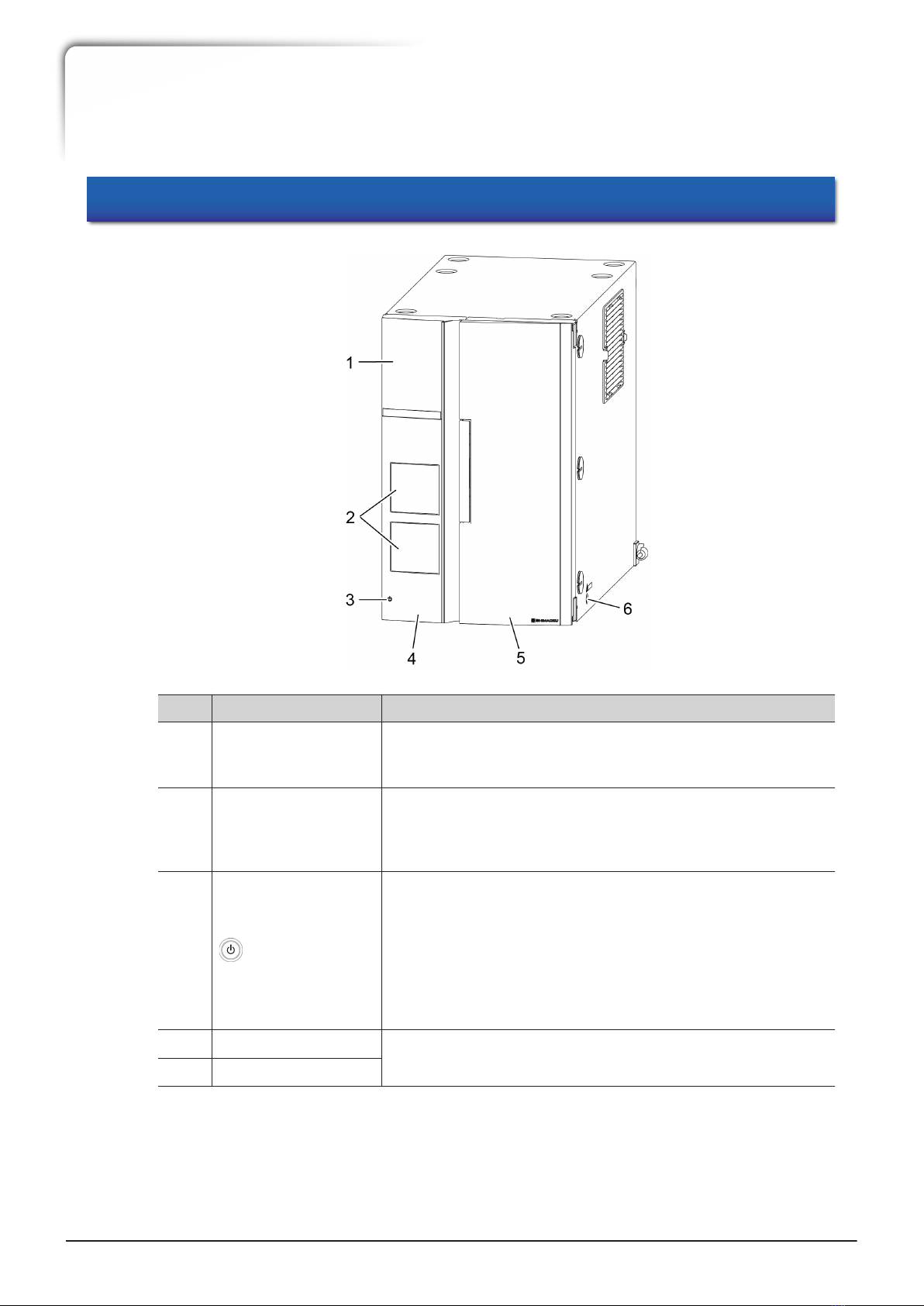
2.1 Front
No. Name Function
1 Operation panel
Configure or operate the instrument with the operation keys.
Touching any other point than the display area on the
operation panel displays the operation keys.
2
Manual injector
(optional) positions
(Not used in CL
model)
Manual injectors (optional) can be installed here after
removing the covers.
3 (Power button)
Switches ON/OFF the power. When the power is ON, the
switch illuminates in white, and when the power is OFF, the
switch illuminates in orange. Even when the power is OFF,
the standby current is fed to the instrument. For the main
power, see "2.3 Back" P.9.
Note that, with a system controller CBM-40 CL connected,
the switch does not illuminate and the operation to the
switch is ignored.
4 Left door The door of the column temperature control part. Open the
door when setting a column.
5 Right door
2
Parts Identification and Function
6CTO-40C CL

No. Name Function
6 Drain hole The hole on the right of the instrument drains dew water
and mobile phase leaking inside.
The right and left doors have a built-in sensor. Opening the door during
temperature control causes the control to be stopped and the [DOOR] indicator
on the display area to blink. Closing the door causes the temperature control to
be resumed.
CTO-40C CL 7
2.1 Front
2
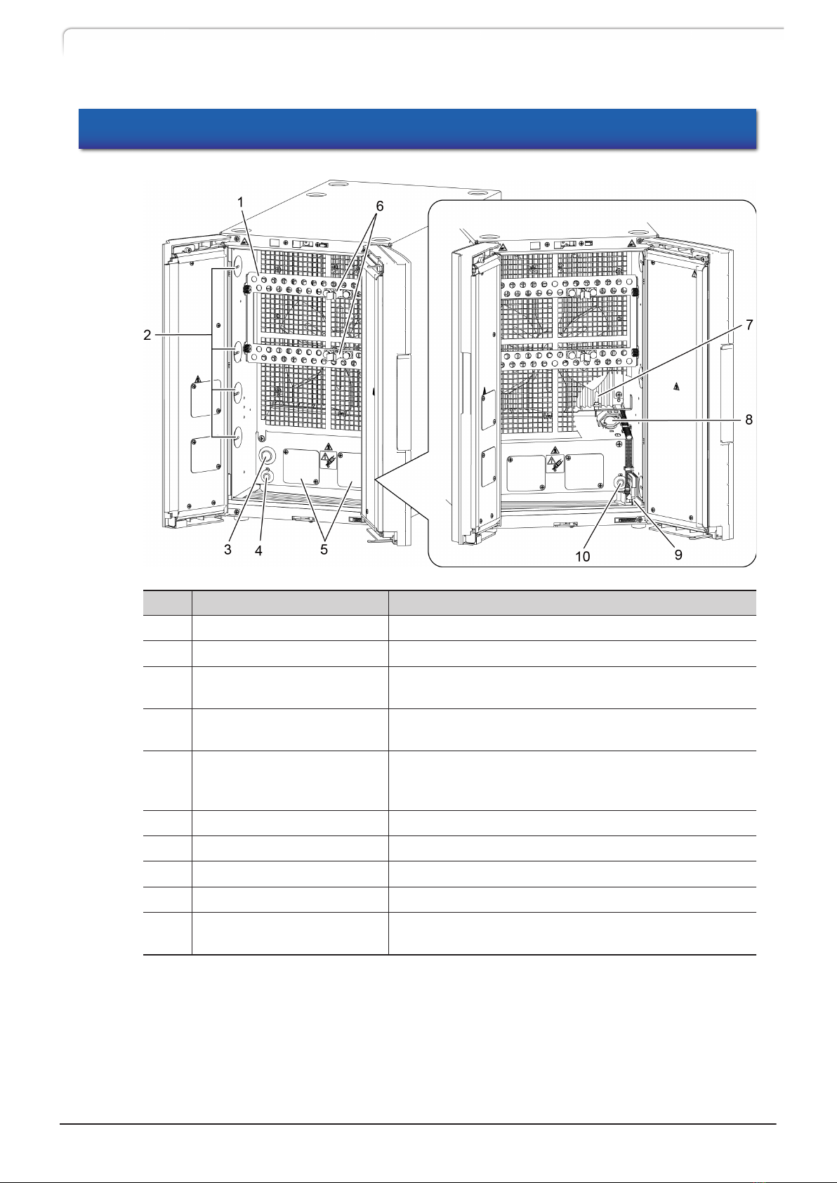
2.2 Interior
No. Name Function
1 Column bracket Used for fixing columns.
2 Tube cap Removing the caps allows inserting tubes.
3 Optional hole cap Used for installation of an optional active preheater
and multi-column rack.
4 [CMD4/Mixer] connector The connector is for a mixer detection device
(optional). ([CMD4] is a future expanded function.)
5
Automatic column switch
valve (optional) installation
part
Allows installation of the optional automatic column
switch valves.
6 Column clamp Used for fixing tubes.
7 Thermosensor The sensor is for temperature measurement.
8 Gas sensor The sensor detects organic solvent vapors.
9 Liquid leak sensor The sensor detects leakage of aqueous solvent.
10 [CMD1] connector The connector is for a column management device
(CMD) (optional).
8CTO-40C CL
2 Parts Identification and Function
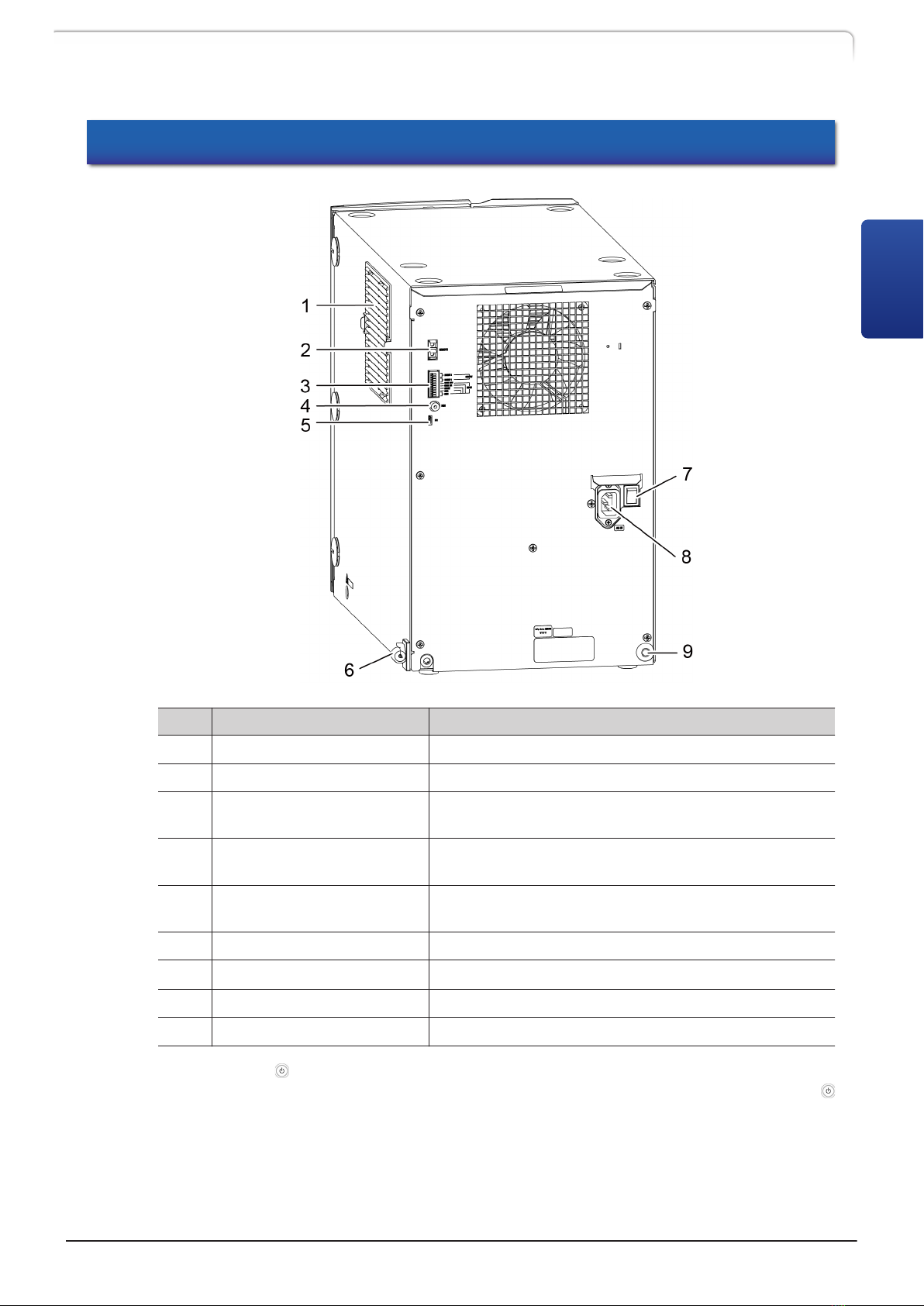
2.3 Back
No. Name Function
1 Air filter Prevents dust from entering the instrument.
2 [REMOTE] connector Connect to the system controller.
3External input/output
terminals Connect to external equipment.
4 [REC] connector The connector outputs the signal of column oven
temperature (100 °C/mV).
5 [PC] connector Connector for service personnel. Normally, this is not
used.
6 Room temperature sensor Monitors the room temperature.
7 Main power switch It turns on/off the power to the instrument.*1
8 Power cord connector Connect the power cord.
9 External-device hole cap Used for attaching an external device.
*1 Normally use (power button) of the operation panel or system controller to turn ON/OFF the
power. If the system controller is connected and the main power switch is on, the user can use
(power button) of the system controller to turn ON/OFF the power from the front of the instrument.
If the instrument is not used for a long time, turn off the main power switch. Before turning off
the main power switch, be sure to turn OFF the power using the power button.
CTO-40C CL 9
2.3 Back
2

2.4 Name and Functions of the Operation Panel
This instrument is controlled through the keypad of the operation area. The display area
allows verification of the instrument status.
The operation area has two input modes: [Arrow key input mode] to enable screen
transfer, and [Numerical key input mode] to enable value input.
In a screen where the numeric keys are available, pressing [Enter] switches the operation
area between the modes.
When turning off the main power switch on the back of the instrument after
changing the parameters via panel operation, be sure to turn OFF the power
with the power button at the front of the instrument, and turn off the main
power switch. Otherwise, some of the changed parameters may return to their
original values.
No. Name Description
1 Display area Displays various screens and settings.
"2.4.1 Display Area" P.12
2 Link LED Illuminates when controlled by the system controller.
3 Status LED
• Blue: analysis in progress
• Green: analysis ready (Temperature control stabilized)
•Yellow: preparation for analysis in progress (Temperature
control yet to be stabilized)
• Red: error
• Orange: sleep mode
10 CTO-40C CL
2 Parts Identification and Function
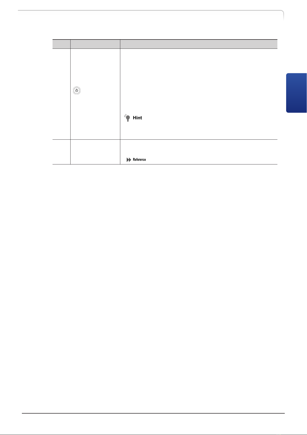
No. Name Description
4 (Power
button) *1
Switches ON/OFF the power.
• To turn the power ON:
Press and hold the power button for at least 3 seconds.
•To turn the power OFF:
Holding down the power button 3 seconds or more displays
the confirmation screen. Holding it down again 1 second turns
off the power.
The button cannot be used if the instrument is connected
with the system controller CBM-40 CL.
When a CBM-40 CL is used, pressing the power button of
the solvent delivery unit connecting CBM-40 CL in it turns
off the power to the whole system.
5 Direct key
Temperature control start/stop, and time program start/stop can
be performed directly.
"2.4.2 Operation Area" P.13
*1 There is the power button in the lower left in the front of this instrument, not on the operation
panel.
CTO-40C CL 11
2.4 Name and Functions of the Operation Panel
2
2.4.1
Display Area
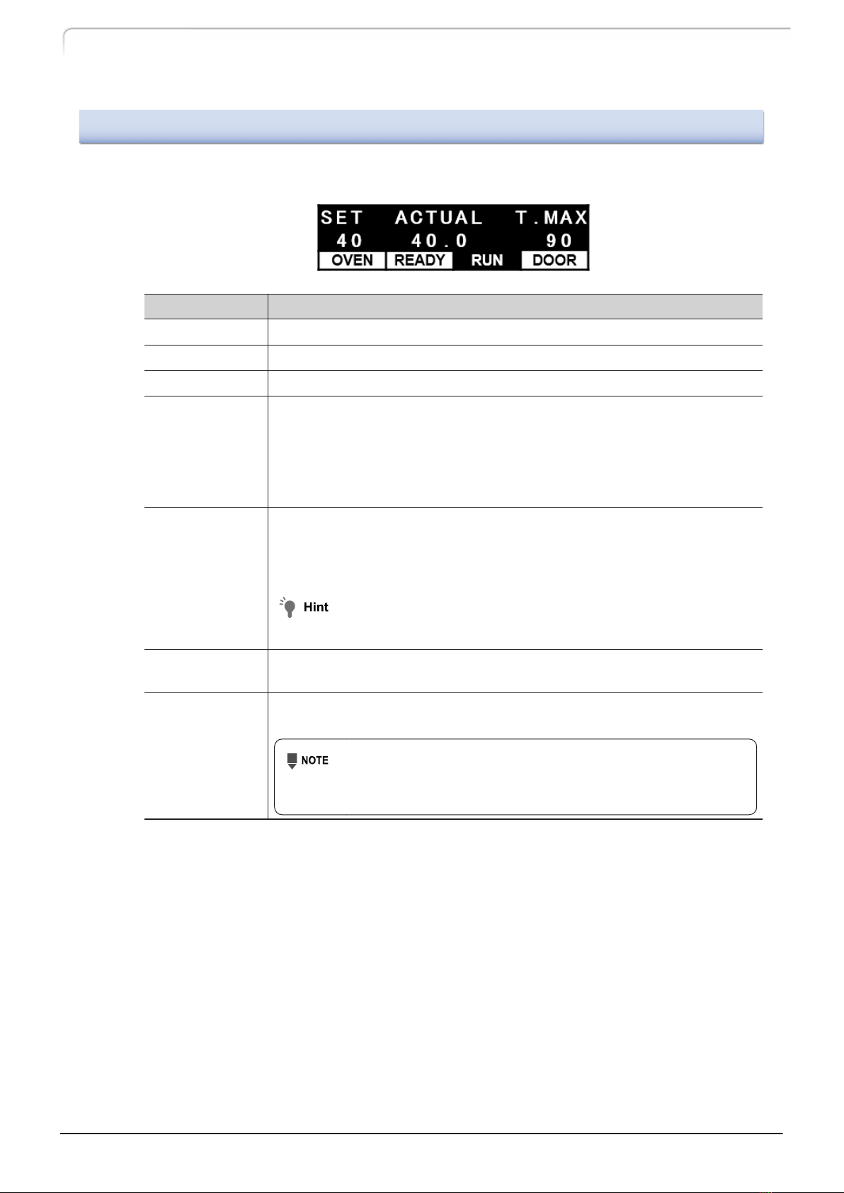
In this section the display on the initial screen is described.
Display Function
SET Displays the setting temperature.
ACTUAL Displays the current operation temperature in the oven.
T.MAX Displays the upper limit value of the temperature.
OVEN
When the oven temperature is in adjustment, the word [OVEN] is
highlighted.
The direct key under the display enables to start or stop the temperature
control, thus pressing it while the temperature control is stopped starts
the adjustment, and pressing it while the adjustment is activated stops
the adjustment.
READY / WAIT
Once the temperature control is completed and stabilized, the word
[READY] is highlighted.
While the temperature control is in preparation, [WAIT] blinks.
While the temperature control is stopped, nothing is displayed.
Users can change the condition to display [READY].
"Setting the temperature ready check《READY CHECK》" P.26
RUN Highlighted during execution of a time program.
The direct key under the indicator starts or stops a time program.
DOOR
Blinks when the front door of the oven unit is opened. When the door
is open, the temperature control is paused.
When the oven temperature is 60 °C or higher, a warning
message is displayed. Closing the door clears the warning
message and resumes the temperature control.
12 CTO-40C CL
2 Parts Identification and Function
Table of contents


