SLS Audio Q-Line Silver User manual


1. Read Instructions - All the safety and operating instructions should
be read before the product is operated.
2. Retain instructions - The safety and operating instructions should
be retained for future reference.
3. Heed Warnings - All warnings on the product and in the operating
instructions should be adhered to.
4. Follow Instructions - All operating and use instructions should be
followed.
5. Cleaning - Unplug this product from the wall outlet before cleaning.
Do not use liquid cleaners or aerosol cleaners. Use a damp cloth for
cleaning.
6. Attachments - Do not use attachments not recommended by the
product manufacturer as they may cause hazards.
7. Water and Moisture - Do not use this product near water - for
example, near a bath tub, wash bowl, kitchen sink, or laundry tub; in
a wet basement, or near a swimming pool; and the like.
8. Accessories - Do not place this product on an unstable cart, stand,
tripod, bracket, or table. The product may fall, causing serious injury
to a child or adult, and serious damage to the product. Use only with
a cart, stand, tripod, bracket, or table recommended by the
manufacturer, or sold with the product. Any mounting of the product
should follow the manufacturer’s instructions, and should use a
mounting accessory recommended by the manufacturer.
9. A product and cart combination should be moved with care. Quick
stops, excessive force, and uneven surfaces
may cause the product and cart combination
to overturn.
10. Ventilation - Slots and openings in the
cabinet are provided for ventilation and to
ensure reliable operation of the product and
to protect it from overheating, and these
openings must not be blocked or covered.
The openings should never be blocked by
placing the product on a bed, sofa, rug, or other similar surface.
This product should not be placed in a built-in installation such as a
bookcase or rack unless proper ventilation is provided or the
manufacturer’s instructions have been adhered to.
11. Power Sources - This product should be operated only from the
type of power source indicated on the marking label. If you are not
sure of the type of power supply to your home, consult your product
dealer or local power company. For products intended to operate
from battery power, or other sources, refer to the operating
instructions.
12. Grounding or Polarization - This product may be equipped with a
polarized alternating-current line plug (a plug having one blade
wider than the other). This plug will fit into the power outlet only one
way. This is a safety feature. If you are unable to insert the plug
fully into the outlet, try reversing the plug. If the plug should still fail
to fit, contact your electrician to replace your obsolete outlet. Do not
defeat the safety purpose of the polarized plug.
Alternate Warnings - This product is equipped with a three-wire
grounding-type plug, a plug having a third(grounding) pin. This plug
will only fit into a grounding-type power outlet. this is a safety
feature. If you are unable to insert the plug into the outlet, contact
your electrician to replace your obsolete outlet. Do not defeat the
safety purpose of the grounding-type plug.
13. Power-Cord Protection - Power-supply cords should be routed so
that they are not likely to be walked on or pinched by items placed
upon or against them, paying particular attention to cords at plugs,
convenience receptacles, and the point where they exit from the
product.
14. Outdoor Antenna Grounding - If an outside antenna or cable
system is connected to the product, be sure the antenna or cable
system is grounded so as to provide some protection against
voltage surges and built-up static charges. Article 810 of the
National Electrical Code, ANSI/NFPA 70, provides information with
regard to proper grounding of the mast and supporting structure,
grounding of the lead-in wire to an antenna discharge unit, size of
grounding conductors, location of antenna-discharge unit,
connection to grounding electrodes, and requirements for the
grounding electrode. See Figure 1.
15. Lightning - For added protection for this product during a lightning
storm, or when it is left unattended and unused for long periods of
time, unplug it from the wall outlet and disconnect the antenna or
cable system. This will prevent damage to the product due to
lightning and power-line surges.
16. Power Lines - An outside antenna system should not be located in
the vicinity of overhead power lines or other electric light or power
circuits, or where it can fall into such power lines or circuits. When
installing an outside antenna system, extreme care should be taken
to keep from touching such power lines or circuits as contact with
them might be fatal.
17. Overloading - Do not overload wall outlets, extension cords, or
integral convenience receptacles as this can result in a risk of fire or
electric shock.
18. Object and Liquid Entry - Never push objects of any kind into this
product through openings as they may touch dangerous voltage
points or short-out parts that could result in a fire or electric shock.
Never spill liquid of any kind on the product.
19. Servicing - Do not attempt to service this product yourself as
opening or removing covers may expose you to dangerous voltage
or other hazards. Refer all servicing to qualified service personnel.
20. Damage Requiring Service - Unplug this product form the wall
outlet and refer servicing to qualified service personnel under the
following conditions:
a) When the power-supply cord or plug is damaged,
b) If liquid has been spilled, or objects have fallen into the product,
c) If the product has been exposed to rain or water,
d) If the product does not operate normally by following the
operating instructions. Adjust only those controls that are
covered by the operating instructions as an improper adjustment
of other controls may result in damage and will often require
extensive work by a qualified technician to restore the product to
its normal operation.
e) If the product has been dropped or damaged in any way, and
f) When the product exhibits a distinct change in performance - this
indicates a need for service.
21. Replacement Parts - When replacement parts are required, be
sure the service technician has used replacement parts specified by
the manufacturer or have the same characteristics as the original
part. Unauthorized substitutions may result in fire, electric shock, or
other hazards.
22. Safety Check - Upon completion of any service or repairs to this
product, ask the service technician to perform safety checks to
determine that the product is in proper operating condition.
23. Wall or Ceiling Mounting - The product should be mounted to a
wall or ceiling only as recommended by the manufacturer.
24. Heat - The product should be situated away from heat sources
such as radiators, heat registers, stoves, or other products
(including amplifiers) that produce heat.
SAFETY INSTRUCTION
ENGLISH
1
2
Introduction
READ THIS BEFORE OPERATING YOUR UNIT
: TO REDUCE THE RISK OF
ELECTRIC SHOCK, DO NOT
REMOVE COVER (OR BACK). NO
USER-SERVICEABLE PARTS
INSIDE. REFER SERVICING TO
QUALIFIED SERVICE PERSONNEL.
: TO REDUCE THE RISK OF FIRE OR ELECTRIC SHOCK,
DO NOT EXPOSE THIS APPLIANCE TO RAIN OR MOISTURE.
CAUTION
WARNING
This symbol is intended to alert the user to the
presence of uninsulated "dangerous voltage"
within the product's enclosure that may be of
sufficient magnitude to constitute a risk of
electric shock to persons.
This symbol is intended to alert the user to the
presence of important operating and
maintenance (servicing) instructions in the
literature accompanying the appliance.
Units shipped to the U.S.A and Canada are designed for operation on 120 V AC only.
Safety precaution with use of a polarized AC plug.
However, some products may be supplied with a nonpolarized plug.
: To prevent electric shock, match wide blade of plug to wide slot, fully
insert.
: Pour éviter chocs électriques, introduire la lame la plus large de la
fiche dans la borne correspondante de la prise et pousser jusqu’ au
fond.
FOR YOUR SAFETY
U.S.A
CANADA 120 V
• Avoid high temperatures. Allow for sufficient heat dispersion when installed on a rack.
• Keep the set free from moisture, water, and dust.
• Do not let foreign objects in the set.
• Handle the power cord carefully. Hold the plug when unplugging the cord.
• Unplug the power cord when not using the set for long periods of time.
• Do not obstruct the ventilation holes.
• Do not let insecticides, benzene, and thinner come in contact with the set.
• Never disassemble or modify the set in any way.
Note to CATV System Installer :
This reminder is provided to call the CATV system installer’s attention to Article 820-40 of the NEC that provides
guidelines for proper grounding and, in particular, specifies that the cable ground shall be connected to the
grounding system of the building, as close to the point of cable entry as practical.
FCC INFORMATION
This equipment has been tested and found to comply with the limits for a Class B digital device, pursuant to Part 15 of
the FCC Rules. These limits are designed to provide reasonable protection against harmful interference in a residential
installation. This equipment generates, uses and can radiate radio frequency energy and, if not installed and used in
accordance with the instructions, may cause harmful interference to radio communications. However, there is no
guarantee that interference will not occur in a particular installation. If this equipment does cause harmful interference to
radio or television reception, which can be determined by turning the equipment off and on, the user is encouraged to
try to correct the interference by one or more of the following measures:
• Reorient or relocate the receiving antenna.
• Increase the separation between the equipment and receiver.
• Connect the equipment into an outlet on a circuit different from that to which the receiver is connected.
• Consult the dealer or an experienced radio/TV technician for help.
Caution : Any changes or modifications in construction of this device which are not expressly approved by the party
responsible for compliance could void the user’s authority to operate the equipment.
CAUTION
ATTENTION
ENGLISH

3
CONTENTS
Introduction
• SAFETY INSTRUCTION............................................................................................................................. 1
• READ THIS BEFORE OPERATING YOUR UNIT .................................................................................... 2
System Connections........................................................................................................................................ 4
Front Panel Controls...................................................................................................................................... 6
Remote Controls.............................................................................................................................................. 7
• REMOTE CONTROL OPERATION RANGE............................................................................................. 8
• LOADING BATTERIES............................................................................................................................... 8
Operations
• LISTENING TO A PROGRAM SOURCE ................................................................................................... 9
• SURROUND SOUND................................................................................................................................. 12
• ENJOYING SURROUND SOUND ............................................................................................................ 14
• LISTENING TO RADIO BROADCASTS.................................................................................................. 19
• RECORDING............................................................................................................................................... 21
• OTHER FUNCTIONS................................................................................................................................. 22
Troubleshooting Guide ................................................................................................................................23
Specifications.................................................................................................................................................. 24
ENGLISH
4
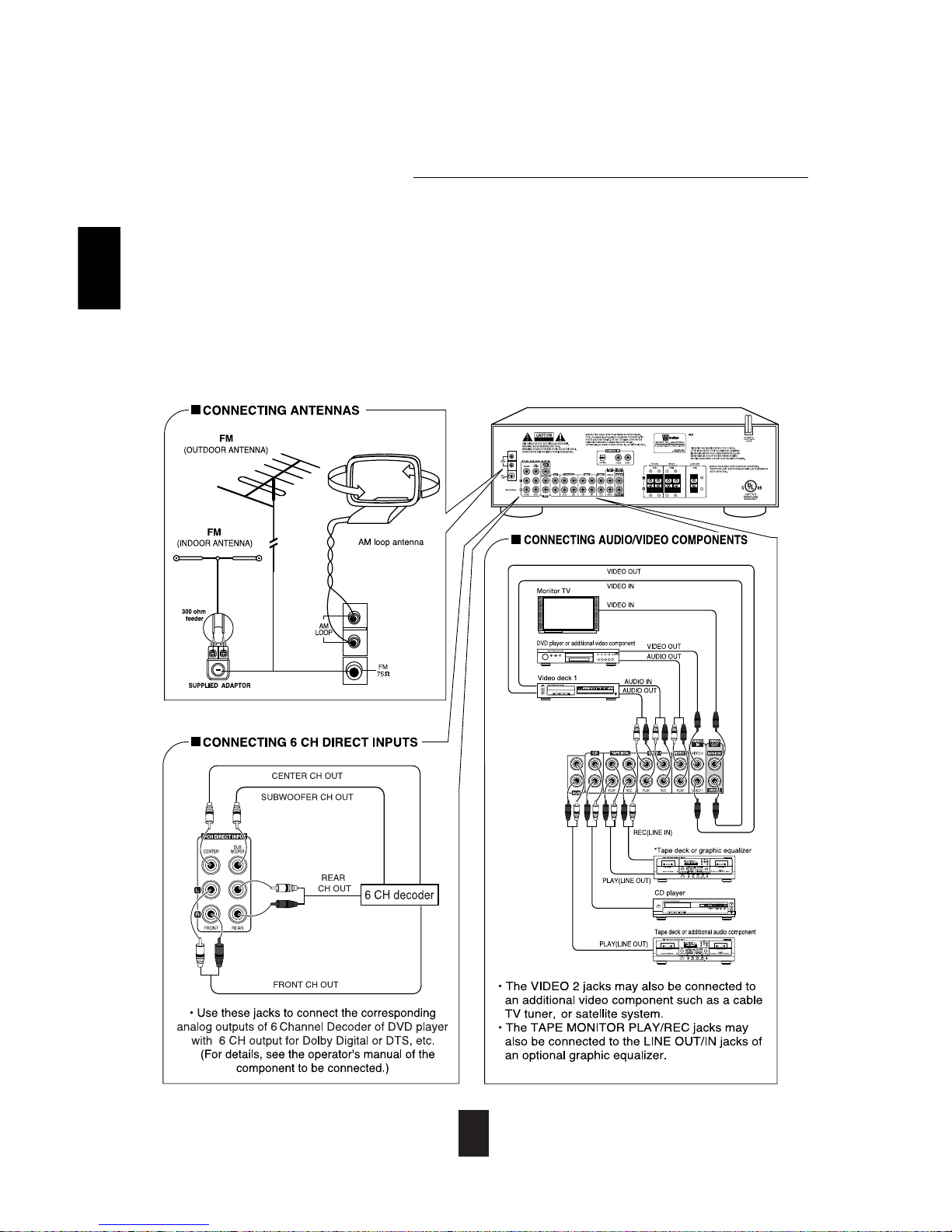
System Connections
• Do not plug the AC input cord into the wall AC outlet until all connections are completed.
• Be sure to observe the color coding when connecting audio and video cords.
• Change the position of the FM indoor antenna until you get the best reception of your favorite FM stations.
• A 75 Ωoutdoor FM antenna may be used to further improve the reception.
Disconnect the indoor antenna before replacing it with the outdoor one.
• Place the AM loop antenna as far as possible from the receiver, TV set, speaker cords and the AC input Cord, and orient for
best reception.
• If the reception is poor with the AM loop antenna, an AM outdoor antenna can be used in place of the AM loop antenna.
• Make connections firmly and correctly. Loose connections can cause loss of signal or damage to receiver.
• If the electricity fails or the AC input cord is left unplugged for more than 2 weeks, the memorized contents will be cleared.
Should this happen, memorize them again.
• Keep product away from sources of heat, direct sunlight, water, rain and moisture. Try to keep antenna wires away from
power cords.
ENGLISH
5
ENGLISH
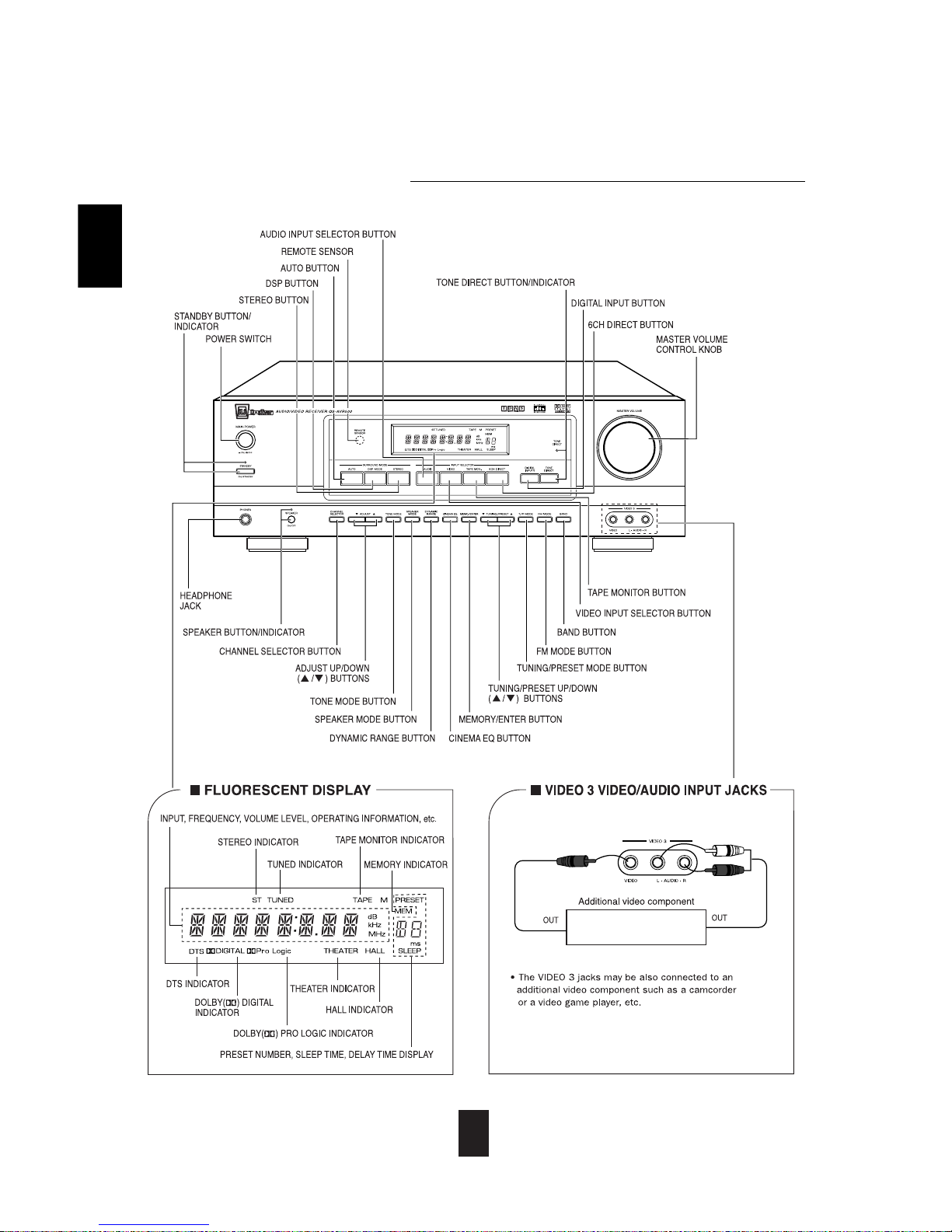
6
Front Panel Controls
ENGLISH

7
Remote Controls
ENGLISH

8
LOADING BATTERIES
REMOTE CONTROL OPERATION RANGE
1 2
• Use the remote control unit within a range of about 7
meters (23 feet) and angles of up to 30 degrees
aiming at the remote sensor.
• Remove the batteries when they are not used for a
long time.
• Do not use rechargeable batteries (Ni-Cd type).
Remove the cover. Load two batteries matching the polarity.
ENGLISH

9
LISTENING TO A PROGRAM SOURCE
Operations
Before operation
Select the desired input source.
3
• Enter standby mode by pressing
MAIN POWER button.
• The STANDBY indicator lights up.
This means that the receiver is connected to the AC
mains and a small amount of current is retained to
support the memorized contents and operation readiness.
• To switch the power off, push the POWER switch again.
• Then the power is cut off and the STANDBY indicator
goes off.
• Each time the STANDBY button on the front panel or
the POWER button on the remote control is pressed,
the receiver is turned on to enter the operating mode
or off to enter the standby mode.
• In the standby mode, if the INPUT SELECTOR
button is pressed, the receiver is turned on
automatically and the desired input is selected.
• Then the SPEAKER indicator lights up and the
sound can be heard from the speakers connected to
the speaker terminals.
• When using the headphone for private listening,
press the SPEAKER button again to switch the
speakers off.
• Each time the “AUDIO” button is pressed, the input
source changes as follows :
TUNER CD AUX
(frequency display)
• Each time the “VIDEO” button is pressed, the input
source changes as follows :
VIDEO 1 VIDEO 2 VIDEO 3
• When the TAPE MONITOR button is pressed, the
“TAPE M” indicator lights up, other inputs can not be
heard from the speakers.
To listen to an input source other than TAPE
MONITOR, be sure to set the TAPE MONITOR
button to off.
TAPE MONITOR function
You can connect either a tape deck or a graphic equalizer to
the receiver’s TAPE MONITOR jacks.
Tape Monitor should only be on when you are listening to a
component connected to the Tape Monitor jacks.
If you connect a 3-head tape deck, you can listen to the sound
being recorded during recording, not the source sound.
For further details, refer to the operating instructions of the
component connected.
Pressing 6CH(annel)DIRECT overrides other input
selections.
• “6-DIRECT” is displayed and the 6 separate analog
signals from 6 CH decoder connected to this unit pass
through the tone (bass, treble) and volume circuits only
and directly transfer to the speakers. (In case that the
TAPE MONITOR button is set to on, the TAPE
MONITOR button is automatically set to off.)
• Press the 6 CH DIRECT button or select the desired
input source to cancel the 6 CH direct function.
• These six separate analog signals can only be heard,
not recorded.
In the standby mode, turn the power on.
1
Switch the speakers on.
2
ENGLISH
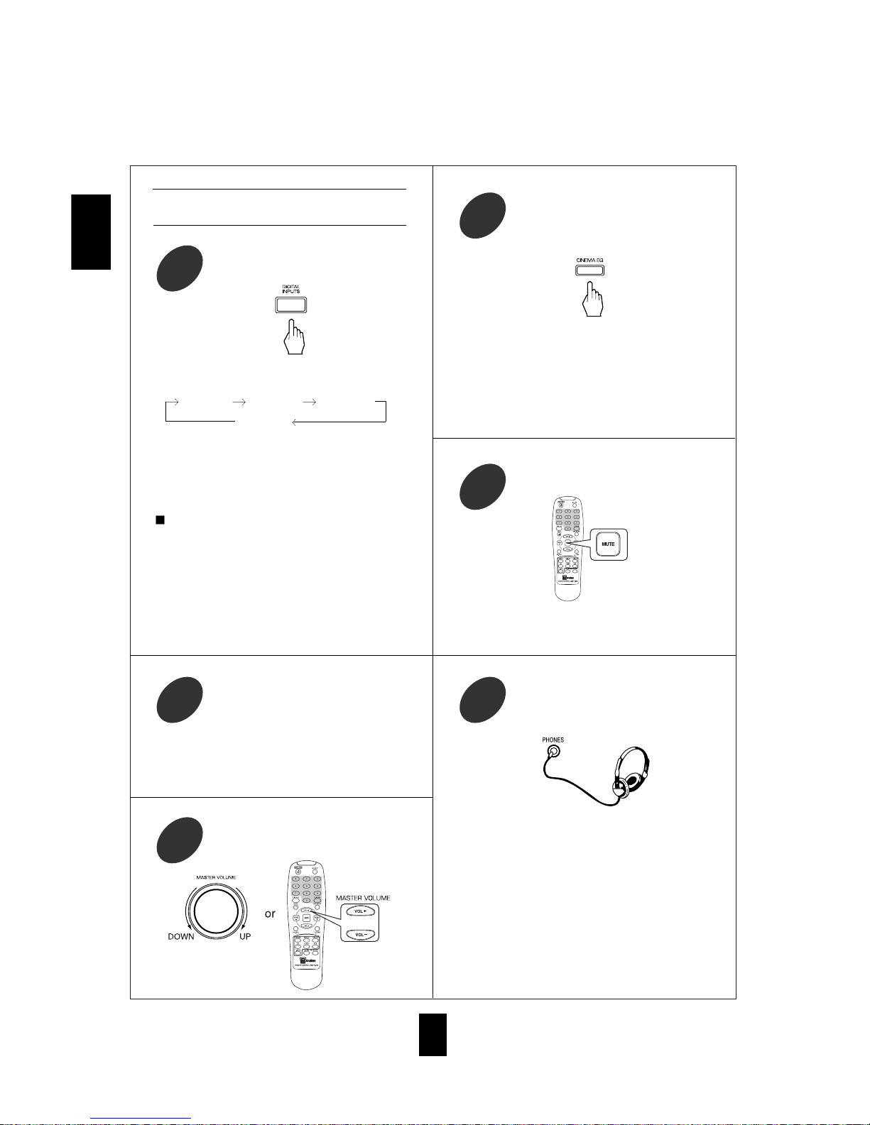
To listen with the headphones.
9
• Ensure that the SPEAKER button is set to off.
• When listening to a DTS or Dolby Digital program
source, if the headphones are plugged in and the
SPEAKER button is set to off, it enters the 2-CH
downmix mode automatically. (For details, refer to
“Downmixing into two front channels”on page 18.)
10
When CD, VIDEO 1~3 is selected as an
input source
Select the digital or analog input
connected as desired.
4
• When playing back the program sources with
surround sound, refer to “ENJOYING SURROUND
SOUND” on page 14.
• Each time this button is pressed, the corresponding
input is selected as follows ;
o(ptical) 1 c(oaxial) 1 c(oaxial) 2
A(nalog)
• To listen to a DTS or Dolby Digital program source
in the 2-CH downmix mode, in the stereo mode, the
corresponding digital input should be selected. (For
details, refer to “Downmixing into two front
channels” on page 18.)
Notes :
• When the selected optical or coaxial digital input is
not connected, the selected digital input display
flickers, indicationg that there is no input signal.
(Refer to “ENJOYING SURROUND SOUND” on
page 14.)
• The sound from the component connected to the
selected digital input can be heard regardless of the
selected input source.
Adjust the (overall) volume.
6
Operate the selected component for
playback.
5
• Then “C-EQ ON” is displayed.
• Press it again to cancel, the “C-EQ OFF” is
displayed.
• When the 6 CH DIRECT is selected as an input
source, the cinema EQ function is bypassed.
To compensate for edgy or shrill movie
sound tracks.
7
• “MUTE” will flicker.
• To resume the previous sound level, press it again.
To mute the sound.
8
ENGLISH

11
• Each time this button is pressed, the corresponding
tone mode is selected and shown for 3 seconds as
follows:
BASS TRBL(treble)
Note: When the TONE DIRECT indicator is lit,
bass and treble settings can not be adjusted.
Enter the tone mode.
10
• When TONE DIRECT indicator lit, tone circuitry
is bypassed.
• To toggle the tone circuitry back on, press button
again.
To listen to a program source without tone
adjustments, press TONE DIRECT button.
12
• If the tone display disappears, start from the step 10
again.
Notes:
• Extreme settings at high volume may damage your
speakers.
• When the digital signals from DTS or Dolby Digital
program sources are input in available surround
mode, the tone controls are bypassed.
At the desired tone mode, adjust the tone
as desired.
11
Adjusting the tone (bass and treble)
ENGLISH
12
SURROUND SOUND
• This receiver incorporates a sophisticated Digital Signal Processor that allows you to enjoy mutichannel
surround sound in your Home Theater.
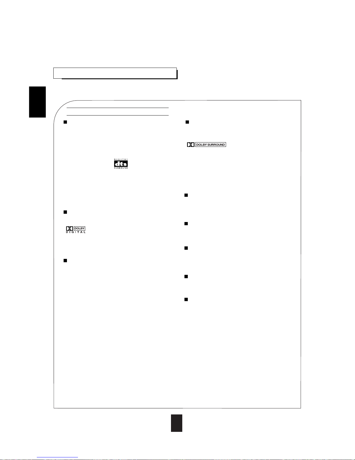
DTS Digital Surround
DTS Digital Surround (also called simply DTS) is a multi-
channel digital signal format which can handle more
amount of data than Dolby Digital, providing better audio
quality. Though the number of audio channels is 5.1 (front
left, front right, center, rear [surround] left, rear [surround]
right and Low Frequency Effects) which is same as Dolby
Digital, discs bearing the “ ” provide high quality
sound and better signal - to - noise ratio, thanks to the lower
audio compression ratio format.
DTS also provides wide dynamic range and better
separation, resulting in magnificent sound.
“DTS” and “DTS Digital Surround” are registered
trademarks of Digital Theater Systems, Inc.
Dolby Digital
Dolby Digital is the multi-channel digital signal format
developed by Dolby Laboratories. Discs bearing the
“ ” include the recording of up to 5. 1 channels
of digital signals, which can reproduce much better sound
quality, spatial expansion and dynamic range characteristics
than the previous Dolby Surround system.
Dolby Pro Logic II surround
This mode applies conventional 2- channel signals such as
digital PCM or analog stereo signals as well as Dolby
Surround signals, etc. to surround processing to offer
improvements over conventional Dolby Pro Logic circuits.
Dolby Pro Logic ll surround includes 4 modes as follows:
• Dolby Pro Logic ll MOVIE
When enjoying movies, this mode allows you to further
enhance the cinematic quality by adding processing that
emphasizes the sounds of the action special effects.
• Dolby Pro Logic ll MUSIC
When listening to music, this mode allows you to further
enhance the sound quality by adding processing that
emphasizes the musical effects.
• Dolby Pro Logic ll MATRIX
When listening to poor FM broadcasts, this mode allows
you to further enhance the sound quality.
• Dolby Pro Logic ll CUSTOM
This mode reproduces delayed signals from the surround
channels to emphasize the sense of spaciousness.
Dolby Pro Logic
Dolby Pro Logic is a specially encoded two channel
surround format which consists of four channels (front
left, center, front right and surround). Sources bearing the
“ ” provide the theater-like surround
sound.
The surround channel is monaural, but is played through
two surround speakers.
The modes below transform conventional two-channel
signals, such as digital PCM or analog stereo, into various
types of there dimensional sound fields.
MATRIX
This mode reproduces a delayed signals from the surround
channels to emphasize the sense of expansion for music
sources.
THEATER
This mode provides the effect of being in a movie theater
when watching a movie source.
HALL
This mode provides the ambience of a concert hall for
classical music sources such as orchestral, chamber music,
or an instrumental solo.
STADIUM
This mode provides the expansive sound field to achieve a
stadium effect while watching baseball or football.
CHURCH
This mode provides the ambience of a church for baroque,
string orchestral or choral group music.
Surround modes
• When the 6 CH DIRECT INPUTs are connected to the 6 CH decoder for a surround sound such as Dolby Digital or DTS,
etc., you can enjoy the corresponding surround sound, too. (For details, see the operator’s manual of the component to be
connected.)
ENGLISH
Manufactured under license from Dolby Laboratories. “Dolby”, “Pro Logic”, and the double-D symbol are trademarks of
Dolby Laboratories.

13
Speaker Setup
To obtain the best surround sound effect in your home,
place the speakers as follows :
• Front speakers: Place each front speaker on each side of
your TV symmetrically so that total
distance between left and right speaker
is no less than 7 feet (2.4 m), with 8-10
feet (2.4 m - 3 m) being best. You can
use included metal stand to place the
speaker on a flat surface. The stand
should be firmly inserted in the provided
slots in the speaker's rear panel. Insert
the stand in corresponding slots for
vertical (front or rear speakers) or
horizontal (center channel speaker)
positioning.
• Center speaker: Place the center speaker either above or
below the TV set to assure good
localization of center channel program.
• Rear speakers: Place rear speakers slightly behind the
listening position angled in toward the
listener, at about 30 degrees (see
diagram). Ideally the speakers should be
positioned symmetrically. The angle
should be calculated between the
direction to the side of the listening place
to the direction on the rear speaker.The
other way to position the rear speakers
correctly is to make sure that the angle
between them is about 120 degrees.
• Reproduction of all movies and music multichannel formats requires all five speakers and subwoofer.
Reproduction of stereo program requires left and right front speakers and subwoofer only.
When the center speaker or the rear speakers are closer to the listener than the front speakers, the sound from the center
speaker or the rear speakers can arrive at the listener’s ears earlier than the sound from the front speakers.
In this case, the imaging is not as sharp and stable as it could be.
For audible improvement, the sound from center speaker can be delayed with the center delay time setting, so that sound
from the front and the center speakers will be heard at the same time. The sound from the rear speakers can be also
delayed, using the rear delay time setting, so that the sound from the front and the rear speakers will also be heard at the
same time. The optimum delay time will vary according to room size and acoustic properties.
• Delay is adjustable in Dolby Digital, Dolby Pro Logic II or Dolby Pro Logic mode. (For details, refer to “Adjusting delay
times of speakers in Dolby Digital, Dolby Pro Logic II or Dolby Pro Logic Mode” on page 18)
Delay time
ENGLISH
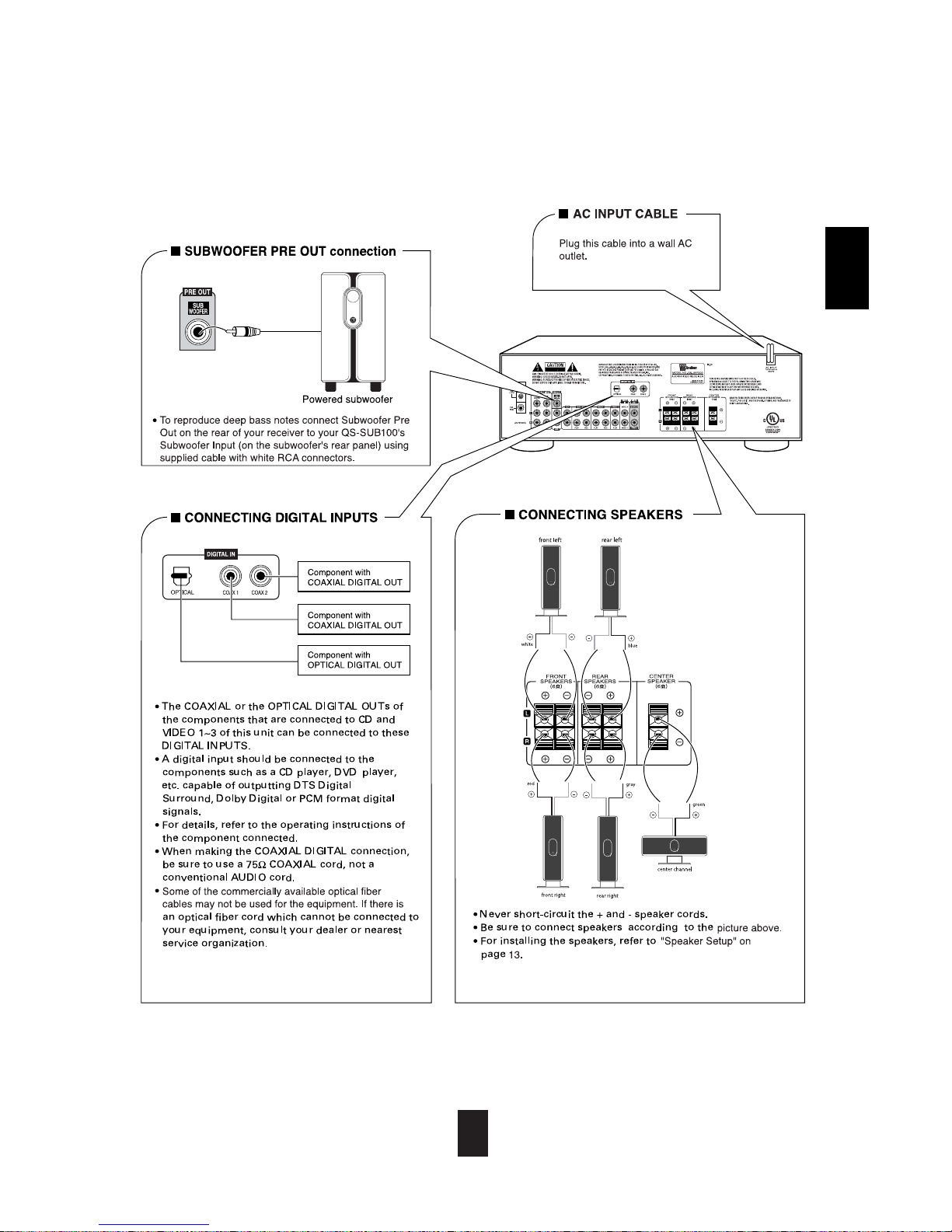
• Subwoofer: Subwoofer is required to reproduce low (bass) notes. The rear panel contains main controls of the
subwoofer. Power ON/OFF switch turns the unit on or off. Phase 0-180 allows to adjust subwoofers phase.
We recommended 0 degrees setting in most cases. If your subwoofer is located further than 5 feet from the
nearest satellite speaker than try switching to 180 degrees to see if you can get a fuller bass in that position.
Auto/ON switch allows either keeping subwoofer ON at all times (ON), or engage a signal sensing network
(Auto) that keeps the subwoofer in stand-by mode if you don't use it and turns it ON automatically when
program starts playing. Volume control is located on the frontal panel. We recommended starting from low
levels and keep adjusting volume until you get a balanced sound and seamless integration between
subwoofer and satellie speakers.
You can place the rear speakers on corner tables or other support using the included stands. You can
also mount them on side or rear wall. The optimum wall mounting height of rear speakers is about
40" (1m), but you can mount them slightly higher of needed.
RECOMMENDED
ALTERNATE
ENGLISH
14
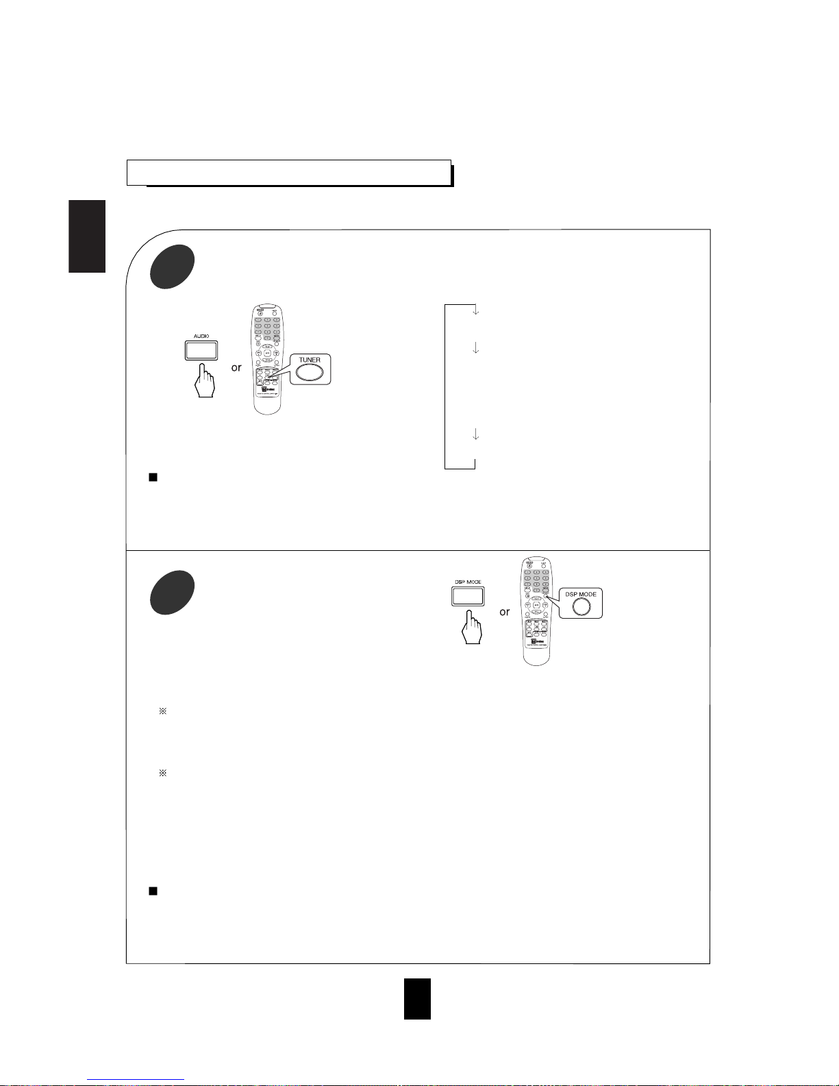
ENJOYING SURROUND SOUND
Depending on the input digital signal
format, select the desired decoding mode.
1
• Surround sound effect will not work properly if the signal passes through a graphic equalizer.
Please refer to your equalizer operating instructions for guidance on switching off (or defeating) the equalizer.
Notes:
• If TUNER, AUX or TAPE MONITOR is selected, the digital decoding modes are bypassed.
• Noise may be generated at the beginning of playback and while searching during DTS playback in the IN-AUTO
mode. In this case, try playing in the IN-DTS mode.
Select the desired surround mode.
2
• Each time the DSP MODE button is pressed, the surround mode changes depending on the input signal format and
the selected decoding mode as follows:
When Dolby Digital signals are input in the IN-AUTO mode, one of the following modes can be selected using the
DSP MODE button, depending on the number of recorded channels present.
• Dolby Digital 5.1-channel sources: DOLBY DIGITAL
• Dolby Digital 2-channel sources: DOLBY PRO LOGIC II MOVIE, DOLBY PRO LOGIC, DOLBY PRO LOGIC II
MUSIC, DOLBY PRO LOGIC II MATRIX and DOLBY PRO LOGIC II CUSTOM
When PCM (2 channel stereo) signals are input in the IN-AUTO or IN-PCM mode, one of the following modes can
be selected :
DOLBY PRO LOGIC II MOVIE, DOLBY PRO LOGIC, DOLBY PRO LOGIC II MUSIC,
DOLBY PRO LOGIC II MATRIX, DOLBY PRO LOGIC II CUSTOM, MATRIX, CHURCH, THEATER, HALL and
STADIUM.
• When analog stereo signals are the input, you can choose any of these surround modes.
• However, when DTS signals are input in the IN-AUTO or IN-DTS mode, the DTS mode will be selected
regardless of use of the DSP MODE button.
Notes:
• When the selected decoding mode is not matched to the input signal format, no sound is heard. Therefore, be sure
to select the required decoding mode and the available surround mode according to the input signal format.
• When the 6 CH DIRECT is selected as an input source, the decoding and surround modes cannot be selected.
• Each time the AUTO button is pressed, the decoding
mode changes as follows:
IN-AUTO : The input digital signal format (DTS,
Dolby Digital or
PCM [2 channel stereo], etc.) used by the
selected digital input source is detected
automatically to perform the necessary
decoding process.
IN-DTS : The DTS signal processing is performed
only when DTS signals are present.
IN-PCM : The PCM signal processing is performed
only when PCM signals are present.
ENGLISH
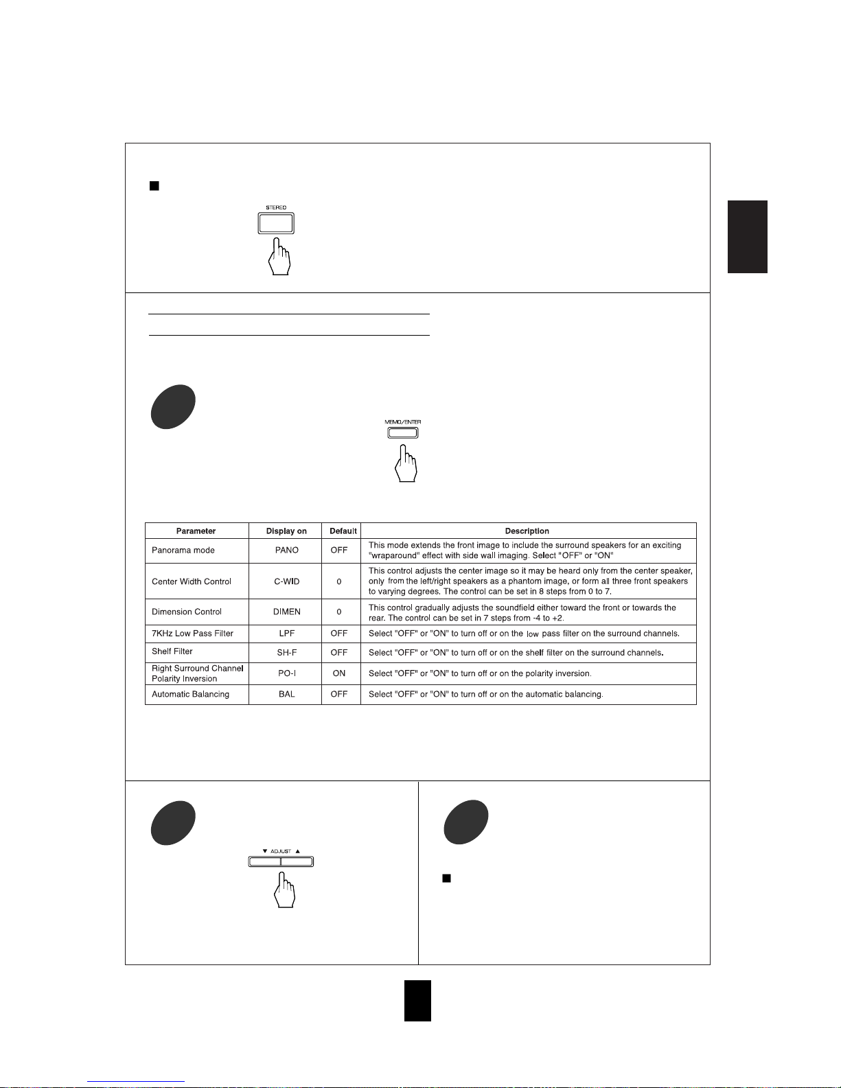
• If the parameter display disappears (after 5 seconds),
start from step three again.
Repeat steps three and four to adjust other
parameters.
5
Note:
• In Dolby Pro Logic II Custom mode, you may turn on
either 7 KHz Low Pass Filter or Shelf Filter, not both.
If so, the filter set previously is automatically
changed to OFF.
After selecting parameter with MEMO/ENTER
button, modify setting using ADJUST buttons.
4
15
When canceling the surround mode for stereo operation.
• Then the stereo mode is selected.
• To cancel the stereo mode, select the desired surround
mode using the DSP MODE button.
While scrolling “PL II MUSIC” (for Dolby Pro Logic II Music mode) or “PL II CUSTOM” (for Dolby
Pro Logic II Custom mode), press the MEMORY/ENTER button to select the desired parameter.
3
Adjusting the Dolby Pro Logic II parameters
• When selecting Dolby Pro Logic II Music and Custom modes, you can adjust the various surround parameters
for optimum surround effect.
• If the Dolby Pro Logic II Music or Custom display disappears (after 5 seconds), you cannot select the parameter.
In this case, select the desired surround mode again by pressing the DSP MODE button.
• In the Dolby Pro Logic II Music mode, you cannot select the 7 kHz Low Pass Filter, Shelf Filter, Right Surround
Channel Polarity Inversion and Automatic Balancing.
• Each time this button is pressed, the parameter changes and is displayed for five seconds as follows:

ENGLISH
16
Adjusting the speaker settings
Press the SPEAKER MODE button for
more than 2 seconds to enter the front-
center-rear speaker mode.
6
Select the desired speaker setting.
7
• The front-center-rear speaker setting is displayed.
• When the SPEAKER on/off switch is set to off, or
when the 6 CH DIRECT is selected as the input
source, the speaker mode button will not function.
• When in STEREO mode, the SPEAKER MODE
switch will only adjust the subwoofer setting.
• Adjust the settings of front, center, rear speakers and
subwoofer.
• If the speaker setting is adjusted to “S”, the low
frequency bass sound of the channel(s) is redirected to
the subwoofer or the front channels. If the speaker
setting is adjusted to "N" (for None), the sound of the
channel(s) is redirected to other channels.
• Each time this button is pressed, one of 11 different
speaker settings is selected and displayed for 8
seconds as follows;
(FS-CS-RS) (FS-CS-RN) (FS-CN-RS)
(FL-CS-RS) (FL-CL-RS) (FL-CL-RL)
(FL-CL-RN) (FL-CS-RL) (FL-CN-RL)
(FL-CS-RN) (FL-CN-RS)
• In the displays, F stands for Front, C for Center, R
for Rear, L for Large, S for Small and N for None.
• When judging whether a speaker is Large or Small,
please note that a standard large speaker can fully
reproduce sounds below 80 Hz.
• Some speaker settings are not available. For
example, Front: Small, Center: Large, Rear: Large
(FS-CL-RL) and any settings where BOTH center
and rear speakers are turned off.
Select the desired subwoofer setting.
9
• The desired speaker setting is memorized and then it
enters the subwoofer mode.
• If the speaker setting display disappears, start from
the above step 6 again.
• Each time this button is pressed, the subwoofer setting
changes and is displayed for 8 seconds as follows;
SUB W(oofer) - Y(es): When using a subwoofer.
SUB W(oofer) - N(o) : When not using a subwoofer.
• When the front speakers are set to “S”, the subwoofer
is automatically set to “Y”.
Memorize the desired speaker setting
while it is displayed.
8
• If the subwoofer setting display disappears, start
from the above step 6 again. • Each time this button is pressed briefly, the front-
center-rear speaker or subwoofer setting is displayed.
Memorize the subwoofer setting while it
is displayed.
10 Checking the speaker setting
Note: You do not need to adjust speaker and subwoofer
settings when using QS system speakers. Your
QS-AVR500 receiver speaker settings are preset
to all speakers as small (FS-CS-RS) and
subwoofer "Yes" for optimal sound quality and
ease of operaion with your QS speakers.

ENGLISH
17
Enter the test tone mode.
14
• The test tone is used to adjust each channel's level.
The test tone is not available for channels that are not
selected or not active. For example, in stereo mode,
the test tone function is not available for the rear
speakers.
Note: When the 6 CH DIRECT is selected as an input
source, the test tone function does not work.
At each channel, adjust the level as desired
until the sound level of each speaker is
heard to be equally loud.
15
Cancel the test tone function.
16
Adjusting each channel level
Adjusting each channel level with test
tone
Select the desired channel.
11
Adjust the level of the selected channel
as desired.
12
Repeat the above steps 11 and 12 to
adjust other channel levels.
13
• The LFE level can be adjusted within the range of 10
to 0 dB and other channel levels within the range of
-15 to +15 dB.
• In general, we recommend the LFE level to be
adjusted to 0 dB. (However, the recommended LFE
level for some early DTS software is -10 dB.) If the
recommended levels seems too high, lower the setting
as necessary.
• If the channel display disappears, start from the above
step 11 again.
• Each time this button is pressed, the corresponding
channel is selected and displayed for 3 seconds as
follows :
Front Left Center Front Right Rear Right
(Dolby Digital or DTS L(FE) )SubWoofer Rear Left
( ): Adjustable only when the digital signals from Dolby Digital or DTS
program source that includes LFE signal are input in the available
surround mode.
• When in Stereo mode, or the speaker setting is “N”,
center, rear or subwoofer channel will not be selected.
• The test tone will be heard from the speaker of each
channel for 2 seconds as follows;
Front Left Center Front Right
SUBwoofer Rear Left Rear Right
• When the speaker setting is “N”, the test tone of the
corresponding channel is not available.
• The test tone function is bypassed when the selected
decoding mode is not matched to the input signal format.
• You can select the desired channel and adjust its level
by repeating steps 11 and 12 in “Adjusting each
channel level” procedure.
ENGLISH
18
Adjusting delay times of speakers in
Dolby Digital, Dolby Pro Logic II or Dolby
Pro Logic Mode
• The delay time will be displayed for 5 seconds.
• The corresponding delay time is displayed. The
center delay time can be adjusted in the Dolby Digital
mode only.
• In case of Dolby Digital, Dolby Pro Logic II or Dolby
Pro Logic mode, when the distances from the prime
listening position to front left, center, front right, rear left
and rear right speakers are the same, the basic settings
are as follows according to the surround modes :
-In the Dolby Digital mode,
Center delay time : 0 ms, Rear delay time : 0 ms
-In the Dolby Pro Logic II Music, Matrix or Custom mode,
Rear delay time : 0 ms
-In the Dolby Pro Logic II Movie, Dolby Pro Logic mode,
Rear delay time : 10 ms
• If the center or the rear speakers are at a different
distance from the prime listening position than the front
speakers, the user can customize the delay settings to
make sure that the sound from all the speakers arrives at
the listening position at the same time. For every foot the
center or rear speakers are closer than the front speakers,
add 1 ms (one millisecond, or 1/1000 of a second) delay
to those speakers, to allow the sound the extra time to
travel to the listener to match the sound arrival time from
the main speakers (front left and front right). Sound
travels at roughly 1100 feet per second in air, but can be
estimated at 1000 feet per second to keep the math easy.
Downmixing into two front channels
• To cancel the 2-CH downmix mode, select the
desired surround mode by using the DSP MODE
button.
• When the playback of the source on the player is
stopped or interrupted, etc., the 2-CH downmix mode
is not canceled even though “ST” and the DTS or
Dolby Digital indicators go off.
• The receiver will automatically enter two channel
downmix mode if the headphones are plugged in and
the SPEAKER button is set to off, and digital
program material from DTS or Dolby is present. If
the headphones are unplugged and the SPEAKER
button is set to "on" in the 2-channel downmix mode,
the receiver will return to the previous mode.
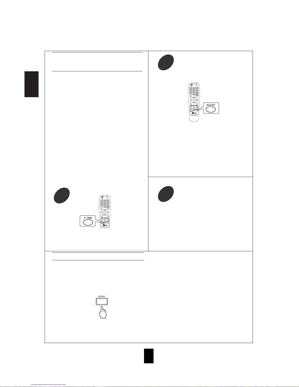
Check the delay time to be adjusted.
17 In Dolby Digital mode, repeat the above
steps, 17 and 18, to adjust the rear delay
time.
19
• Each time this button is pressed in the Dolby Digital,
Dolby Pro Logic II or Dolby Pro Logic mode, the
delay time changes in regular intervals.
• If the delay time disappears, start from step 17 again.
Adjust the delay time.
18
• Allows the multi-channel DTS or Dolby Digital signals
to be reproduced through only two speakers or through
headphones.
• When the digital signals from the DTS or Dolby Digital
program sources are input in available surround mode,
press the STEREO button.
• “ST” (for Stereo) and the DTS or Dolby Digital indicators
light up, meaning it enters the 2-CH downmix mode, and
then the discrete multi-channels (except LFE) are mixed
down into two front channels.

ENGLISH
19
LISTENING TO RADIO BROADCASTS
Presetting radio stations
Auto tuning
• Each time this button is pressed, the mode changes
as follows;
Tuning mode : “PRESET” goes off.
Preset mode : “PRESET” lights up.
• The tuner will now search until a station of sufficient
strength has been found. The display shows the tuned
frequency and “TUNED”.
• If the station found is not the desired one, simply
repeat this operation.
• Weak stations are skipped during auto tuning.
• Manual tuning is useful when you already know the frequency of
the desired station.
• Perform the steps 1 to 3 in “Auto tuning” procedure and press the
TUNING/PRESET UP( ) or DOWN( ) button repeatedly until
the right frequency has been reached.
• You can store up to 30 preferred stations in the
memory.
• “MEM” flickers for five seconds.
Manual tuning
• Each time this button is pressed, the band is changed
to FM or AM.
• When pressing the BAND button without selecting
the TUNER, the tuner will be selected automatically.
Select the tuner.
1
Select the tuning mode.
3
Select the desired band.
2
Press the TUNING/PRESET UP( ) or
DOWN( ) button for more than 0.5
second.
4
Tune in the desired station with auto or
manual tuning.
1
Press the MEMORY/ENTER button.
2
This manual suits for next models
3
Table of contents


