Snow Performance Diesel Stage 2 Boost Cooler User manual
© V. 0313, Snow Performance, Incorporated
INSTALLATION INSTRUCTIONS
Diesel Stage 2 Boost Cooler™
WATER-METHANOL INJECTION
SYSTEM
© V. 0313, Snow Performance, Inc
CAUTION
You must completely read through these instructions before
installing and operating this product. Failure to do so can
result in damage to this product and the vehicle.
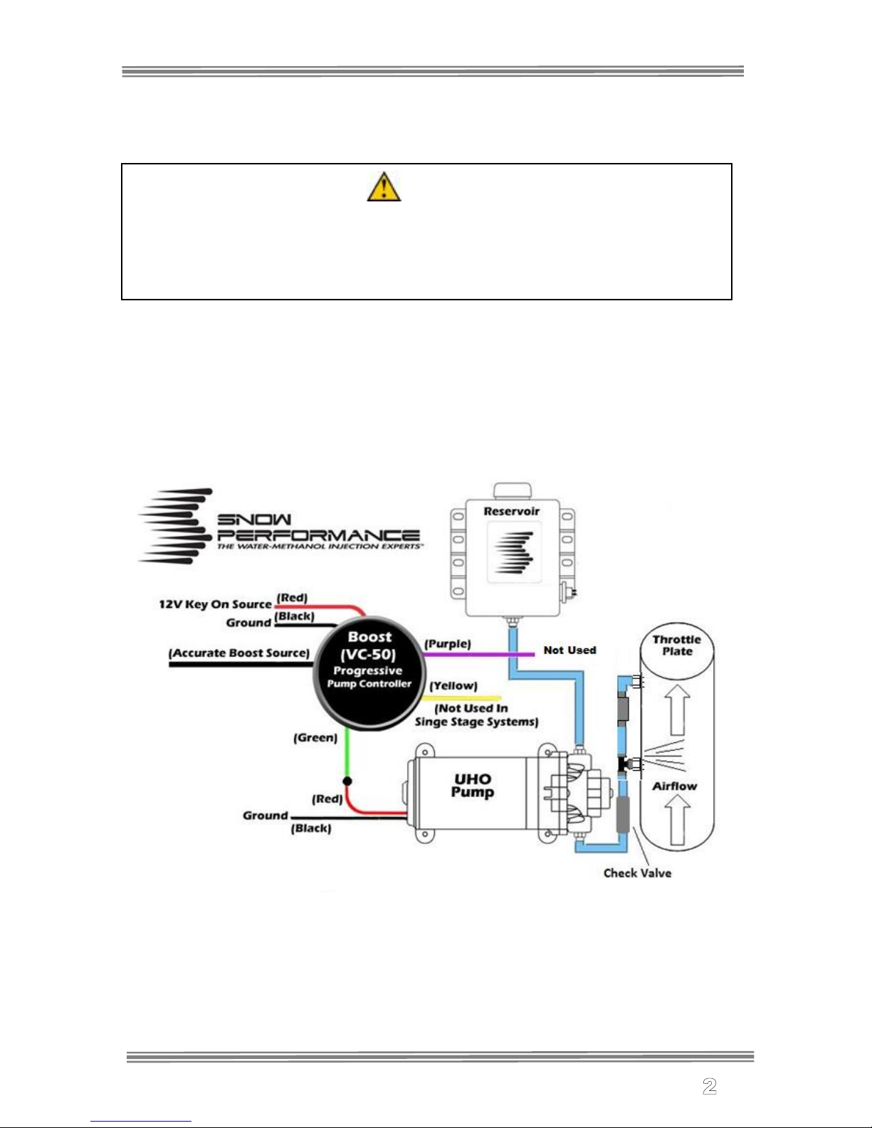
Wiring Diagram
© V. 0313, Snow Performance, Inc
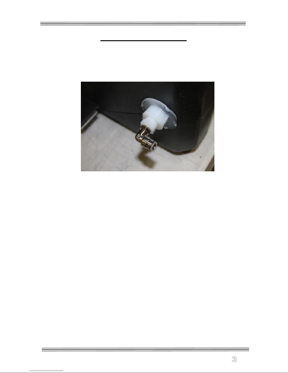
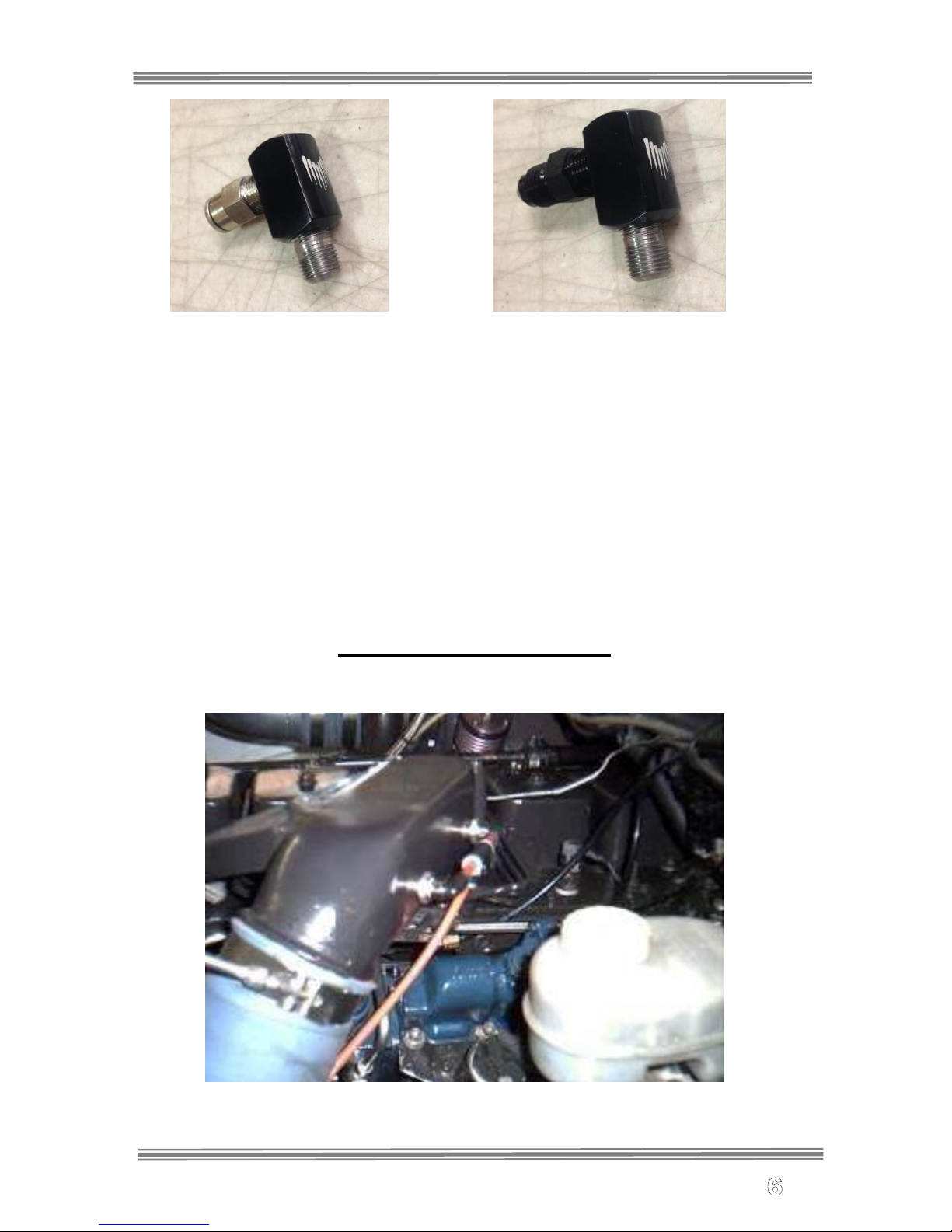
Reservoir Installation
•Install plastic reducer bushing and 90° quick connect fitting or
90° 4AN fitting into reservoir outlet. Use E6000® sealant on
threads.
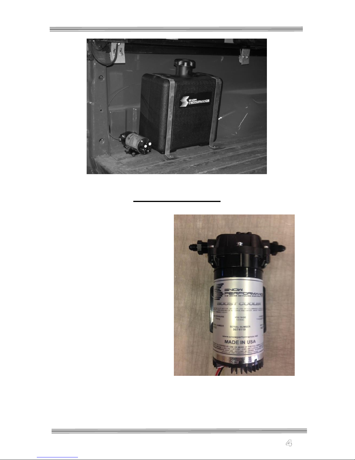
•Test fit reservoir in desired mounting location. Typical
placement is tucked up along the side of a pickup bed or in a bed
mounted tool box.
•Check the area under the bed near the desired mounting
location. Note the location of fuel tanks, fuel lines, and wiring.
•Mark the location of the four aluminum mounting strap tab bolt
holes.
•Drill through bed with appropriately sized drill bit. USE
CAUTION WHILE DRILLING.
•Mount reservoir with aluminum mounting straps using supplied
hardware.
© V. 0313, Snow Performance, Inc
Pump Installation
Braided Line Kits Only- Install
(2) 3/8” NPT to 4AN Straight
fittings into the pump inlet and
outlet using E6000® sealant on
the threads. Do not overtighten
as damage to the pump
housing can occur.
Quick Connect Kits Only-
Remove the blue rubber plugs
from the quick-connect fittings by
first pushing the plug toward the
pump, hold the grey collar
against the pump, and gently pull
the blue plug from the fitting.
Warning: Pulling against the
quick connects with excessive
force may cause fitting damage.
Step 1: Position the fluid pump so
that the inlet is positioned at or
below the lowest point of the reservoir, and within two feet of the
reservoir. (Pump can be installed in any orientation). This will ensure the
pump is primed with fluid for optimal flow and pressure to the nozzles.
**Arrows on the pump inlet and outlet indicate the direction of fluid
flow**

© V. 0313, Snow Performance, Inc
Step 2: Install the fluid pump with four (4) #8x1&1/2” screws and four (4)
#8 washers (supplied) in desired mounting location. Typical locations are
next to the tank in the bed or underneath the bed on frame rail.
Step 3: Fit the high temp nylon tubing or braided line between the tank
outlet fitting and the pump inlet, ensuring there are no kinks in the line
and there is no stress on the fittings. Sharp kinks/bends can cause a leak
in the system.
Braided Line Kits Only- Using the 1’stainless braided line section
supplied in the kit connect the tank outlet to solenoid inlet.
Quick Connect Kits Only- Once high temp nylon is measured from tank
outlet to pump inlet cut tubing using razor blade. Remove any burrs so
that the fluid line properly seals against the internal o-rings inside the
quick connect fittings. Insert tubing into the quick connects until fully
seated, and pull lightly against quick connects to ensure proper
installation between tank outlet to pump inlet
Nozzle Installation
Nozzle sizing is a function of horsepower, which approximates the
engine airflow, and boost, which approximates intake charge heat.
Recommended starting points:
HP
Nozzle 1
Nozzle 2
350 > WHP
175 ml/min
375 ml/min
400 - 500 WHP
175 ml/min
625 m/min
500 < WHP
375 ml/min
625 ml/min
Nozzle Identification:
The nozzles are stamped with the following identification stamps
on the side of the nozzle body:
Nozzle Stamp
Nozzle Size
Nozzle Stamp
Nozzle Size
1
60 ml/min
4
225 ml/min
2
100 ml/min
5
375 ml/min
3
175 ml/min
6
625 ml/min
Assemble desired nozzle into nozzle holder using E6000® sealant. The
end of the nozzle with the fine mesh screen is to be inserted into
the nozzle holder. Torque 1/2 turn past finger tight. Do not use Teflon
sealants on Snow Performance fittings.
© V. 0313, Snow Performance, Inc
Correct Correct
The nozzle is mounted using its external 1/8 NPT threads. Tighten the
nozzle and nozzle holder assembly one half turn past finger tight using
E6000® sealant to seal the threads. Note that the nozzles can be
mounted almost anywhere at or before the inlet to the intake. They must
be located after the turbo and intercooler however. Ideal locations are
usually immediately before the intake itself on the tube coming from the
intercooler outlet. Ensure that the nozzle has a clear spray pattern into
the airflow, and that the tip of the nozzle is flush with the inner wall of the
pipe or protruding slightly into the airflow.
Dodge Applications:
5.9L Cummins:
© V. 0313, Snow Performance, Inc
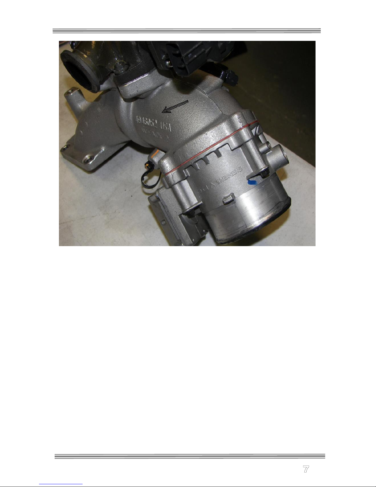
6.7L Cummins:
Nozzles are mounted in the cast intake elbow located on the
driver’s side of the engine. This elbow houses the EGR
valve, EGR throttle plate, and the MAP sensor.
Recommended location is after the EGR throttle plate –
indicated by arrow in photo.
Tip: It is recommended that the cast elbow be removed
before drilling and tapping.
Tip: Mount nozzles in the middle of the elbow on the front
side approx 3” apart so spray is 90º to airflow.
Tip: To make sure there is no pooling of fluid while injecting,
make sure nozzle tip is at least flush with the inside of the
elbow when tightened.
© V. 0313, Snow Performance, Inc
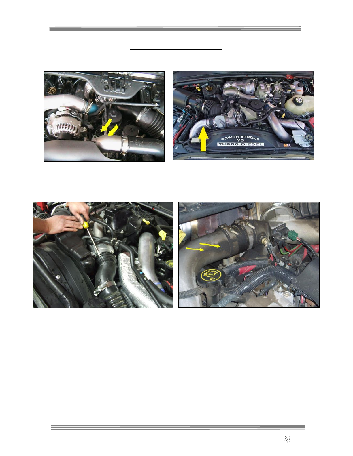
Ford Applications:
6.0L Powerstroke: 6.4L Powerstroke:
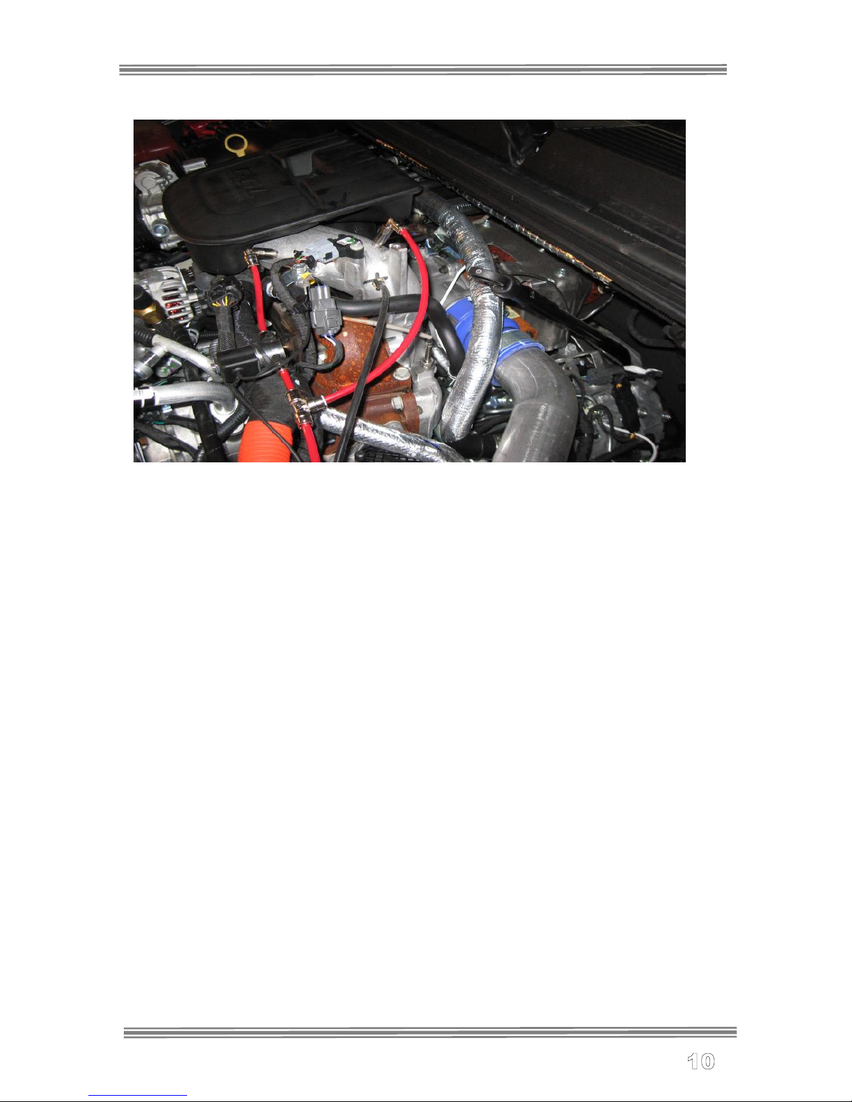
6.7L Powerstroke: 7.3L Powerstroke

© V. 0313, Snow Performance, Inc
GM Applications:
2004-2007 LB7, LLY, LBZ
2007-10 LMM
© V. 0313, Snow Performance, Inc
2011-Up LML
© V. 0313, Snow Performance, Inc
Nozzle/Solenoid/Check Valve (Quick Connect Kits)
Solenoids are flow directional. Be sure to note which port is the
INLET/PRESSURE port (2 or IN) and which is the OUTLET port (1 or
OUT).
The main outlet line coming from the Reservoir connects to the
solenoids inlet. The outlet of this solenoid connects to the inlet of
the pump. The outlet of the pump connects to the Check Valve Inlet.
The Check Valve Outlet connects to the Union “T” and then both
nozzles.
Measure the distance from the pump outlet to the injection location. Cut
the ¼” red tubing using utility knife. Make cuts as square as possible.
Ensure there are no kinks in the tubing and insert tubing into quick
disconnects until fully seated. Gently pull on tubing to ensure a good
connection. Use tie wraps to help route tubing and to ensure it doesn't
contact moving or hot parts in the engine compartment.
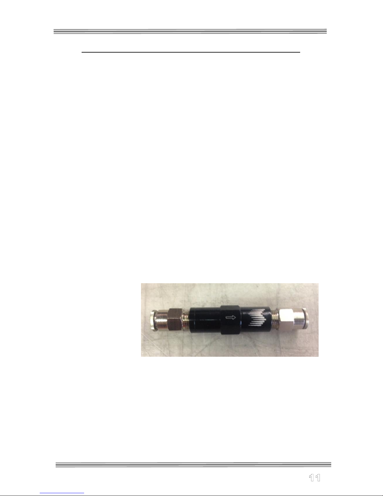
The check valve assembly will ensure that boost pressure does not
back-feed air into the system or siphon due to engine vacuum. Ensure
the check valve is installed with the arrow pointing in the direction of flow.
The Check valve will be installed between the pump outlet and T fitting.
Install check valve as close to T fitting as possible.
Quick Connect
Kits Only- Fit the
NPT thread to push
connect adapters in
both sides of the
check valve using
E-6000 sealant on
the threads. Press
the high pressure
tubing in each fitting, ensuring the check valve is oriented properly in the
direction of flow.
© V. 0313, Snow Performance, Inc
Nozzle and Solenoid Connection (Braided Line Kits)
Solenoid is flow directional. The solenoid is designed to be installed
between the 7 gallon and pump inlet. Before installing on vehicle remove
all NPT threaded fittings and install E6000 sealant on threads / re install.
Use supplied self-tapping screws/washers to install in desired location.
The solenoid outlet connects to the pump inlet via a 1’ section. The
pump outlet connects to the 20’ section of braided line and then to
the check valve inlet. The rest of the system will be plumbed using
the 1’ sections.
Installation- Electrical
Step 1 Variable Controller Installation
•Mount controller in desired location using a 52mm gauge
pod.
•Connect vacuum/boost hose (black silicon hose included in
kit) to tubing coming from the controller to an accurate
boost source using included brass hose barb fitting and
supplied 1/8” boost line. Secure connections with tie wraps.
CAUTION: Disconnect the negative battery terminal while
connecting wires to prevent electrical fire or damage to controller.
•Connect BLACK wire to good ground location.
•Connect GREEN wire to Pump RED power wire.
•Connect RED wire to 12Volt key on source.
•YELLOW wire is not used.
•Purple wire is not used
***Caution***
Do not route wires near hot or moving parts. Use corrugated wire
loom and tie wraps to protect and route wires.
© V. 0313, Snow Performance, Inc
Always have a good electrical ground connection.
Poor ground will result in erratic operation of
controller.
Variable Controller Settings/Screens/Functions
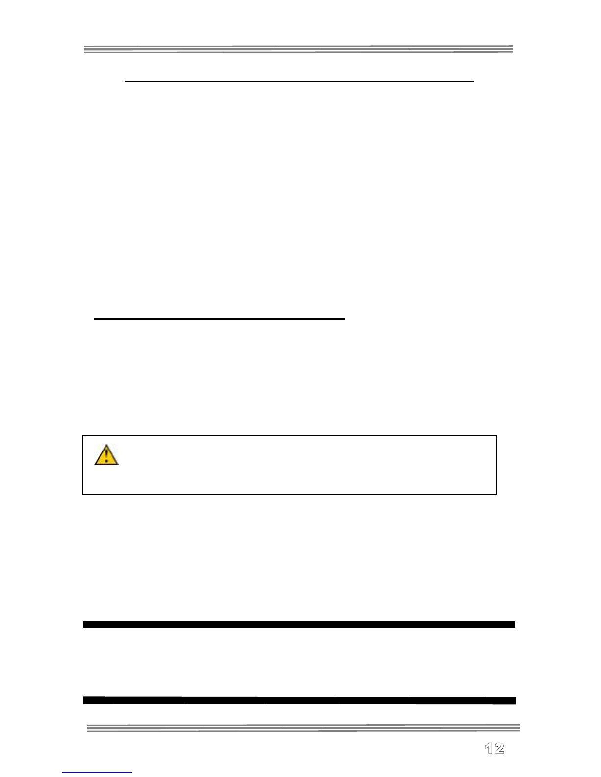
Main Screen
•Main Screen (see right) is used to monitor
boost pressure, injection, second stage
activation, and to prime the system.
•To prime the system press the red
button underneath “P”. This will
command 100% injection briefly to fully
prime the system. ONLY ENGAGE
PRIME WHEN ENGINE IS RUNNING!
•Boost pressure is displayed in PSI on the upper left of the screen
•Percentage of Injection is displayed using the graph in the
middle of the screen. When injection is turned “Off” the graph will
display the text “Off”.
•(Dual Stage Systems Only) When a second stage of water-
methanol is activated a asterisk will appear where “PSI” is
located alerting the user or both stages injecting.
•To enter the setting screens press the red button directly
under the arrow on the bottom right.
CAUTION: Do not operate the prime button when the engine is
not running. Only engage priming of the system when the engine is
on.
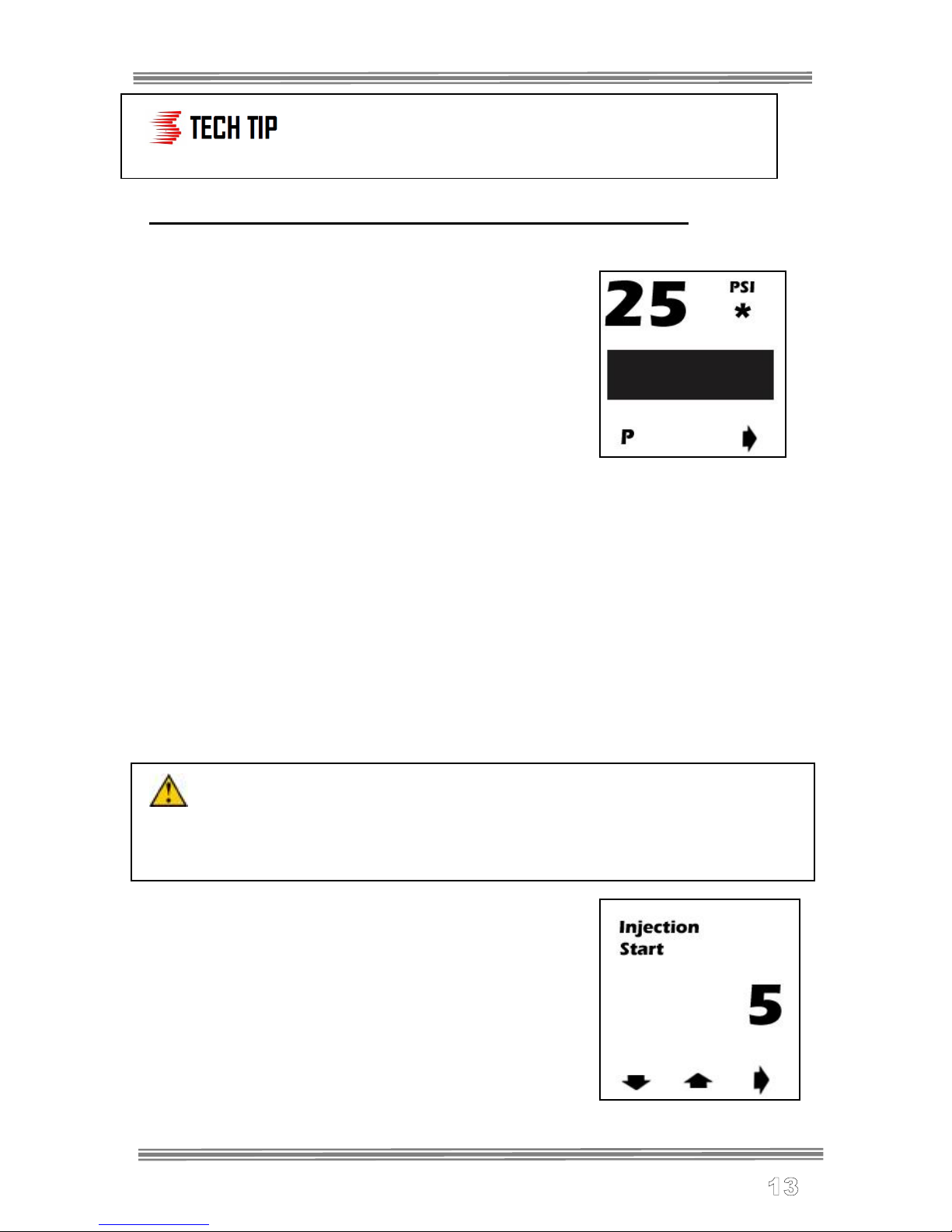
Injection Start
•Setting screen 1 (see right) is used to select
what boost pressure will start injection. This
should be set 3psi above your vehicle’s
unloaded flat land cruising boost using the
red buttons below the up and down arrows
to adjust the PSI to desired setting. Press
the red button underneath the arrow
pointing right to move to setting screen 2.
© V. 0313, Snow Performance, Inc
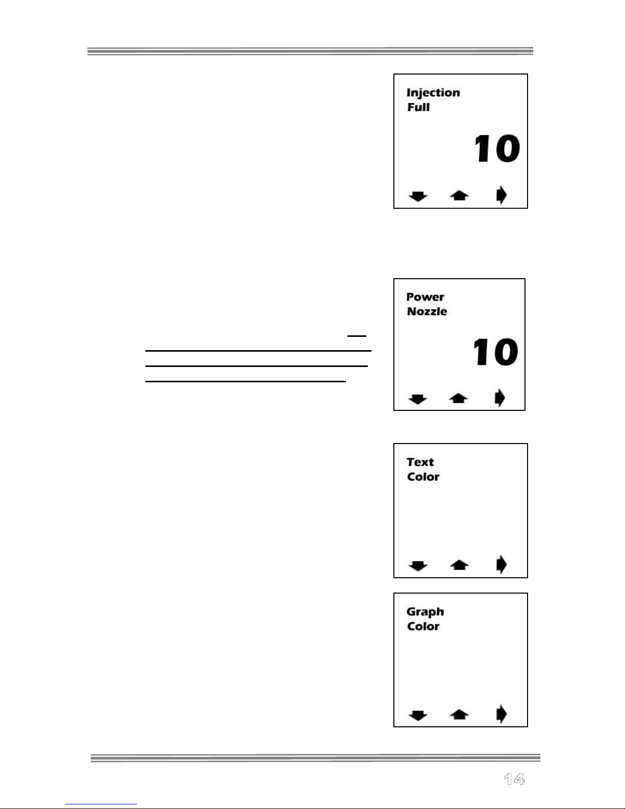
Max Injection
•Setting screen 2 (see right) is used to select
what boost pressure will correlate to max
injection. This should be set the vehicles
maximum boost level using the red buttons
below the up and down arrows to adjust the
psi to desired setting. Press the red button
underneath the arrow pointing right to move
to setting screen 3.
Power Nozzle
•Setting screen 3 (see right) is used to
select what boost pressure a second
stage of injection will be triggered. If a
dual stage system is not being used
this must be set above 50 psi to the
“off” setting to avoid fault code.
Press the red button underneath the
arrow pointing right to move to setting
screen 4.
Text Color
•Setting screen 4 (see right) is used to select
what text color will be displayed on screen.
Using the red buttons below the up and
down arrows adjust the color to the desired
setting (Red, Blue, Green, Yellow, Orange,
Purple, White) available. Press the red
button underneath the arrow pointing right to
move to setting screen 5.
Graph Color
•Setting screen 5 (see right) is used to
select what Graph color will be
displayed on screen. Using the red
buttons below the up and down arrows
adjust the color to the desired setting
(Red, Blue, Green, Yellow, Orange,
Purple, White) available. Press the red
button underneath the arrow pointing
right to move to setting screen 6.
© V. 0313, Snow Performance, Inc
Injection On/Off
•Setting screen 6 (see right) is used to toggle
between on/off mode. In on mode injection
will take place based off the boost settings
in the unit. In off mode no injection will take
place and the “off” icon will be shown on the
main screen. In this mode the controller will
only function as a boost gauge.
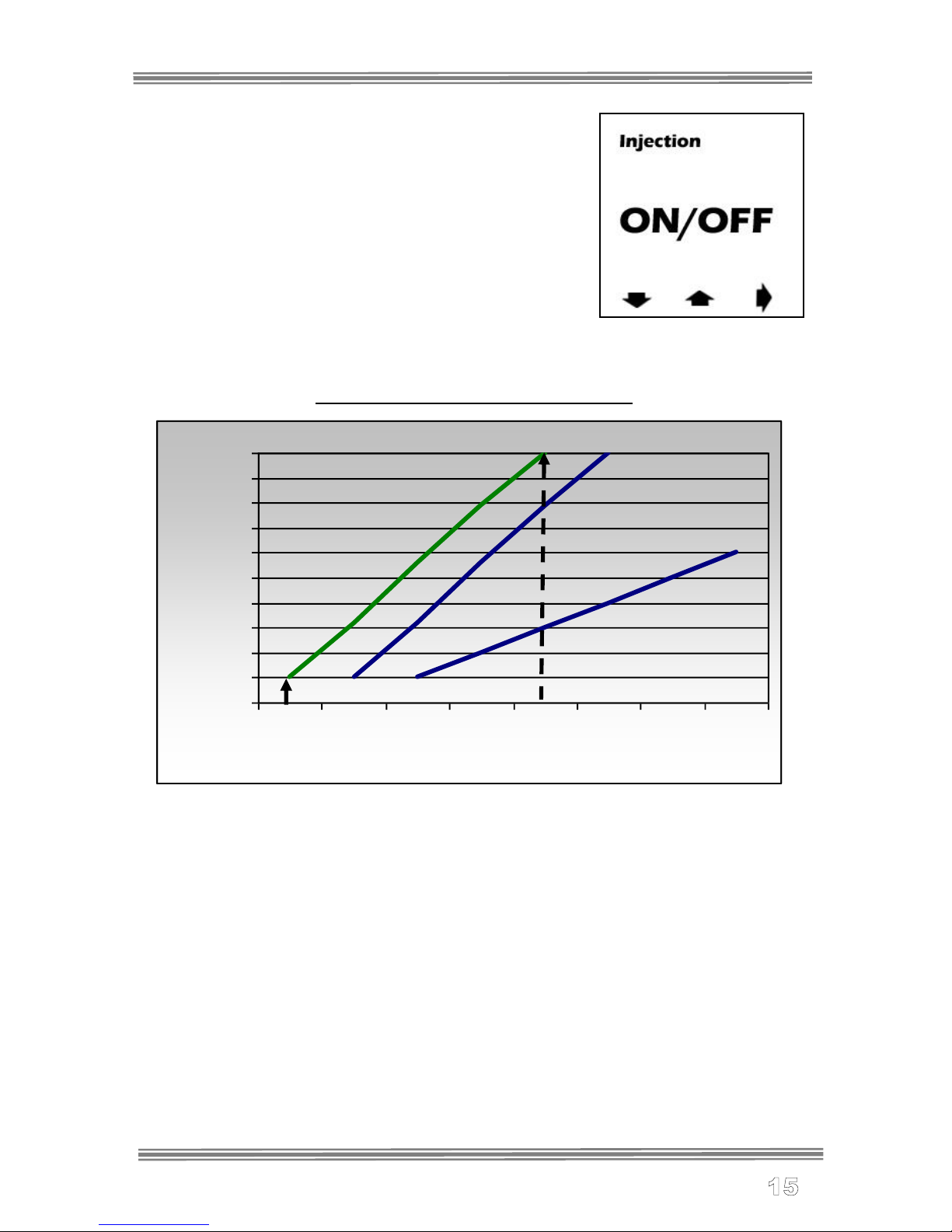
Controller Operation Example
For the middle line, the chart shows the Start dial at 6 psi and the
Full dial at 13 psi. At 6 psig of boost pressure the pump will
operate at 10%. At 13 psig of boost pressure, the pump will
deliver 100% of injection pressure. For boost pressure readings
between the Start and Full settings, the controller will linearly
adjust the pump pressure as shown on the graph.
0
10
20
30
40
50
60
70
80
90
100
4 6 8 10 12 14 16 18
Boost Pressure psi
Start
Pump Output %
Full

© V. 0313, Snow Performance, Inc
Other Controller Functions
Fail Safe Alerts
Clogged Line
•In the event of a clogged line the psi reading on the main screen
will turn to stars and begin flashing. If this occurs, fix the problem
and press the middle red button to clear the code.
Broken Line
•In the event of a broken line the psi reading on the main screen
will turn to stars and begin flashing. If this occurs, fix the problem
and press the middle red button to clear the code.
Solenoid Not Engaging (Dual Stage Systems Only)
•In the event of a solenoid not opening to engage a second stage
of water-methanol the psi reading on the main screen will turn to
stars and begin flashing. If this occurs, fix the problem and press
the middle red button to clear the code.
Testing the System
Step 1 Priming The System
**Before operating the system, it is recommended that the lines are
first primed with fluid and the spray pattern checked**
•Fill reservoir with water
•Remove the nozzle from the
intake tube.
•With the nozzle temporarily
placed inside an empty container,
purge the system by pushing the
“prime” button (left hand button)
on the controller until fluid flows
consistently through the nozzle.
**If pump goes on and fluid level doesn't go down, there is an
obstruction in the tube or nozzle.**
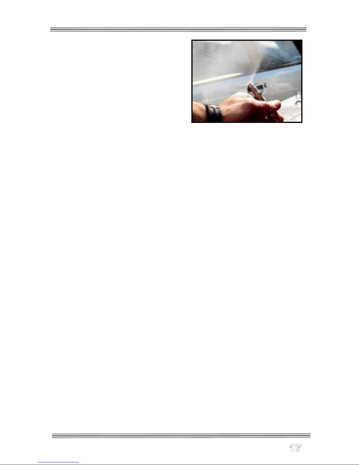
© V. 0313, Snow Performance, Inc
** Spray pattern should be 120º and
a fine mist. See photo.
**If the pump fails to activate,
check power and ground wiring**
Maintenance
Remove nozzle(s) and clean screen filters once per year using a
calcium removing formula such as CLR®
The Boost Cooler® has been designed to operate with high
concentrations of methanol. Oil or other additives are not required
for system lubrication, and can cause damage to the system.
Contaminants in the fluid such as dirt can damage the system.
Ensure that dirt and debris do not fall into the tank.
Do not use Teflon tape or paste to seal connections. These sealers
are not as effective as the Goop sealant provided and can break
down over time, clogging components.

© V. 0313, Snow Performance, Inc
Disclaimer
Do not use this product until you have carefully read the following agreement.
This sets forth the terms and conditions for the use of this product. The installation of this
product indicates that the BUYER has read
and understands this agreement and accepts its terms and conditions.
Performance products by their nature are designed to increase horsepower and
performance not engineered in the original vehicle and the increased stress could result in
damage to related systems. This is a high performance product –use at your own risk.
Snow Performance Inc., Its agents, employees or owners shall not be under any liability
whether in contract or otherwise whether or not resulting from our negligence or contents of
information supplied for any damage or loss resulting from such information.
The BUYER is responsible to fully understand the capability and limitations of his/her
vehicle according to manufacturer specifications
and agrees to hold the SELLER harmless from any damage resulting from failure to adhere
to such specifications.
The SELLER disclaims any warranty and expressly disclaims any liability for personal
injury or damages. The BUYER acknowledges
and agrees that the disclaimer of any liability for personal injury is a material term for this
agreement and the BUYER agrees to
indemnify the SELLER and to hold the SELLER harmless from any claim related to the
item of the equipment purchased. Under no
circumstances will the SELLER be liable for any damages or expenses by reason of use or
sale of any such equipment.
The BUYER is responsible to obey all applicable federal, state, and local laws, statutes,
and ordinances when operating his/her
vehicle, and the BUYER agrees to hold SELLER harmless from any violation thereof.
The SELLER assumes no liability regarding the improper installation or misapplication of its
products.
It is the installer's responsibility to check for proper installation and if in doubt, contact the
manufacturer.
Warranty
Snow Performance 1-Year Warranty Policy:
Snow Performance, Inc. warrants that the Product shall conform to and perform in
accordance with published technical specifications and shall be free of defects in materials
and workmanship for 1-year providing:
1. You are the original purchaser and provide proof of purchase.
2. The system was purchased from a Snow Performance Authorized Dealer at MRP pricing
set by Snow Performance.*
*No warranty will be offered for any Snow Performance products if purchased below
MRP. For MRP pricing of your product check www.snowperformance.net.
3. An RMA # has been attained and is displayed on package containing returned part.
4. Parts Warranty ~ 90 day warranty on parts purchased separately if used in conjunction
with a Snow System. No warranty implied if used with a non-Snow part/system. Subject to
Snow’s inspection of the product, Snow will remedy defects in materials and/or
workmanship by repairing or replacing, at Snow’s option, the defective product without
charge for parts or labor, subject to the limitations and exclusions described in this
warranty.
This warranty does not cover problems caused by normal wear and tear including aesthetic
oxidation of surfaces, accidents, unlawful vehicle operation, or modifications or repairs to

© V. 0313, Snow Performance, Inc
product not performed or authorized by Snow. This includes any product that is
disassembled or taken apart for any reason.
In addition, this warranty does not cover problems resulting from conditions beyond Snow’s
control including, but not limited to, theft, misuse, overloading, or failure to assemble,
mount or use the product in accordance with Snow’s written instructions or guidelines
included with the product or made available to the original retail purchaser. In the event of
failure, Snow will repair or replace the part at Snow's sole discretion. Failures resulting from
misapplication or misuse of the Product, failure to adhere to any specifications or
instructions, or failure resulting from neglect, abuse, accidents, or act of nature are not
covered under this warranty.
Warranty service may be obtained by emailing tech@snowperformance.net with a copy of
your purchase invoice for the product, getting an RMA (Return Merchandise Authorization)
number, and delivering the part to Snow. Customer agrees to insure the Product or assume
the risk of loss or damage in transit, to prepay shipping charges to Snow, and to use the
original shipping container or equivalent. Shipping for Warranty replacement parts shipped
outside the continental US will be charged to customer.
Non-Warranty Repair/Retest
Products returned due to damage or misuse and Products retested with no problem found
are subject to repair/retest charges. Product will be returned to customer at customer’s
expense. A credit card number must be provided in order to obtain an RMA (Return
Merchandise Authorization) number prior to returning Product.
Distributor/Dealer Warranty:
All customers/dealers must deal directly with Snow Performance to receive warranty. No
warranty will be issued through a distributor for any reason.
Return Policy:
All returns must be called in for RMA #. Snow Performance will not take used kits or parts
for refund. If you are returning an unused kit there is a 15% restocking fee minus
shipping/handling. All returns must be made within 30 days of purchase date. No
exceptions.
LIMITATION OF LIABILITY: REPAIR OR REPLACEMENT OF A DEFECTIVE PRODUCT
IS THE ORIGINAL RETAIL PURCHASER’S EXCLUSIVE REMEDY UNDER THIS
WARRANTY. DAMAGE OR INJURY TO THE ORIGINAL RETAIL PURCHASER, TO HIS
OR HER VEHICLE, CARGO, OR PROPERTY, AND/OR TO ANY OTHER PERSON OR
PROPERTY IS NOT COVERED BY THIS WARRANTY. THIS WARRANTY IS
EXPRESSLY MADE IN LIEU OF ANY AND ALL OTHER EXPRESS WA RRANTIES,
WHETHER ORAL OR WRITTEN. SNOW’S SOLE LIABILITY IS LIMITED TO THE
REMEDY SET FORTH ABOVE. IN NO EVENT WILL SNOW BE LIABLE FOR ANY
DIRECT, INDIRECT, CONSEQUENTIAL, INCIDENTAL, SPECIAL, EXEMPLARY, OR
PUNITIVE DAMAGES OR FOR ANY OTHER DAMAGES OF ANY KIND OR NATURE
(INCLUDING, BUT NOT LIMITED TO, LOST PROFITS OR LOST SALES). SOME
STATES DO NOT ALLOW THE EXCLUSION OR LIMITATION OF INCIDENTAL OR
CONSEQUENTIAL DAMAGES, SO THE ABOVE LIMITATIONS MAY NOT APPLY TO
YOU.
Non-Warranty Repair/Retest
Products returned due to damage or misuse and Products retested with no problem found
are subject to repair/retest charges. Product will be returned to customer at customer’s
expense. A credit card number must be provided in order to obtain an RMA (Return
Merchandise Authorization) number prior to returning Product.

© V. 0313, Snow Performance, Inc
Notes
The contents of this document are subject to change without prior notice.
No part of or this entire document may be reproduced in any form
without prior written permission of Snow Performance, Inc under the
copyright except for private use.
Table of contents
Popular Engine manuals by other brands

Hiwin
Hiwin TMRW13 Assembly instruction

Lenze
Lenze M Series Mounting instructions

Interroll
Interroll RollerDrive BT100 user manual

GEIGER
GEIGER SOLIDline GJ56 Series Original installation and operating instructions

Tecumseh
Tecumseh OHV140 Operator's manual

O.S. engine
O.S. engine FS-30S Owner's instruction manual


