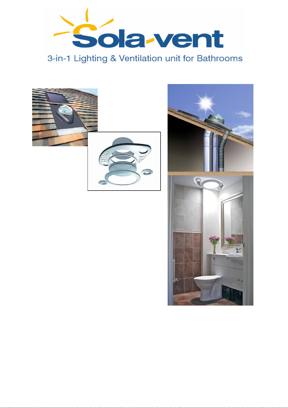
SOLaVent 230 User manual
230 Sola-Vent System Dec 2006
Components
SunPipe Components
1 x 230 SunPipe Diamond Dome
1 x Integral ABS Flashing Plate with Extract Duct
1 x Code 4 lead skirt
1 x SunPipe Extension 610mm Length – Crimped End
1 x SunPipe 30° or 45° Adjustable Elbow
1 x SunPipe Standard 610mm Length - Plain End
1 x SunPipe 250mm Long Bell End Ceiling Extension
1 x SunPipe Ceiling Trim
1 x SunPipe Ceiling Bezel
1 x Silicone Sealant
1 x SunPipe Installation Pack
Sola-Vent Components
1 x Photovoltaic Flashing Plate c/w polycrystalline PV panel
1 x Code 4 lead skirt 2 x 35W Halogen Bulbs
1 x Extract Fan and Housing 2 x Shower Downlighters
1 x Length of Flexible Ducting 1 x Sola-Vent Plywood Backing Plate
2 x Jubilee Clips 1 x Sola-Vent Ceiling Fascia c/w PIR
2 x 400mm Length of White PVC Duct 2 x 30Amp 240v Junction Box
1 x Black connecting adaptor to suit White PVC Duct 1 x Sola-Vent Installation Pack
1 x Sola-Vent Base Unit 1 x Mains back up facility
2 x 12v Batteries
1 x Black transition to suit Sirroco Fascia
Installation instructions: Monodraught Sola-vent
(All mains wiring should be carried out by a qualified electrician.)

DO NOT Connect the internal batteries until the installation has been fully
completed. Failure to do so may cause damage to the system.
1. Check to ensure that there is sufficient room for the ventilation ductwork and
SunPipe lengths between the bathroom ceiling and the selected position of the
roof flashing and that a suitable mains lighting circuit is available to the
bathroom ceiling for the Halogen downlights, connected to the bathroom light
switch and a mains plug socket is available in the loft / ceiling void for the
mains buck up facility.
2. Check to ensure that there is a suitable area of pitched roof of between 15º and
60º elevation, facing between Southwest and Southeast, to which the solar
panel can be mounted. This should not have any overshadowing from trees or
nearby buildings. The solar panel can be located up to 9m away from the Base
Unit with additional extension cables available from Monodraught and does not
need to be located on the same roof orientation as the SunPipe system.
3. Having disconnected the mains electricity
supply, remove any previous electric light
fittings if necessary at this stage. Cut a hole in
the bathroom ceiling at your chosen central
position. Use a drill to centre the position of
the opening between the ceiling trimmers.
Finally use the plywood plate as a template to
mark out the three ceiling openings required.
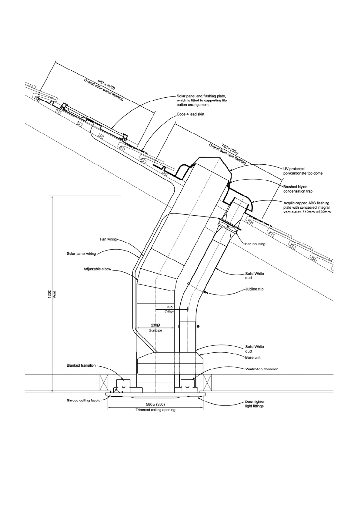
4. Fit the roof flashings and Sunpipe system as per
the Sunpipe standard instructions, aligning the
lower end of the pipe with the ceiling opening.
As shown in the image.
5. Solar panel mounting
a. The solar panel should always be
mounted on the south-facing roof and
can be fitted above or below the Sola-

Vent flashing and up to 9m away from the Base unit. (Additional
extension cables are available from Monodraught tel 01494 897700)
b. Fit the solar panel flashing plate as per the SunPipe standard flashing
plate installation instructions.
c. The cable should be passed through the roofing felt by making a small
hole through it.
d. Secure the cable internally by taping it to the SunPipe system using the
silver tape supplied with the SunPipe.
6. Place the plywood plate between the rafters above
the ceiling and align it with the previously cut
holes. It may be necessary to remove any loft
insulation to fit the plywood plate and add
additional support trimmers.
7. Fit the ceiling fascia to the ceiling from below,
securing it through the ceiling and into the
plywood backing plate by drilling four small holes
equally spaced around the central ring and fix
using the screws supplied, being careful not to
over tighten the screws.
8. Fit the black ceiling trim ring to the fascia using
the self tapping screws. Insert the bell end,
aligning it with the lower end of the Sunpipe and
insert it through the ceiling fascia and around the
Sunpipe.
9. Fix the Sunpipe diffuser by pressing it up into the ceiling trim ring and turning
the tabs to lock the diffuser in place. The trim may then be fixed to the ceiling
trim by aligning the tabs, pressing firmly.
10.Seal the Bell end extension length from above
using the silver tape.
11.Insert the cast metal holders for the downlighter units into the ceiling fascia,
ensure that the securing clips are securely located. Fit the bulbs and retaining
clips as per the manufacturer’s instructions.
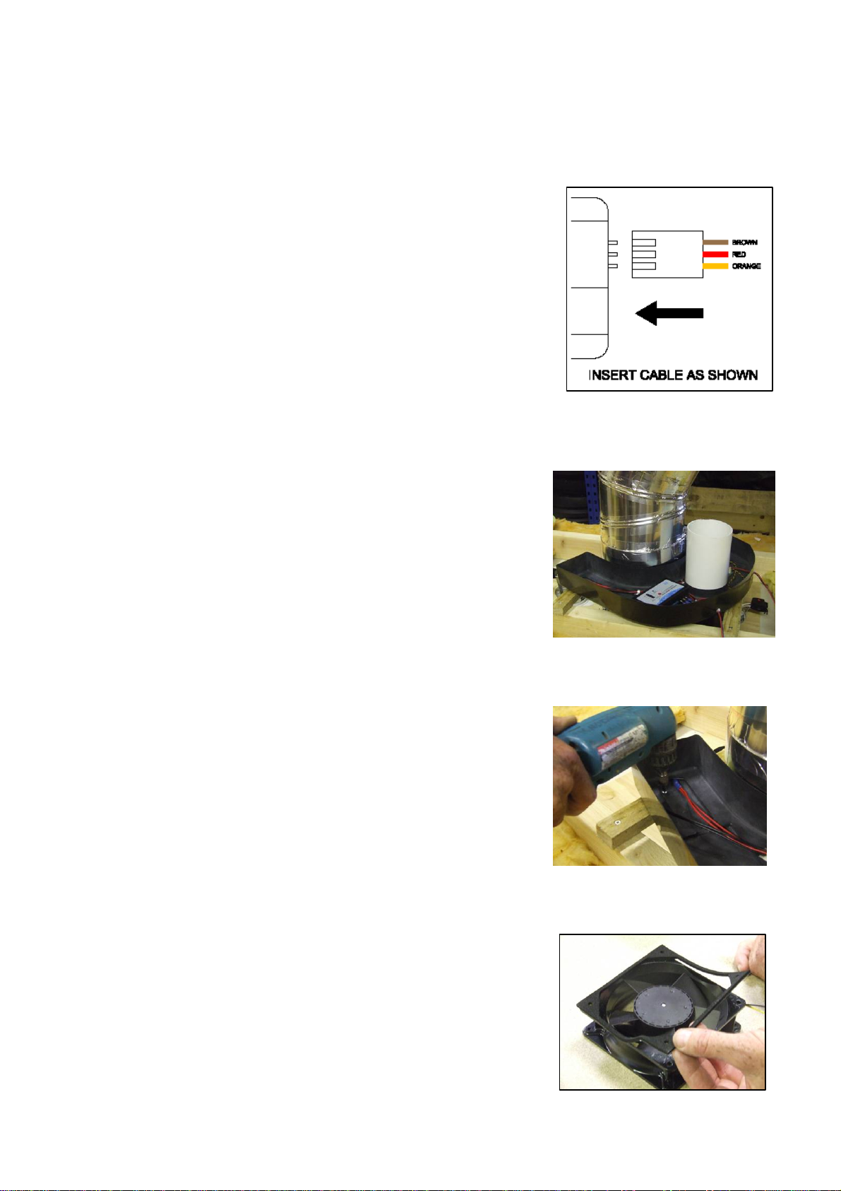
12.Connect the Miniature PIR using the three core cable
provided. If a male to female connector is included
this will be a simple push fit to join together. One
cable will be already fitted to the fascia and one to
the base unit. If there is not a male to female
connector, make sure that the connector is fitted
correctly aligned as per the colour diagram on the
rear of the Ceiling fascia.
13.From above, fit the Sola-vent Base component by
carefully matching up the lower end of the fan
housing with the upward facing duct fitted to the
ceiling fascia. It will be necessary to use additional
support trimmers above the ceiling rafters to
support the Base Unit. (White duct illustrates the
position of the upward facing duct)
14.Secure to the rafters through the black ABS where
possible using the screws supplied. Use a minimum
of three fixings for stability.
15.Fit the foam gaskets to the fan ensuring that the
seal does not interfere with the blades.

16.Position the fan in place within the fan housing below the Sola-Vent flashing
plate. Take note of the direction arrows on the side (Arrow should point towards
roof) and check that the fan spins freely without any obstruction from the foam
gasket.
17.Secure to the housing fitted to the underside of
the roof unit using the nuts and bolts supplied. If
there are any gaps between the two plates these
can be taped together using the silver tape
supplied with the Sunpipe system to ensure a
tight seal.
18.Connect the 400mm long White PVC ducts to the upward facing duct , see item
13 and the remaining duct to the bottom of the fan housing, see the detailed
drawing at the start. The ducts can be cut to suit the length required or jointed
together using the black jointing piece enclosed. Seal the joints with the silver
SunPipe tape.
19.Secure the lower end of the flexible duct to the
lower white duct and the upper end to the upper
white duct the jubilee clips. The flexible duct
should be a tight fit between the White PVC
ducts. If required, it may be necessary to
shorten the flexible duct and/or shorten the
White PVC ducts.
20.Connect the cables from solar panel and the fan to
the spur cables from the base unit using the clear
plastic connectors. There is coloured heat shrink
fitted to the cables to identify which cable serves
which item. Yellow is to be connected to the Solar
Panel. Blue is to be connected to the Fan. If the
cables are not long enough additional extension
cables are available.

21.Having checked that the electricity supply is disconnected, connect the mains
wiring to the Downlighters from the switched mains lighting circuit using the
two brown connector blocks supplied. Ensure that no bare wire is showing and
insulate with electricians tape if necessary. (All mains wiring should be
carried out by a qualified electrician.)
22.Having checked all wiring connections for safety reconnect the mains supply
and test the mains lights using the bathroom light switch.
23.Connection of the mains back up facility should be carried out prior to the
connection of the batteries. This should be plugged into the mains socket using
the mains adaptor supplied. This connection must be carried out within the loft
space / ceiling void.
24.Having ensured that the fan, solar panel and PIR are connected, remove the
Base Unit lid and fit and connect the 12V batteries. Carefully connect that
batteries ensuring that the red terminal of the battery is fitted to the red cable
and the black terminal is fitted to the black cable.
25.Refit the lid to the Base Unit. This can be held in position using silver tape if
required.
26.Secure any loose wiring (where applicable) in the roof space using cable ties
and/or cable clips.
27.Having checked all wiring connections for safety test the mains lights using the
bathroom light switch. The PIR takes 30 seconds to become active following
connection of the batteries. A period of movement (four seconds of continuous
movement) within the bathroom should result in the triggering of the PIR unit
and after a short delay the fan ventilator will be activated and run for 15
minutes.

Maintenance instructions: Monodraught Sola-vent
The Monodraught Sola-vent is designed to run with little or no maintenance
for years of trouble-free service.
The Sola-vent has a number of non-serviceable components in the ABS
base unit and these may be replaced by a qualified electrician if
necessary. The solar batteries, have a five year life expectancy and you
will be automatically contacted when these are due for renewal.
Occasional cleaning of the ceiling fascia and diffuser may be carried out
with a damp cloth.
The extract ducts can be cleaned by passing a vacuum cleaner over the
air intake grilles.
Bulb replacement can be carried out by removing the glass/circular
retaining clip from below.
The bulbs can then be disconnected from the connectors above and
replaced.
The PIR unit can be cleaned using a damp cloth.
Battery replacement:
a. Remove the lid to the Base unit
b. Disconnect the terminal connectors from the terminals on the
batteries
c. Remove the batteries and recycle them at your local recycling centre.
d. Insert the replacement batteries, pressing firmly into the ABS tray
e. Reconnect the terminal connectors, red to red, blue to black
f. Replace the lid to the Base unit.

Troubleshooting: Monodraught Sola-vent
All Sola-Vent systems are checked prior to despatch including the PIR sensors.
There is unlikely to be any reason why the Sola-Vent system will not function
correctly.
Firstly disconnect the batteries from the system and unplug the PV connector.
Ensure that all the LED’s are not flashing on the Solar Controller. If after
disconnecting the batteries and PV the solar controller lights are still lit the
connections from the fan and PV are incorrectly connected.
Secondly, check that mains power is available and plugged in correctly to the
PCB. Reconnect the batteries and test.
If this fails disconnect the batteries again and check that the PIR connection
has been fitted correctly, check that the PCB settings are correct and check
that the Fan and PV panel have been connected correctly.
Finally, check that the fuse is not blown in both the solar controller and the
PCB.
Reconnect the batteries and leave for 30 seconds to allow the PIR sensor to
arm before trying to activate the PIR sensor. The PIR sensor is activated by
four seconds of continuous movement, there is a short delay before the fan
then runs.
If for any reason after checking the system thoroughly you are still
experiencing problems please contact the Sola-Vent Department, Monodraught
Ltd, Tel 01494 897700. Please make a note of the Serial Number located on a
sticker inside the Base Unit.
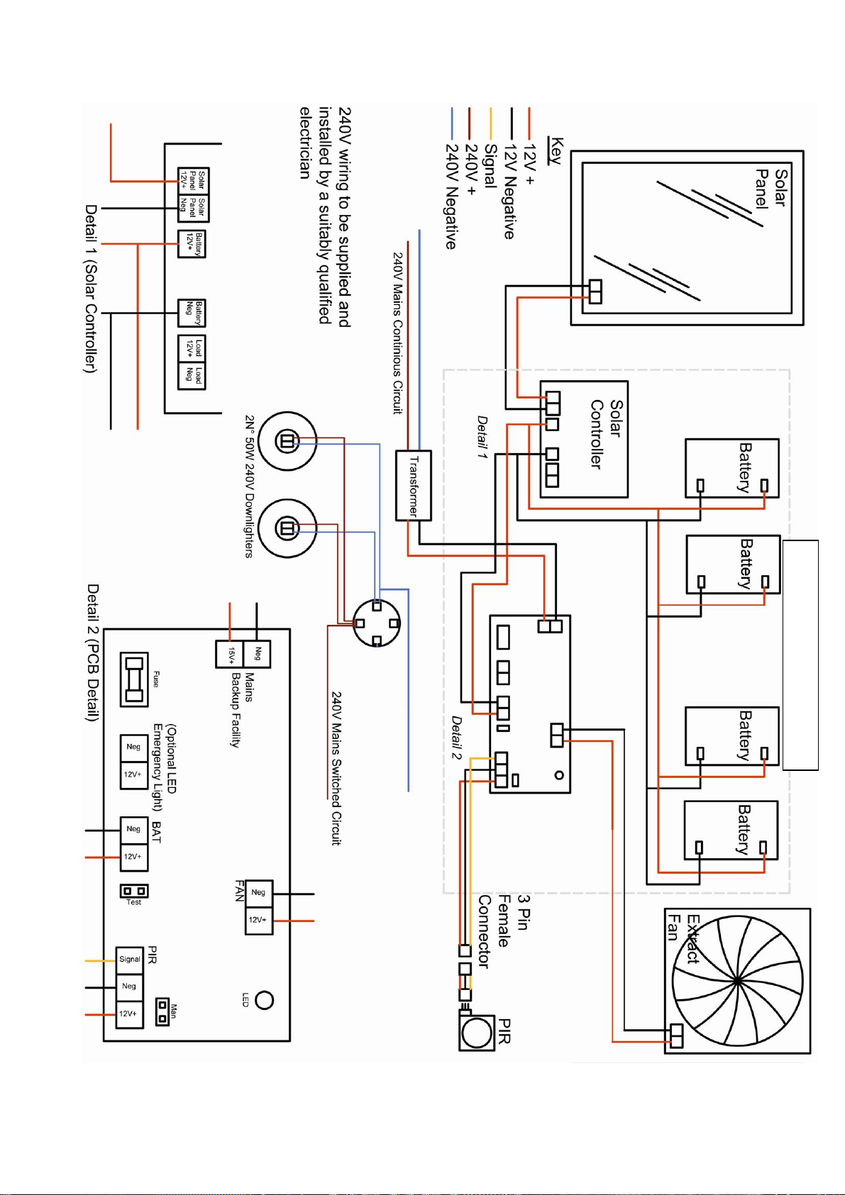
Wiring Diagram : Monodraught Sola-Vent
A
ctual number of batteries varies


