SONIQ DVR150 User manual


SAFETY PRECAUTIONS
CAUTION
RISK OF ELECTRIC SHOCK
DO NOT OPEN
WARNING
- TO PREVENTFIRE OR SHOCK HAZARD,DO NOT USE THIS PLUG WITHAN EXTENSION CORD,
RECEPTACLE OR OTHEROUTLET UNLESS THE BLADESCAN BE FULLY INSERTED TO PRESENT
BLADE EXPOSURE.
- TO PREVENTFIRE OR SHOCK HAZARD.DO NOT EXPOSE THIS APPLIANCETO RAIN OR MOISTURE.
- TO PREVENTELECTRICAL SHOCK, MATCH WIDE BLADE PLUGTO WIDE SLOTFULLY INSERT.
IMPORTANT SAFETY INSTRUCTIONS
1. Read theseinstructions.
2. Keep theseinstructions.
3. Heed allwarnings.
4. Follow allinstructions.
5. Do not use this apparatus near water.
6. Clean only with dry cloth.
7. Do not block any ventilation openings. Install inaccordance with the manufacturer’s instructions.
8. Do not install near any heat sources suchas radiators, heat registers, stoves, orother apparatus
(including amplifiers) thatproduce heat.
9. Do not defeat the safety purpose of thepolarized or grounding type plug.A polarized plug hastwo
blades with one wider than the other. Agrounding type plug has two bladesand a third grounding prong.
The wide blade or the thirdprong are provided for your safety. If the provided plug doesnot fit into your
outlet, consult an electrician for replacement ofthe obsolete outlet.
10. Protect the power cord from beingwalked on or pinched particularly atthe plugs, convenience
receptacles, and at the point where theyexit from the apparatus.
11. Only use attachments/accessoriesspecified by the manufacturer.
12. Unplug the apparatus during lightening sortsor when unused for long periodof time.
13. Refer all servicing to qualified personnel.Servicing is required when the apparatushas been damaged
In any way,or plugis damaged, liquid has been spilledor objects have fallen into the apparatus, the
apparatus has been exposed to rain ormoisture, does not operate normally, or has been dropped.
This appliance shall not beexposed to dripping or splashingwater and that no objectfilled with liquids
such as vases shall beplaced on apparatus.
This lightning flash with
arrowhead symbol, within an
equilateral triangle, is intended
to alert the user tothe presence
of uninsulated “Dangerous
voltage” within the product’s
enclosure that may be of
sufficient magnitude to constitute
a risk.of electric shock topersons.
Warning: To reduce the risk of
electric shock, do not remove
cover (or back) no user-
serviceable parts inside. refer
Servicing to qualified service
personnel.
The exclamation point
within an equilateral triangle is
intended to alert the user tothe
presence of important operating
and maintenance (servicing)
instructions in the literature
accompanying the appliance.
The symbol for Class II (DoubleInsulation)
This symbol means that the unitcomplies with
European safety and electrical interference directives.

SAFETY PRECAUTIONS

CONTENTS
BASIC INFORMATION 1
Introduction
Terms
IIIustration of the Front Panel
IIIustration of the Rear Panel
IIIustration of the Vacuum Fluorescent Display
IIIustration of the Remote Control
How to Install and Use the Remote Control
Accessories
Basic Operations
1
2
4
4
5
6
7
7
8
Summarization
Operation Steps
MANUAL RECORDING 19
19
19
Connecting to the TV set
Connecting to the Ordinary Audio System
Connecting to the Amplifier with DTS or Dolby Digital Decoders
Connecting to the Amplifier with 5.1CH Audio Input
System Connection of Recording External Signals
Connection of Using Rear Panel Input Terminals
Connection of Using Front Panel Input Terminals
SYSTEM CONNECTIONS 9
9
10
11
13
13
14
12
TIMER TASK SETTING MODE
Operation Steps(continued)
20
20
QUICK START RECORDING GUIDE 15
Summarization
Viewing the inputted Sorece
Selecting the Signal to View
How to Receive the TV Program
Manual Recording
One Touch Recording (OTR)
To Control the DV Camera Recorder by this Unit
Exiting Recording Mode
Playback USB
15
15
15
16
16
17
17
18
18
Summarization
Empty title
Entering the Editing Mode
Menu Explanation
Operation Steps
Selecting the Title/Chapter to be Edited
Insert Chapter Marker
Hiding / Unhiding Chapter
Changing the Index picture
Split Title
To Browse the Contents of the Disc and Select one Title to Play
Erasing a Title
Edit Title
Rename Title
Overwrite Title/Overwrite Disc
EDIT A TITLE RECORDED 22
22
22
22
23
23
24
24
24
24
25
25
25
26
26
26

Operation Interface and General Steps
General Setup
Screen Save Setup
Progressive/Interlace Setup
Video Output Format Setup
Restore Factory Settings
Playback settings
TV Aspect Ratio
Speaker setting
Rating Level Setup
Digital Audio Output Setup
Aualog Audio Output Setup
Record Setup
Auto Chapter Marker Setup
Default Input Signal Sources Selection
Default Recording Quality Selection
Language Settings
OSD Language Setup
DVD Menu Language Setup
DVD Subtitle Language Setup
DVD Audio Language Setup
Channel Tuning
Audio Scan Channels
Modify Channel Information
Sort Channel Order
System Clock Setup
MENU INDEX FOR INITIAL SETUP 34
34
34
34
35
35
36
36
36
37
37
38
38
39
39
40
40
41
41
41
42
42
43
43
43
45
46
CONTENTS
Entering the Playback Mode
Playback from the Menu Displayed
Playback from the Title Displayed
NORMAL PLAYBACK MODE 28
28
28
28
Ending Playback
Program and shuffle playback
Playback Process Control
Programming titles, chapters or tracks to play in a favourite order
Audio/Subtitle Selection
Angle Selection
PBC On/Off
T-Time/Tr-Time Selection
The Operations of Function Buttons
To Start Playing and Select Content to Play from Program List
Control Wipe Mode when Playing JPEG Disc
Control Zoom Mode when Playing JPEG Disc
Picture Rotating when Playing JPEG Disc
29
29
30
30
31
31
31
31
32
33
33
33
33
Specifications
Credits
APPENDIX
48
49
Trouble Shooting guide
47
47
Summarization
Entering the Disc Operation Mode
Operations
Exiting the Operation mode
EDITING A DISC OF A DVD R or DVD RW±± 27
27
27
27
27
26
Exiting the Chapter Editing Mode

Welcome!
BASIC INFORMATION
Supports 4 recording modes: HQ, SP, EP, SLP.
OTR function enables one-touch recording, convenient select the length of recording time.
Manual/automatic insertion of chapter mark.
Chapter hiding, disc locking to the recorded discs (DVD RW) and renaming the titles are available±
Title index pictures of recorded disc (DVD RW) are freely selectable.±
Multi-dubbing, multi-angle, multi-subtitle for selection.
Built-in TV tuner with TV reception function enables automatic channels scanning.
AV terminal, S-Video on the front and rear panels, DV (i. LINK/1EEE1394) and antenna input
terminals, conveniently records various program sources.
Composite video, component/progressive-scan video output terminals and TV antenna output
Terminals, Enables connection with various TV sets.
Intelligent preset timing recording function enables 20 recording tasks.
1
INTRODUCTION
Your DVD recorder is ready to record DVD RW/DVD R and toplay prerecorded DVD disc.
It is capable of recording great mass of AV inputsignals, such as TV programs, ordinary VCD or DVD
player’s signals, DV camcorderrecordings, etc. You can quickly access your recordingsin the Index
Picture Screen when playing recorded disc. The recordings youmake on the Recorder will play on
some other DVD players and DVD-ROM drives.
±±
Utilizing MPEG -II Real-Time encoding and decoding technology, being capable of directly recording
TV and external program sources on DVD R, DVD RW discs.
Recording your favorite video tapes into DVD
Built-in DV (i. LINK/1EEE1394) input jack enables fully digital high fidelity recording of digital video
camcorder signals.
±±
Progressive scan outputs to produce stabler and clearer pictures without flicker.
Built-in 5.1CH Dolby Digital surround decoder, separating 5.1CH outputs, 2CH Dolby outputs, optical
and coaxial output for digital audio.
24 bit audio DAC to produce perfect acoustic fidelity.
Regular DVD playback function is capable of playing DVD, SVCD, VCD, CD, MP3, JPEG, DVD R±
and DVD RW discs.±
Single-side discs DVD R/DVD RW(4.7GB) allow 6 hours video recording.±±

BASIC INFORMATION
TERMS
Recording quality
Depending on thecompression degree, there are four recording qualities to DVD R/RW discs with
4.7GB (12CM singleside)
±
SLP: general definition, a single-sideDVD disc can record aboutsix hours program.
EP: good definition, a single-sideDVD disc can record aboutfour hours program.
SP: better definition, a single-sideDVD disc can record abouttwo hours program.
HQ: best definition, a single-sideDVD disc can record aboutone hour program.
Title
The combined chapters of amovie or music on aDVD; For a music pieceon audio software, each
title is assigned a titlenumber enabling you to locatethe title you want.
Chapter
Sections of a movie ora music piece on aDVD that are smaller thantitles. Atitle is composed
of several chapters. Each chapteris assigned a chapter numberenabling you to locate the
chapter.
Track
Sections of a movie ora music piece on aCD-DA or VCD.Each track is assigned atrack
number enabling you to locatethe track you want.
2

TERMS (CONTINUED)
Multiple camera angles function
Certain DVD discsoffer multiple cameraangles function, When using such function,press the ANGLE
button to viewthe scenes at different camera angles.
Multiple dubbing languages function
Various dubbing languages are recorded in some DVD discs.
Multiple subtitles function
Multiple language subtitles are recorded in some DVD discs. Press the SUBTITLE button to select
different language subtitles.
BASIC INFORMATION
Regional code
Toprotect intellectual property, the involved organizations partition the world into six regions,
each of which can only use the DVD player and DVD disc with the given regional code. The
illustration on the right shows symbols of the six regions. One DVD player with a given regional
code cannot play the disc with another regional code. The partition of regional codes is as follows:
1. Canada, USA;
2. Japan, Europe, South Africa, MiddleEast,
Egypt;
3. Southeast Asia, EastAsia ;
4. Australia,New Zealand, Oceania, Central America, Mexico,Latin America,Caribbean Sea;
5. Russia, India, Africa,Korea, Mongolia;
6. China.
1 2 3456
3

4
BASIC INFORMATION
IIIustration of the Front Panel
1. Power switchbutton
2. Disc tray
3. Remote controlsensor
4. Display
5.Record button
6. Source button
7. Channel downbutton
8. Channel upbutton
9. Open/Close button
10. Stop button
11. Playbutton
12. Pause button
13. DV inputterminal
14. USB inputterminal
15. Front S-videoinput terminal
16. Front Videoinput terminal
17. Left audiochannel input terminal
18. Right audiochannel input terminal
The function ofbuttons on front panel is thesame as that of the correspondingones on remote control.
IIIustration of the Rear Panel
IN
IN
VIDEO
AUDIO
LY FL
VIDEO RL
CENTER
OPTICAL
S-VIDEOOUT
TV
RCbCr FR
S-VIDEO RR
SUBWOOFER
COAXIAL
INPUT VIDEO OUTPUT DIGITALOUT 5.1CH SURROUND AUDIO OUT
12345678910 11 13
12 14
SCART OUTSCART IN
1. TV tunerinput terminal
2. TV tuneroutput terminal
3. Rear videoinput terminal
4. Rear S-videoinput terminal
5. L/R channelaudio input terminal
6. Composite videooutput terminal
7. S-video outputterminal
8. Component videooutput terminal
9. Coaxial outputterminal
10. Optical outputterminal
11. 5.1CHoutput terminal
12. Scart input
13. Scart output
14. ACpower cord
DVD RECORDER
CHANNELSOURCERECORD STOP PLAY PAUSE
DV IN
VIDEOS-VIDEO
USB
LEFT RIGHT
AUDIO
1234
5678910 11 12
13 14 15 16 17 18

5
BASIC INFORMATION
Lighting
VFD items Light on condition Remarks
SVCD
When playing
When pausing
CHANNEL
In which channel
When playing DVDwith DTS
When playing DVDwith Dolby
digital sound
When the systemhas one or more timer
recording tasks
When recording
IIIustration of the Vacuum Fluorescent Display
Below are thelighting VFD items and their correspondingdefinitions. These itemsmay light up
accordingly depending oncondition.
When playing adisc of such type Depending on disctype
TV TS REC
PBC
REC
PBC Shows PBC duringON state
Show LOAD whenreading the disc.
Shows NO DISCwhen no disc is loaded.
TV
TS
When switch TVoutput
When switch SCARTinput

PROG RAND REP A-B
ZOOMSLOWSTOP
REV FWD PREV NEXT
MUTE POWER EJECT
I/P
GOTO CLEAR/ADD
AUDIO
SUBTITLE
ANGLE USB
1234
5678
90
N/P
SETUP DISC OP
ENTER
SOURCE RECORD
RETURN
EDIT
DISPLAY
MENU TITLE
TIMER
VOL CH
PLAY/PAUSE
2
3
4
5
7
6
9
8
10
12
11
14
16
17
18
19
20
21
13
29
31
30
33
35
36
37
38
39
40
32
26
28
27
22
23
1
24
25
15 34
6
BASIC INFORMATION
1. Power button
2. Mute button
3. I/P button
4. Number (0~9)button
5. Audio button
6. Subtitle button
7. Setup button
8. Enter button
9. / / / button
10. Source button
11. Returnbutton
12. Display button
13. Menu button
14. Volumedown button
15. Volumeup button
16. Program button
17. Random button
18. Play/Pause button
19. Stop button
20. Fast backwardbutton
21. Fast forwardbutton
22. Eject button
23. N/P button
24. Clear/Add button
25. Goto button
26. USB button
27. Angle button
28. Disc operationbutton
29. Record button
30. Edit button
31. Timerbutton
32. Titlebutton
33. Channel downbutton
34. Channel upbutton
35. A-B button
36. Repeat button
37. Zoom button
38. Slow button
39. Next button
40. Prev button
IIIustration of the Remote Control

7
BASIC INFORMATION
How to install and use the remote control
Battery Installation
Insert the batterieswhile observing the positive
(+) and Negative(-) polarities.
Service life ofbatteries
The batteries normallylast for a year although this depends on the
operation and howoften the remote control is used. If the remotecontrol
unit fails towork even when it is operated near the player, replace the
batteries with newones. Use size AAA UM-4 batteries (2pieces).
Notes:
Do not use rechargeable(Ni-Cd) batteries.
Do not attempt torecharge, short circuit, disassemble,heat or throw the
batteries into fire.
Do not drop, stepon the remote control.
Do not mix oldand new batteries. Ifthe remote control isnot going to be
used for a longtime, remove the batteries.Wipe away any electrolyte
leaking inside the remotecontrol, and install newbatteries.
Remote control operation range
The operation range of the remote control is no more
than 5m from and within about 60 degree wide in front
of the unit. The operating distance may vary according
to the brightnessof the room.
Note:
Do not pointbright lights to the remote controlsensor.
Do not placeobjects between the remote control and
the remote controlsensor.
Do not usethis remote control together with theremote
control of anyother equipment.
30
30
PROG RAND REP A-B
ZOOMSLOWSTOP
REV FWD PREV NEXT
MUTE POWER EJECT
I/P
GOTO CLEAR/ADD
AUDIO
SUBTITLE
ANGLE USB
1234
56 7 8
90
N/P
SETUP DISC OP
ENTER
SOURCE RECORD
RETURN
EDIT
DISPLAY
MENU TITLE
TIMER
VOL CH
PLAY/PAUSE
DVD RECORDER
CHANNELSOURCERECORD STOP PLAY PAUSE

BASIC INFORMATION
Basic operations
Mainly use the remote control to operate this unit. The function buttons on the front panel may also
fulfill part of the operations. Thefeedback information of the system is mainly displayed on the TV
screen, and part of the information is displayed on the VFD on the front panel.
Toswitch mode , press:[PLAY] button, [SOURCE] button,[EDIT] button, [DISCOP] button,
[SETUP] button.
In playback, recording, editingand disc operation modes,system can be controlledby “control menu”.
In playback/recording mode, the menu can bedisplayed by [DISPLAY] button. First pressing the
[DISPLAY] button,a text information bar showing the current working information will appear, and
secondly pressing the button will display the control menu. The control menuwill appear
automatically when you enterediting mode/disc operation mode.In the control menu,you can move
focus by cursor buttons to select a sub item toperform a corresponding function.
You canconfigure the system insetup mode. Pressing [SETUP]button can enter thismode, In setup
mode, the control menuis always shown. Pressing[SETUP] button again toexit.
Make a timer recordtask in timer tasksetting mode. Pressing [TIMER]button can enter thismode.
Pressing [TIMER] button inthis mode can exit.
This area shows current working mode
This area shows corresponding working information
The text information bar when system is in recording mode
Monitor Front S-VIDEO(No signal) SP
The control menu when system is in recording mode
RECORD (DVD+RW)
MODE
SOURCE
QUALITY
REC TO
New Title
Front S-VIDEO
SP
DVD-VIDEO
TRICK
TITLE
CHAPTER
TIME
Stop
01/01
01
0:02:45/2:07:09
8
The operating functions forthis unit are classifiedinto six modes:
PLAYBACK MODE,RECORDING MODE, EDITING MODE,DISC OPERATION MODE, SETUP MODE
and TIMER TASK SETTING MODE.
Component Video Input
Cr Cb Y
TV IN
S-Video
Terminal
Audio In
Video In
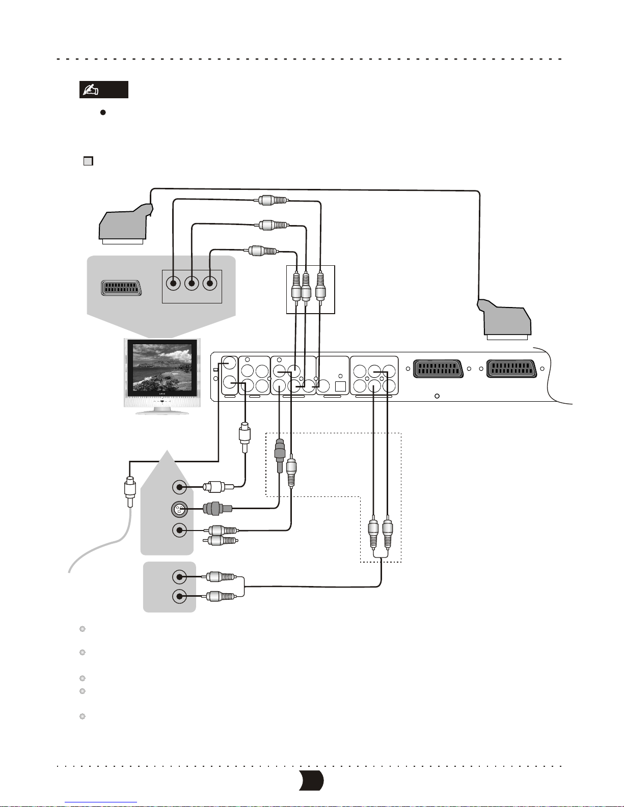
Connecting to the TV set
Illustration of the Rear Panel
Antennas Cable
75TVCoaxialCable
S-Video Cable
Video Cable
Audio Cable
connect one of the two cable
Output of this unit
Component video output
9
SYSTEM CONNECTIONS
Note
Make sure that the player and other equipments are unplugged before connecting.
This unit incorporates three video output: component video, S-video and composite video. You can connect
one of them according to your TV set’s input terminals.
Make sure that this unit outputs video by component video output terminals when you select the progressive scanning
function.
In terms of picture quality, component video is the best followed by S-video and composite video.
If the audio output is connected to a TV set, please connect L and R to the AUDIO INPUT terminals
in the same group as the VIDEO IN terminals in the TV set.
When you are not recording TV programs, you d
o not necessarily need to connect
the Antennas Cable and TV Coaxial
Cable to this unit.
Note
IN
IN
VIDEO
AUDIO
LY FL
VIDEO RL
CENTER
OPTICAL
S-VIDEOOUT
TV
RCbCr FR
S-VIDEO RR
SUBWOOFER
COAXIAL
INPUT VIDEO OUTPUT DIGITALOUT 5.1CH SURROUND AUDIO OUT
SCART OUTSCART IN
Scart /RGB input
21 pin Scart connector to 21 pin
Scart input on Television(option)

10
SYSTEM CONNECTIONS
Connecting to the Ordinarty Audio System
Illustration of the Rear Panel
Amplifier
Audio In
Audio Cable
Video Cable
IN
IN
VIDEO
AUDIO
LFL
VIDEO RL
CENTER
OPTICAL
S-VIDEOOUT
TV
RCbCr FR
S-VIDEO RR
SUBWOOFER
COAXIAL
INPUT VIDEO OUTPUT DIGITALOUT 5.1CH SURROUND AUDIO OUT
SCART IN SCART OUT
Video In Scart /RGB input
21 pin Scart connector to 21 pin
Scart input on Television(option)

Optical Cable
Coaxial Cable
Connect One of the two Cable
Coaxial in optical in
11
SYSTEM CONNECTIONS
Connecting to the Amplifier with DTS or Dolby Digital Decorders
Please refer to “System setup - Playback settings- Digital audio out setup” for details.
Illustration of the Rear Panel
IN
IN
VIDEO
AUDIO
LY FL
VIDEO RL
CENTER
OPTICAL
S-VIDEOOUT
TV
RCbCr FR
S-VIDEO RR
SUBWOOFER
COAXIAL
INPUT VIDEO OUTPUT DIGITALOUT 5.1CH SURROUND AUDIO OUT
SCART IN SCART OUT
Amplifier with Dolby Digital
or DTS digital decorder
Video In
Video Cable
Scart /RGB input
21 pin Scart connector to 21 pin
Scart input on Television(option)

SYSTEM CONNECTIONS
The Rear Panel of this Unit
Video In
Amplifier with 5.1CH Audio Input
This unit is equipped with built-in Dolby Digital decoder (Dolby AC-3 decoder). Therefore, it does not necessarily need
amplifiers with Dolby Digital processor to play DVD discs recorded with Dolby Digital Surround. When this unit is connected
to amplifiers with 5.1CH audio input to play DVD discs recorded with Dolby Digital Surround, you can enjoy theater
effect at your home. Please set the Analog Audio Output to “5.1CH”. (Please refer to”System Setup-Analog Audio Output
Setup” for details).
CENTER
L
R
FRONTSUBWOOFER SURROUND
IN
IN
VIDEO
AUDIO
LY FL
VIDEO RL
CENTER
OPTICAL
S-VIDEOOUT
TV
RCbCr FR
S-VIDEO RR
SUBWOOFER
COAXIAL
INPUT VIDEO OUTPUT DIGITAL OUT 5.1CH SURROUNDAUDIO OUT
Connecting to the Amplifier with 5.1CH Audio Input
12

SCART IN SCART OUT
21 pin Scart connector to 21 pin
Scart input on Television(option)
Scart /RGB input
SYSTEM CONNECTIONS
Connection of using rear panel input trminals
Monitoring Output
S-VIDEO
Connect One of the Two Cables
Yellow
Red
White
S-VIDEO
VIDEO AUDIO
L
R
IN
R-A/V Source
R-SV Source
TV Source
External Input Signals
Connection Antennas
or Cable TV Signals
S-VIDEO
VIDEO
AUDIO
LR
OUT
The Rear Panel of this Unit
External Source Signals
Yellow
Red
White
Red
White
Yellow
S-VIDEO
IN
IN
VIDEO
AUDIO
LY FL
VIDEO RL
CENTER
OPTICAL
S-VIDEOOUT
TV
RCbCr FR
S-VIDEO RR
SUBWOOFER
COAXIAL
INPUT VIDEO OUTPUT DIGITAL OUT 5.1CH SURROUNDAUDIO OUT
System Connection of Recording External Signals
13

System Connection of Recording External Signals
SYSTEM CONNECTIONS
Connection of using front panel input terminals
S-VIDEO
VIDEO AUDIO
L
R
IN
Monitoring Output
S-VIDEO
Connect One of the Two Cables
The Rear Panel of the Unit
Yellow
Red
White
Red
White
Yellow
IN
IN
VIDEO
AUDIO
LY FL
VIDEO RL
CENTER
OPTICAL
S-VIDEOOUT
TV
RCbCr FR
S-VIDEO RR
SUBWOOFER
COAXIAL
INPUT VIDEOOUTPUT DIGITALOUT 5.1CH SURROUND AUDIO OUT
14
Red
White
Yellow
S-VIDEO
The Front Panel of the Unit
F-A/V Source
F-SV Soutce
DV Source
External Input Signal
Digital Video Camera Recorder
DVD/VCD Player
DV
S-VIDEO
VIDEO
AUDIO
LR
OUT
DVD RECORDER
CHANNELSOURCERECORD STOP PLAY PAUSE
DV IN
VIDEOS-VIDEO
USB
LEFT RIGHT
AUDIO

QUICK START RECORDING GUIDE
Summarization
Viewing the inputted source
After entering the record mode, the source signal will be shown on the TV screen.
With this function you can get a preview of the external signals
Selecting the signal to view
Connect the system (please refer to “System
Connections-System Connection of recording
external signals”for details). Make sure the
source equipment works properly, and output the
signal intended forrecording.
Turn on this unit, then press [SOURCE] button to
enter record mode.
Press [DISPLAY] button to display the record
control menu, then highlight the “SOURCE” item.
Next, press the [ENTER] button to access the source drop down list shown as the above figure
Select the desired source from the list, press [ENTER] button, and then the TV screen will show
the corresponding picture.
Pressing [SOURCE] button can expediently view the external signals one by one.
The sequence of selecting the external signal is shown in the following.
RECORD (DVD+RW)
MODE
SOURCE
QUALITY
REC TO
New Title
Front S-VIDEO
SP
DVD-VIDEO
TRICK
TITLE
CHAPTER
TIME
Stop
01/01
01
0:02:45/2:07:09
Front CVBS
Front S-VIDEO
Rear CVBS
Rear S-VIDEO
DV
Record control menu
The source drop down list
Please refer to“System Connections-System Connection of Recording ExternalSignal ” for
the positions ofthe input signals sources on thisunit.
1
2
3
4
5
15
Playback MODE TV INPUT Front
CVBS Front
S-VIDEO Rear
CVBS Rear
S-VIDEO DV SCART
This unit hasvarious external inputsignal terminals including S-video input, compositevideo input,
TV tuner input,DVD input, andstereo audio input.You may record usingany of these video and
audio input signals.
Recordable discs compatiblewith this unitare DVD RW and DVD R. There are four recording
modes to beselected, including SLP(6 hours), EP(4 hours), SP(2 hours) and HQ(1 hour).
This unit alsoincorporates time recordingfunction which you can prepare arecording schedule
before hand andit will recordyour desired programsaccording to thepre-set schedule.
±±
Table of contents


