Sonodyne SSP 2015 User manual
SSP 2015
dual channel 15 band graphic equalizer I owners manual
www.sonodyne.com
SSP 2015 page 1
STATUTORY INFORMATION/ PRECAUTIONS
IMPORTANT SAFETY INSTRUCTIONS
1. Read and follow these instructions.
2. Do not use this apparatus near water.
3. Clean with dry cloth only.
4. Do not block any ventilation openings. Install in accordance with the manufacturer’s instructions.
5. Do not install near any heat sources such as radiators, stoves, or other apparatus (including amplifiers)
that produce heat.
6. Do not defeat the safety purpose of the polarized or grounding-type plug. A grounding type plug has two
poles and a third grounding pole. The thick pole is provided for your safety. If the provided plug does not
fit into your outlet, consult an electrician for replacement of the outlet
7. Protect the power cord from being walked on or pinched particularly at plugs, convenience receptacles,
and the point where they exit from the apparatus.
8. The apparatus shall be connected to a MAINS socket outlet with a protective earthing connection.
9. Unplug this apparatus during lightning storms or when unused for long periods of time.
10. Refer all servicing to qualified service personnel. Servicing is required when the apparatus has been
damaged in any way, such as power-supply cord or plug is damaged, liquid has been spilled or objects
have fallen into the apparatus, the apparatus has been exposed to rain or moisture, does not operate
normally, or has been dropped.
The lightning flash with arrowhead symbol within an equilateral triangle is intended to alert
the user to the presence of “un-insulated dangerous voltage” within the product’s enclosure
that may be of sufficient magnitude to constitute a risk of electric shock.
The exclamation point within an equilateral triangle is intended to alert the user to the
presence of important operating and maintenance (servicing) instructions in the literature
accompanying the product.
WARNING:
TO REDUCE THE RISK OF FIRE OR ELECTRIC SHOCK, DO NOT EXPOSE THIS APPARATUS TO RAIN OR MOISTURE
CONNECTORS
XLR-type connectors are wired as follows (IEC60268 standard): pin 1: ground, pin 2: hot (+), pin 3: cold (-).

Thank you for purchasing the Sonodyne Graphic Equalizer. Please read this manual thoroughly to get the
most out of the product and ensure long-term, trouble-free use. After reading this manual, keep it available
for future reference.
MAIN FEATURES
• Two15-band,2/3-octaveConstantQfrequencybands.
• Switchableboost/cutrangesof±6dBor±12dB
• 12dBperoctave50Hzlow-cutlter
• Frontpanelbypassswitch
• ±12dBinputgainrange
• 4segmentLEDladdersformonitoringoutputlevels
• XLRandTRSInputsandOutputs
• FrequencyResponseof10Hz~50kHz
• Dynamicrangeofgreaterthan112dB
IN THE BOX
Verify that the equalizer’s package contains the following:
• Equalizerunit
• ACpowercord
• OperatingManual
• Fourrackmountscrewsandwashers
SSP 2015 page 2
MAIN FEATURES/ IN THE BOX
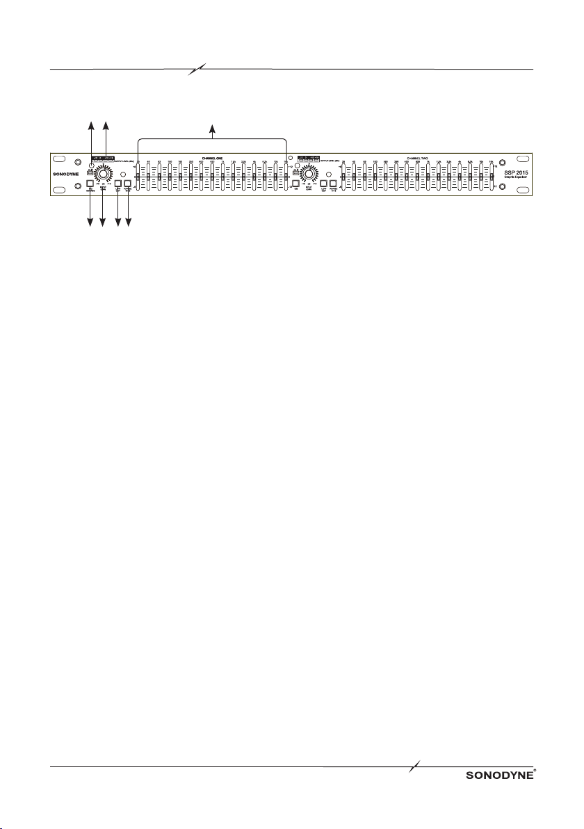
FRONT PANEL
SSP 2015 page 3
1. EQ BYPASS SWITCH and LED: Engaging this switch removes the graphic equalizer section
fromthesignalpath.TheBYPASSswitchdoesnot,however,affecttheINPUTGAINorLOWCUT
lters.TheEQBypassLEDlightsupwhentheswitchispressed
2. INPUT GAIN CONTROL: This control sets the signal level input to the equalizer. It varies the
signallevelfrom-12dBto+12dB.ItseffectcanbeviewedontheOUTPUTLEVELBARGRAPH
3. LOW CUT SWITCH:TheLOW-CUTswitchwhenpressedinsertsan18dB/octave40HzBessel
low-cut filter into the signal path
4. BOOST/CUT RANGE SELECTION SWITCH AND LEDS: This switch selects the two
boost/cutrangesoftheequalizer,either±6dBor±12dB
5. CLIP LED: ThisLEDlightswheneveranyinternalsignallevelreaches3dBbelowclipping
6. OUTPUT BAR GRAPH LEVEL: These four LEDs indicate output level of the equalizer. The
redLEDis3dBbelowclippingandismarkedas+18dBu.Itmonitorsthelevelattheoutputofthe
equalizer after all other processing
7. FREQUENCY BAND SLIDER CONTROLS: Each one of these slider potentiometers will
boostorcutatitsrespectivefrequencyby±6dBor±12dB,dependinguponthepositionofthe
BOOST/CUTRANGEswitch.Whenalltheslidersareinthecenterdetentpositionthefrequency
responseoftheequalizerisat.Thefrequencybandcentersaremarkedat2/3rdoctaveintervalson
ISO standard spacing
1 2 34
5 6 7
CONNECTING THE EQ TO YOUR SYSTEM
SSP 2015 page 4
The Equalizer has balanced inputs and outputs that can be used with any balanced or unbalanced line- level
device.
To connect the equalizer to your sound system; refer to the following steps:
• Turn off all equipment before making connections.
• Mount equalizer in a standard-width rack.
InstalltheEQsinarackwiththerackscrewsprovided.Itcanbemountedaboveorbelowanything
that does not generate excessive heat. Ambient temperatures should not exceed 113°F (45°C)
when equipment is in use. Although the unit’s chassis is shielded against radio frequency and
electromagnetic interference, extremely high fields of RF and EMI should be avoided.
• Make audio connections via XLR, barrier strip, or 1/4” TRS jacks (according to
application needs)
All three types of connectors for the inputs and outputs can be used for balanced or unbalanced
connections.
The use of more than one connector at a time for the inputs could unbalance balanced lines, cause
phase cancellation, short a conductor to ground, or cause damage to other equipment connected to
the equalizer. More than one output may be used simultaneously as long as the combined parallel load
is greater than 2kΩ.
• Select the operating range with the BOOST/CUT RANGE SELECTION switch
NOTE:Besuretoreduceaudiolevelsatthepoweramplierswhenchangingthesettingofthisswitch
as it may generate an audible transient.
• Apply power to the equalizer
Connect the AC power cord to the AC power receptacle on the back of the equalizer. Route the AC
power cord to a convenient power outlet away from audio lines. The unit may be turned on and off
from the rear panel power switch or a master equipment power switch. Since the Equalizers consume
a relatively small amount of power, the units may be left on continuously.

SSP 2015 page 5
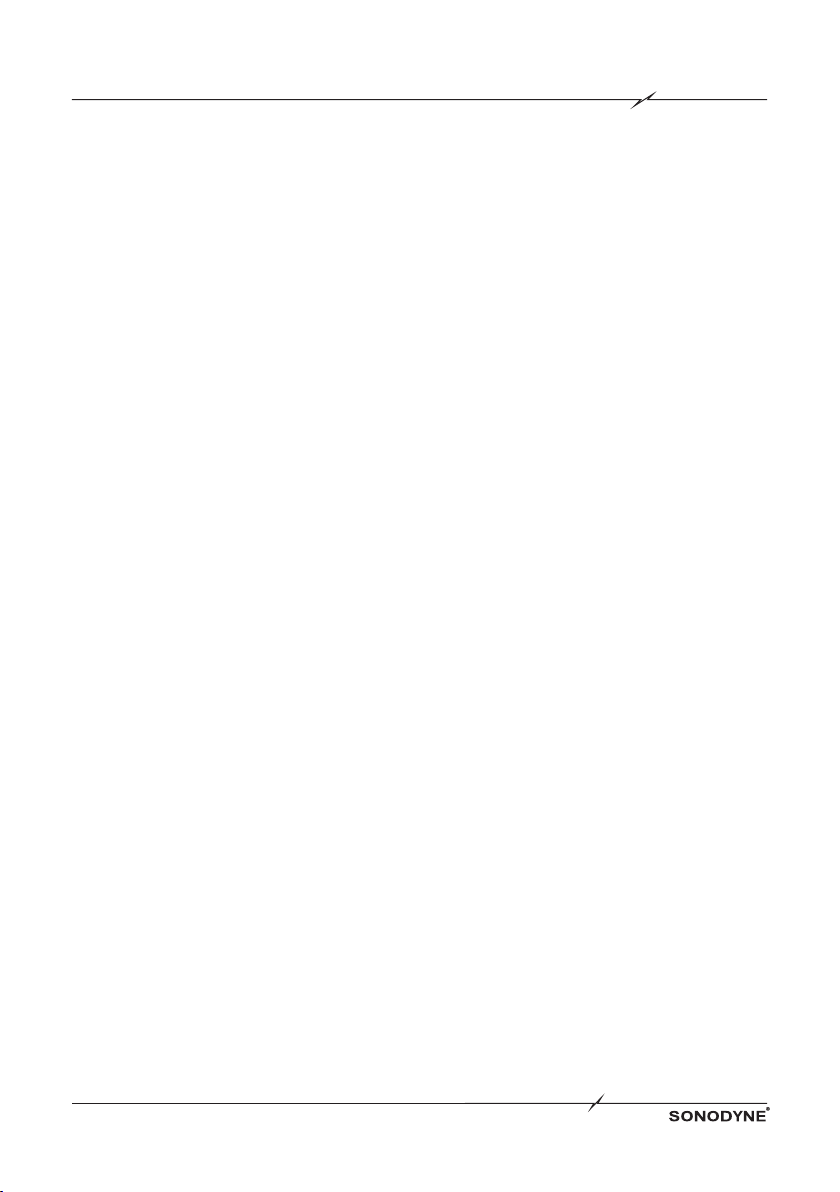
REAR PANEL/ INSTALLATION CONSIDERATIONS
1. IEC AC INLET: Connect the socket end of the mains cable provided with this unit to this socket and
the plug end to a 230V AC outlet. Ensure that the ground pin of the AC outlet has a firm connection
with the earth of the premises. This is both in the interests of your own safety as well as to eliminate
ground related hum and buzz problems.
2. OUTPUT CONNECTORS: Two types of output connectors are provided for output connections:
maleXLRtypeconnectorsand1/4”tip-ring-sleevephonejackconnectors.
3. INPUT CONNECTORS: Two types of input connectors are provided for input connections:
femalelockingXLRtypeconnectorsand1/4”tip-ring-sleevephonejackconnectors.Themaximum
inputlevelthattheequalizercanacceptwithoutclippingis+22dBu(ref:0.775Vrms)
INSTALLATION CONSIDERATIONS
HOOKUPS AND CABLING:TheEqualiserisdesignedfornominal+4dBulevels.Theequalizercan
be used with either balanced or unbalanced sources, and the outputs can be used with either balanced or
unbalanced loads, provided the proper cabling is used.
INPUT CABLE CONFIGURATIONS: The equalizer has an input impedance of 40kΩ balanced and
20kΩ unbalanced. This makes the Equalizer’s audio inputs suitable for use with virtually any low source
impedance (under 2kΩ).
OUTPUT CABLE CONFIGURATIONS: The equalizer’s output is capable of driving a 600Ω load to
+18dBu.Formaximumhumrejectionwithabalancedsource,avoidcommongroundingattheequalizer’s
inputs and outputs. Most balanced (3-conductor) cables have the shield connected at both ends. This can
result in ground loops which cause hum. If hum persists try disconnecting the shield on one or more of the
cables in the system, preferably at the input of a device, not at the output.
1 2 3

SSP 2015 page 6
NO SOUND If there appears to be no power:
•CheckthateitherthestereoormonoLEDonthefrontpanel
of the equalizer is lit
•Checkthatthepowercordisseatedproperlyintheback
panel of the crossover and that it is plugged into an active
AC power source
IF THERE APPEARS TO BE
POWER, BUT NO AUDIBLE
SIGNAL
•Conrmthatactiveaudiolinesareconnectedtothe
equalizer’s inputs and outputs
•Checkthatboththeinputandoutputgaincontrolsare
advanced sufficiently
•Checktomakesurethatyouhaveturneduptheampliers’
outputs
HUM AND/OR BUZZ If you suspect that the hum is caused by a ground loop:
•Systematicallyremoveand/orconnecttheaudiogroundsof
the devices in the signal path
•Remember,forsafetyyoumustmaintainconnectionto
chassis ground. Never lift a safety ground
IF YOU SUSPECT THE HUM IS
NOT CAUSED BY A GROUND
LOOP
•Checktheaudioatanearlierstageintheaudiochain
•Lowlevelequipmentshouldbemountedawayfrompower
amplifiers to avoid induction of this type of hum
•Becertainthatallaudiowiringexceptforloudspeakerlines
is well shielded, and that low level wiring is not run parallel
toand/orincloseproximitytoACpowerwiring
INTERMITTENT AUDIO •Checktheotherequipmentandthewiringtomakecertain
that the signal is not Intermittent earlier in the chain
•Checktheintegrityofallcablesusingacabletester
TROUBLESHOOTING

A product of the Mukherjee Innovation Centre
SonodyneTechnologiesPvt.Ltd,98NBBlockENewAlipore,Kolkata700053,INDIA
Please visit us at www.sonodyne.com
INPUTS
CONNECTORS
TYPE
IMPEDANCE
INPUT LEVEL
CMRR
1/4"TRS,femaleXLR
Electronicallybalanced/unbalanced,RFltered
Balanced40kΩ,unbalanced20kΩMax
+22dBubalancedorunbalanced
>40dB,typically>55dBat1kHz
OUTPUTS
CONNECTORS
TYPE
IMPEDANCE
MAX OUTPUT LEVEL
1/4"TRS,maleXLR(pin2hot)
Impedance-balanced/unbalanced,RFltered
Balanced100Ω,unbalanced50Ω
+21dBubalanced/unbalancedin2kΩorgreater
+18dBmbalanced/unbalanced(in600Ω)
SYSTEM PERFORMANCE
BANDWIDTH
FREQUENCY RESPONSE
DYNAMIC RANGE
SIGNAL TO NOISE RATIO
THD + NOISE
INTER CHANNEL CROSSTALK
20Hz~20kHz,+0.5/-1dB
<10Hz~>50kHz,+0.5/-3dB
Typically>112dB
Typically>90dB
<0.004%
<-80dB,20Hz~20kHz
FUNCTION SWITCHES
EQ BYPASS
LOW CUT
RANGE
Bypassesthegraphicequalizersectioninthesignalpath
Activatesthe50Hz12dB/octavehigh-passlter
Selectseither±6dBor±12dBsliderboost/cutrange
POWER SUPPLY
OPERATING VOLTAGE
POWER CONSUMPTION
MAINS CONNECTION
100-240VAC,50/60Hz
15W
IEC receptacle
PHYSICAL DIMENSIONS
DIMENSIONS (H x W x D)
PRODUCT WEIGHT
SHIPPING WEIGHT
1.75"x19"x6"
4.8 lbs
4.7 lbs
Due to continuous improvements, all specifications are subject to change
SPECIFICATIONS
Table of contents
Other Sonodyne Stereo Equalizer manuals


