Sony DCR VX2100 - Handycam Camcorder - 380 KP Guide

SECTION 6
ADJUSTMENTS
ADJ
Revision History
Revision History
Ver 1.0 2003. 10
Link
Link
Adjusting items when replacing main parts and boards
Before starting adjustment
Adjusting items when replacing main parts and boards
Before starting adjustment
LCD SYSTEM ADJUSTMENT
CAMERA SYSTEM ADJUSTMENTS
PREPARATIONS BEFORE ADJUSTMENT
CAMERA SECTION ADJUSTMENT
COLOR ELECTRONIC VIEWFINDER SYSTEM ADJUSTMENT
INITIALIZATION OF B,C,D,E,F,8 PAGE DATA
LCD SYSTEM ADJUSTMENT
COLOR ELECTRONIC VIEWFINDER SYSTEM ADJUSTMENT
CAMERA SYSTEM ADJUSTMENTS
INITIALIZATION OF B,C,D,E,F,8 PAGE DATA
PREPARATIONS BEFORE ADJUSTMENT
CAMERA SECTION ADJUSTMENT
MECHANISM SECTION ADJUSTMENT
TAPE PATH ADJUSTMENT
HOW TO ENTER PLAYBACK MODE WITHOUT CASSETTE
HOW TO ENTER RECORD MODE WITHOUT CASSETTE
TAPE PATH ADJUSTMENT
HOW TO ENTER PLAYBACK MODE WITHOUT CASSETTE
HOW TO ENTER RECORD MODE WITHOUT CASSETTE
MECHANISM SECTION ADJUSTMENT
AUDIO SYSTEM ADJUSTMENTS
VIDEO SYSTEM ADJUSTMENTS
SERVO AND RF SYSTEM ADJUSTMENT
SYSTEM CONTROL SYSTEM ADJUSTMENT
PREPARATIONS BEFORE ADJUSTMENTS
VIDEO SECTION ADJUSTMENT
AUDIO SYSTEM ADJUSTMENTS
VIDEO SYSTEM ADJUSTMENTS
SERVO AND RF SYSTEM ADJUSTMENT
SYSTEM CONTROL SYSTEM ADJUSTMENT
PREPARATIONS BEFORE ADJUSTMENTS
VIDEO SECTION ADJUSTMENT
SERVICE MODE
DATA PROCESS
ADJUSTMENT REMOTE COMMANDER
SERVICE MODE
SERVICE MODE
DATA PROCESS
ADJUSTMENT REMOTE COMMANDER
SERVICE MODE
Sony EMCS Co.
2003J1600-1
©2003.10
Published by DI CS Strategy Div.
9-876-288-51
DCR-VX2100/VX2100E
RMT-811
How to use
Acrobat Reader
How to use
Acrobat Reader
Contents of LEVEL 2 and LEVEL 3 Service Manual
CONTENTS
1. SERVICE NOTE
2. DISASSEMBLY
3. BLOCK DIAGRAMS
4. PRINTED WIRING BOARDS AND
SCHEMATIC DIAGRAMS
5. REPAIR PARTS LIST
LEVEL 2
a
a
OVERALL
POWER
CD-512, JK-267, CK-140, PD-217, LA-028, SE-147, KP-013,
MK-016, MS-209, FK-088, FT-092, MI-050, LB-100, HL-013,
MA-430, DD-216, ZM-030, RM-091 BOARD, FP-194, FP-196,
FP-188, FP-189 FLEXIBLE
EXPLODED VIEWS
ELECTRICAL PARTS
LEVEL 3
✕
✕
✕
VC-358 BOARD,
FP-594 FLEXIBLE
✕
a(VC-358 BOARD)

— 2 —
DCR-VX2100/VX2100E
TABLE OF CONTENTS
6. ADJUSTMENTS
1. Before starting adjustment···············································6-1
1-1. Adjusting items when replacing main parts and boards. ···6-2
6-1. CAMERA SECTION ADJUSTMENT ···························6-4
1-1. PREPARATIONS BEFORE ADJUSTMENT
(CAMERA SECTION) ···················································6-4
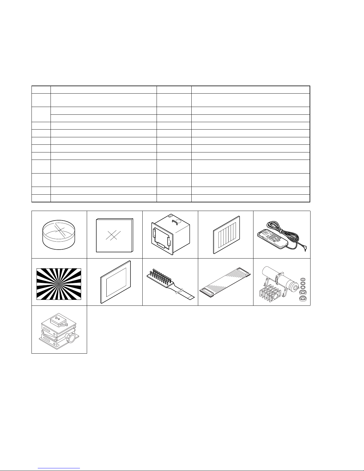
1-1-1. List of Service Tools ·······················································6-4
1-1-2.Preparations ·····································································6-5
1-1-3.Precaution ········································································6-7
1. Setting the Switch····························································6-7
2. Order of Adjustments ······················································6-7
3. Subjects ···········································································6-7
1-2. INITIALIZATION OF B, C, D, E, F, 8 PAGE DATA ·····6-8
1-2-1.INITIALIZATION OF C, D, 8 PAGE DATA ··················6-8
1. Initializing the C, D, 8 Page Data····································6-8
2. Modification of C, D, 8 Page Data ··································6-8
3. C Page Table ····································································6-8
4. D Page Table··································································6-10
5. 8 Page Table···································································6-10
1-2-2.INITIALIZATION OF B PAGE DATA·························6-11
1. Initializing the B Page Data···········································6-11
2. Modification of B Page Data ·········································6-11
3. B Page Table ··································································6-11
1-2-3.INITIALIZATION OF E, F PAGE DATA·····················6-12
1. Initializing the E, F Page Data·······································6-12
2. Modification of E, F Page Data ·····································6-12
3. F Page Table ··································································6-12
4. E Page Table ··································································6-14
1-3. CAMERA SYSTEM ADJUSTMENTS ························6-15
1. 27MHz Origin Oscillation Adjustment
(VC-358 board) ·····························································6-15
2. Zoom Key Center Adjustment ·······································6-15
3. HALL Adjustment ·························································6-16
4. Offset Adjustment··························································6-16
5. Flange Back Adjustment (Using Minipattern Box)·······6-17
6. Flange Back Adjustment (Using Flange Back Adjustment
Chart and Subject More Than 500m Away) ··················6-18
6-1. Flange Back Adjustment (1) ··········································6-18
6-2. Flange Back Adjustment (2) ··········································6-18
7. Flange Back Check························································6-19
8. Picture Frame Setting ····················································6-19
9. Pre White Balance Data Input ·······································6-20
10. Auto White Balance Standard Data Input ·····················6-20
11. MAX GAIN Adjustment ···············································6-21
12. LV Standard Data Input ·················································6-21
13. White Balance ND Filter 1 Compensation····················6-22
14. White Balance ND Filter 2 Compensation····················6-22
15. Auto White Balance Adjustment ···································6-23
16. Color Reproduction Adjustment (ND Filter OFF) ········6-23
17. Color Reproduction Adjustment (ND Filter 1)··············6-24
18. Color Reproduction Adjustment (ND Filter 2)··············6-24
19. White Balance Check ····················································6-25
20. Steady Shot Adjustment ················································6-26
20-1. Steady Shot Adjustment (1)···········································6-27
20-2. Steady Shot Adjustment (2)···········································6-28
1-4. COLOR ELECTRONIC VIEWFINDER SYSTEM
ADJUSTMENT·····························································6-29
1. VCO Adjustment (VC-358 board) ································6-29
2. Bright Adjustment (VC-358 board)·······························6-30
3. Contrast Adjustment (VC-358 board) ···························6-30
4. White Balance Adjustment (VC-358 board) ·················6-31
1-5. LCD SYSTEM ADJUSTMENT ···································6-31
1. VCO Adjustment (PD-217 board) ·································6-32
2. Bright Adjustment (PD-217 board) ·······························6-32
3. Black Limit Adjustment (PD-217 board) ······················6-33
4. PSIG GRAY Adjustment (PD-217 Board) ····················6-33
5. Contrast Adjustment (PD-217 board) ····························6-34
6. Center Level Adjustment (PD-217 board) ·····················6-34
7. V-COM Adjustment (PD-217 board) ····························6-35
8. White Balance Adjustment (PD-217 board)··················6-35
6-2. MECHANISM SECTION ADJUSTMENT ··················6-36
2-1. HOW TO ENTER RECORD MODE WITHOUT
CASSETTE ···································································6-36
2-2. HOW TO ENTER PLAYBACK MODE WITHOUT
CASSETTE ···································································6-36
2-3. TAPE PATH ADJUSTMENT ········································6-36
1. Preparation for Adjustment ···········································6-36
2. Procedure after operations·············································6-36
6-3. VIDEO SECTION ADJUSTMENTS ···························6-37
3-1. PREPARATIONS BEFORE ADJUSTMENTS ············6-37
3-1-1.Equipment Required······················································6-37
3-1-2.Precautions on Adjusting ···············································6-38
3-1-3.Adjusting Connectors ····················································6-39
3-1-4.Connecting the Equipment ············································6-39
3-1-5.Alignment Tapes ····························································6-40
3-1-6.Input/Output Level and Impedance ·······························6-40
3-2. SYSTEM CONTROL SYSTEM ADJUSTMENT········6-41
1. Initialization of B, C, D, E, F, 8 Page Data ···················6-41
2. Serial No. Input ·····························································6-41
2-1. Company ID Input·························································6-41
2-2. Serial No. Input ·····························································6-41
3. Battery End Adjustment ················································6-43
3-3. SERVO AND RF SYSTEMADJUSTMENT ···············6-44
1. Cap FG Duty Adjustment (VC-358 Board)···················6-44
2. T reel FG Duty Adjustment (VC-358 Board)················6-44
3. PLL f0& LPF f0Adjustment (VC-358 Board)··············6-44
4. Switching Position Adjustment (VC-242 Board) ··········6-45
5. AGC Center Level and APC & AEQAdjustment ·········6-45
5-1. Preparations before adjustments····································6-45
5-2. AGC Center Level Adjustment (VC-358 Board) ··········6-45
5-3. APC & AEQ Adjustment (VC-358 Board) ···················6-46
5-4. Processing after Completing Adjustments ····················6-46
6. PLL f0& LPF f0Final Adjustment (VC-358 Board)·····6-46
3-4. VIDEO SYSTEM ADJUSTMENTS·····························6-47
3-4-1. Base Band Block Adjustments······································6-47
1. Chroma BPF f0Adjustment (VC-358 Board)················6-47
2. S VIDEO OUTY LevelAdjustment (VC-358 Board) ··6-47
3. S VIDEO OUT Chroma Level Adjustment
(VC-358 Board)·····························································6-48
4. VIDEO OUTY, Chroma Level Check
(VC-358 Board)·····························································6-48
3-4-2. BIST Check ··································································6-49
1. Playback System Check ················································6-49
1-1. Preparations for Playback··············································6-49
1-2. IC301 TRX (RF) PB BIST Check·································6-49
1-3. IC301 AUD (ABUS) PB BIST Check···························6-49
1-4. IC301 VFD PB BIST Check ·········································6-49
1-5. IC301 ENCODER BIST Check ····································6-51
1-6. Processing after Completing Playback System Check ····6-52
2. Recording System Check ··············································6-53
2-1. Preparations for recording ·············································6-53

— 3 —
DCR-VX2100/VX2100E
2-2. IC301 TRX (RF) REC BIST Check·····························6-53
2-3.
Processing after Completing Recording System Check ···
6-53
3-5. AUDIO SYSTEM ADJUSTMENTS ····························6-54
1. Playback Level Check ···················································6-55
2. Overall Level Characteristics Check ·····························6-55
3. Overall Distortion Check···············································6-55
4. Overall Noise Level Check············································6-55
5. Overall Separation Check··············································6-55
6-4. SERVICE MODE ··························································6-56
4-1. ADJUSTMENT REMOTE COMMANDER ················6-56
1. Using the adjustment remote commander ·····················6-56
2. Precautions upon using the adjustment remote
commander ····································································6-56
4-2. DATA PROCESS···························································6-57
4-3. SERVICE MODE ··························································6-58
1. Setting the Test Mode ····················································6-58
2. Emergence Memory Address ········································6-58
2-1. EMG Code (Emergency Code) ·····································6-58
2-2. MSW Code ····································································6-59
3. Bit value discrimination ················································6-60
4. Switch check (1) ····························································6-60
5. Switch check (2) ····························································6-61
6. Switch check (3) ····························································6-61
7. Record of Use check······················································6-62
8. Record of Self-diagnosis check ·····································6-62
*Color reproduction frame is shown on page 6-63.

6-1
DCR-VX2100/VX2100E
1. Before starting adjustment
EVR Data Re-writing Procedure When Replacing Board
The data that is stored in the repair board, is not necessarily correct.
Perform either procedure 1 or procedure 2 or procedure 3 when replacing board.
Procedure 1
Save the EVR data of the machine in which a board is going to be replaced. Download the saved data after a board
is replaced.
Remove the EEPROM and install it.
(Former board) (New board)
(Machine to be repaired) (Machine to be repaired)
(The same model of the same destination)
Save the data.
Download the data.
PC
Procedure 2
Remove the EEPROM from the board of the machine that is going to be repaired. Install the removed EEPROM
to the replaced board.
Procedure 3
When the data cannot be saved due to defective EEPROM, or when the EEPROM cannot be removed or
installed, save the data from the same model of the same destination, and download it.
After the EVR data is saved and downloaded, check the
respective items of the EVR data.
(Refer to page 6-3 for the items to be checked.)
(Machine before starting repair) (Machine after a board is replaced)
PC PC
Save the EVR data
to a personal computer.
Download the saved
data to a machine.
SECTION 6
ADJUSTMENTS

6-2
DCR-VX2100/VX2100E
Lens device
Prism assy (Including 3 CCD imagers)
VAP unit
Mechanism deck
EVF block LCD902 (LCD panel)
LCD block LCD901 (LCD panel)
LCD block ND901 (Fluorescent tube)
LCD block Inverter unit
Control switch(CF-4980)
Mechanism deck M901 (Drum motor)
Mechanism deck M902 (Capstan motor)
FP-594 board H902 (T reel FG sensor)
SE-147 board SE600, 601 (PITCH/YAW sensor)
PD-217 board IC2101 (RGB driver (LCD))
PD-217 board IC2103 (Timing generator (LCD))
LB-100 board D201 (Back light (EVF))
VC-358 board IC1802 (RGB driver (EVF))
VC-358 board IC1803 (Timing generator (EVF))
VC-358 board IC705, X701 (Timing generator)
VC-358 board IC704 (S/H, AGC)
VC-358 board IC706 (A/D converter)
VC-358 board IC802 (Camera micro processor)
VC-358 board IC1301 (LINE IN/OUT amp)
VC-358 board IC301 (DV signal process)
VC-358 board IC101 (EQ, A/D CONV., PLL)
VC-358 board IC102 (REC/PB amp)
VC-358 board IC803 (EVR)
Replaced parts
Block replacement Parts replacement
zz
z
zz z
zzzz
zz
zz zz z
zz zz
zz zz z
zz zz
zz zz
zz zz
zz zz
zz zz
zz zz
zz zz
zz
z
z
zz
zzz
z
z
z
z
zz
z
zz
zzz z
zzzz
zz
zz
zz
zz zz
zz zz
zz zz
z
zz
zz
1-1. Adjusting items when replacing main parts and boards.
• Adjusting items when replacing main parts
When replacing main parts, adjust the items indicated by zin the following table.
Note1: When replacing the drum assy., reset the data of page: 2, address: A2 to A4 to “00”. (Refer to “Record of Use check” of “5-4. SERVICE MODE”)
Table. 6-1-1(1).
Adjustment
Section
Initialization
of B, C, D, E,
F, 8 page data
Camera
EVF
LCD
Mechanism
System control
Servo, RF
Video
Adjustment
Initialization of C, D, 8 page data
Initialization of B page data
Initialization of E, F page data
27MHz origin oscillation adj.
Zoom key center adj.
HALL adj.
Offset adj.
Flange back adj.
Pre-white balance data input
AWB standard data input
MAX GAIN adj.
LV standard data input
White balance ND filter 1 compensation
White balance ND filter 2 compensation
Auto white balance adj.
Color reproduction adj. (ND filter OFF)
Color reproduction adj. (ND filter 1)
Color reproduction adj. (ND filter 2)
Steady shot adj.
VCO adj.
Bright adj.
Contrast adj.
White balance adj.
VCO adj.
Bright adj.
Black limit adj.
PSIG GRAY adj.
Contrast adj.
Center level adj.
V COM adj.
White balance adj.
Tape path adj.
Serial No. input
Battery end adj.
CAP FG duty adj.
T reel FG duty adj.
Switching position adj.
AGC center level adj.
APC & AEQ adj.
PLL f0& LPF f0adj.
Chroma BPF f0adj.
S VIDEO OUTY level adj.
S VIDEO OUT Cr, Cb level adj.

6-3
DCR-VX2100/VX2100E
Board replacement
zz
zz
zz
zz
zz
zzz
zz z
zz z z
zz z z
zz z z
zz z z
zz z z
zz z z
zz z z
zz z z
zz z z
zz z z
zz z z
zz z
zz
zz
zz
zzz
zz z
zz z
zz z
zz z
zz z
zz z
zz z
zz z
z
zz
zz
zz
zz z
zz
zz
zz
zz
zz
zz
zz
CD-512 board (COMPLETE)
FP-594 board (COMPLETE)
VC-358 board (COMPLETE)
SE-147 board (COMPLETE)
PD-217 board (COMPLETE)
LB-100 board (COMPLETE)
VC-358 board IC801 (EEPROM)
VC-358 board IC502 (EEPROM)
VC-358 board IC1406 (EEPROM)
Supporting
• Adjusting items when replacing a board or EEPROM
When replacing a board or EEPROM, adjust the items indicated by zin the following table.
Table. 6-1-1(2).
Adjustment
Section
Initialization
of B, C, D, E,
F, 8 page data
Camera
EVF
LCD
Mechanism
System control
Servo, RF
Video
Adjustment
Initialization of C, D, 8 page data
Initialization of B page data
Initialization of E, F page data
27MHz origin oscillation adj.
Zoom key center adj.
HALL adj.
Offset adj.
Flange back adj.
Pre-white balance data input
AWB standard data input
MAX GAIN adj.
LV standard data input
White balance ND filter 1 compensation
White balance ND filter 2 compensation
Auto white balance adj.
Color reproduction adj. (ND filter OFF)
Color reproduction adj. (ND filter 1)
Color reproduction adj. (ND filter 2)
Steady shot adj.
VCO adj.
Bright adj.
Contrast adj.
White balance adj.
VCO adj.
Bright adj.
Black limit adj.
PSIG GRAY adj.
Contrast adj.
Center level adj.
V COM adj.
White balance adj.
Tape path adj.
Serial No. input
Battery end adj.
CAP FG duty adj.
T reel FG duty adj.
Switching position adj.
AGC center level adj.
APC & AEQ adj.
PLL f0& LPF f0adj.
Chroma BPF f0adj.
S VIDEO OUTY level adj.
S VIDEO OUT Cr, Cb level adj.

6-4
DCR-VX2100/VX2100E
J-1 J-2
J-6
J-3
J-7 J-8
J-4 J-5
Fig. 6-1-1.
J-9 J-10
J-11
Ref. No.
J-1
J-2
J-3
J-4
J-5
J-6
J-7
J-8
J-9
J-10
J-11
Name
Filter for color temperature correction (C14)
ND filter 1.0
ND filter 0.3
Pattern box PTB-450
Color chart for pattern box
Adjustment remote commander
Siemens star chart
Clear chart for pattern box
CPC-13 jig
Extension cable (50P, 0.5mm)
Mini pattern box
Camera table
Parts Code
J-6080-058-A
J-6080-808-A
J-6080-818-A
J-6082-200-A
J-6020-250-A
J-6082-053-B
J-6080-875-A
J-6080-621-A
J-6082-443-A
J-6082-496-A
J-6082-353-B
J-6082-384-A
Usage
Auto white balance adjustment/check
White balance adjustment/check
White balance check
White balance check (2 sheets used)
For checking the flange back
For adjusting the video section
For adjusting the color viewfinder
For extension between the CD-512 board (CN100) and
the VC-358 board (CN025)
For adjusting the flange back
6-1. CAMERA SECTION ADJUSTMENT
1-1. PREPARATIONS BEFORE ADJUSTMENT (CAMERA SECTION)
1-1-1. List of Service Tools
•Oscilloscope •Color monitor •Vectorscope
•Regulated power supply •Digital voltmeter

6-5
DCR-VX2100/VX2100E
Fig. 6-1-2.
1-1-2. Preparations
Note 1: For details of how remove the cabinet and boards, refer to “2.
DISASSEMBLY”.
Note 2: When performing only the adjustments, the lens block and boards
need not be disassembled.
1) Connect the equipment for adjustments according to Fig. 6-1-3.
Note 3: As removingthe (upper) handle block(removingthe FK-088 board
CN501) means removing the lithium 3V power supply (ZM-030
board BT801, 802), data such as date, time, user-set menus will
belost.Aftercompleting adjustments, resetthesedata.If thecabinet
(R) has been removed, the self-diagnosis data, data on history of
use (total drum rotation time etc. ) will be lost. Before removing,
note down the self-diagnosis data and the data on history use (data
of page: 2, address: A2 to AA). (Refer to “SELF-DIAGNOSIS
FUNCTION”for the self-diagnosis data, and to “6-4.Service
Mode”for the data on the history use.)
Note 4: Setting the “Forced Camera Power ON”Mode
1) Select page: 0, address: 01, and set data: 01.
2) Select page: D, address: 10, set data: 01, and press the PAUSE
button of the adjustment remote commander.
The above procedure will enable the camera power to be turned
on with the control switch block (CF-4980) removed. After
completing adjustments, be sure to exit the “Forced Camera
Power ON Mode”.
Note 5: Exiting the “Forced Camera Power ON”Mode
1) Select page: 0, address: 01, and set data: 01.
2) Select page: D, address: 10, set data: 00, and press the PAUSE
button of the adjustment remote commander.
3) Select page: 0, address: 01, and set data: 00.
Pattern box
Front of the protection glass
95 cm

6-6
DCR-VX2100/VX2100E
Fig. 6-1-3.
AC POWER
ADAPTOR
[CONNECTION OF EQUIPMENT]
CPC-13 jig
(J-6082-443-A)
CPC cover
AC IN
Adjustment remote
commander (RM-95)
LANC
jack
Screw
(M2
×
5),
lock ace, p2

6-7
DCR-VX2100/VX2100E
1-1-3. Precaution
1. Setting the Switch
Unless otherwise specified, set the switches as follows and perform
adjustments without loading cassette.
1. POWER switch (CF-4980 block) ..........................CAMERA
2. DEMO MODE (Menu display) .......................................OFF
3. DIGITAL ZOOM (Menu display) ...................................OFF
4. STEADY SHOT (Menu display) .....................................OFF
5. DISPLAY (Menu display) .................................V-OUT/LCD
6. DISPLAY (CK-140 board) ............................................... ON
7. AUTO LOCK (MK-016 board) ................................... AUTO
8. ND FILTER (Lens block) ................................................OFF
9. FOCUS switch (FP-188 flexible).......................... MANUAL
10. BACK LIGHT (FP-189 flexible) .....................................OFF
11. SPOT LIGHT (FP-189 flexible) ......................................OFF
12. PICTURE EFFECT (CK-140 board)...............................OFF
13. DIGITAL EFFECT (CK-140 board)................................OFF
14. ZEBRA (CK-140 board)..................................................OFF
15. 16 : 9 WIDE (Menu display)............................................OFF
16. AUTO SHUTTER (Menu display) ..................................OFF
17. PROG.SCAN (Menu display) ..........................................OFF
2. Order of Adjustments
Basically carry out adjustments in the order given.
H
A=B
AB BA
Enlargement
V
0 ±0.1msec
Electronic beam scanning frame
CRT picture frame
BA
Difference in level
Yellow
Cyan
Green
White
Magenta
Red
Blue
Yellow
Cyan
Green
White
Magenta
Red
Blue
Color bar chart (Color reproduction adjustment frame )
Fig. a
(Video output terminal
output waveform)
Fig. b (TV monitor picture)
Adjust the camera zoom and direction to
obtain the output waveform shown in Fig. a
and the TV monitor display shown in Fig. b.
Fig. 6-1-4
3. Subjects
1) Color bar chart (Standard picture frame).
When performing adjustments using the color bar chart, adjust
the picture frame as shown in Fig. 6-1-4. (Standard picture
frame)
2) Clear chart (Standard picture frame)
Remove the color bar chart from the pattern box and insert a
clearchart in itsplace. (Do notperform zoom operationsduring
this time.)
3) Flange back adjustment chart
Make the chart shown in Fig. 6-1-5 usingA0 size (1189 mm ×
841 mm) black and white vellum paper.
White
Black
841m
m
1189mm
Fig. 6-1-5
Note: Use matte vellum paper bigger thanA0, and make sure the edges of
the black and white paper joined together are not rough.

6-8
DCR-VX2100/VX2100E
1-2. INITIALIZATION OF B, C, D, E, F, 8 PAGE
DATA
1-2-1. INITIALIZATION OF C, D, 8 PAGE DATA
1. Initializing the C, D, 8 Page Data
Note1: If “Initializing the C, D, 8 Page Data”is performed, all data of the
C page, D page and 8 page will be initialized. (It is impossible to
initialize a single page.)
Note2: If the C, D, 8 page data has been initialized, the following
adjustments need to be performed again.
1) Modification of C, D, 8 page data
2) Serial No. input
3) Servo and RF system adjustments
4) Video system adjustments
5) Color viewfinder system adjustments
6) LCD system Adjustments
Adjustment Page C
Adjustment Address 10 to FF
Adjustment Page D
Adjustment Address 10 to FF
Adjustment Page 8
Adjustment Address 00 to FF
Initializing Method:
Order Page
Address
Data Procedure
1 0 01 01 Set the data
2 3 81 Check that the data is “00”.
3 3 80 0A Set the data, and press the
PAUSE button.
4 3 80 Check that the data changes to
“1A”
5 Perform “Modification of C, D,
8 Page Data”.
2. Modification of C, D, 8 Page Data
If the C, D, 8 page data has been initialized, change the data of the
“Fixed data-2”address shown in the following tables by manual
input.
Modifying Method:
1) Before changing the data, select page: 0, address: 01, and set
data: 01.
2) New data for changing are not shown in the tables because
they are different in destination. When changing the data, copy
the data built in the same model.
Note: If copy the data built in the different model, the camcorder may
not operate.
3) When changing the data, press the PAUSE button of the
adjustment remote commander each time when setting new
data to write the data in the non-volatile memory.
4) Check that the data of adjustment addresses is the initial value.
If not, change the data to the initial value.
Processing after Completing Modification of C, D, 8 Page data
Order Page
Address
Data Procedure
1 2 00 29 Set the data
2 2 01 29 Set the data, and press the
PAUSE button.
Note: If the following symptoms occur after completing of the
“Modificationof C, D, 8 page data”, checkthat the data of the “Fixed
data-2”addresses of D page are same as those of the same model of
the same destination.
1) The battery end mark on the LCD or viewfinder screen is flashing.
2) The power is shut off so that unit cannot operate.
3. C Page Table
Note: Fixed data-1: Initialized data. (Refer to “1. Initializing the C, D, 8
Page Data”.)
Fixed data-2: Modified data. (Refer to “2. Modification of C, D, 8
Page Data”.)
00 to 0F
10
11
12
13
14 to 15
16
17
18
19
1A
1B
1C
1D
1E
1F
20
21
22
EE
00
00
00
E0
E0
2A
2A
32
32
25
3E
3E
DC
99
Switching position adj.
Fixed data-1
Cap FG duty adj.
Treel FG duty adj.
AEQ adj.
Fixed data-1
AEQ adj.
Fixed data-1
AGC center level adj.
PLL f0adj.
APC adj.
LPF f0adj.
Address Remark
Initial value

6-9
DCR-VX2100/VX2100E
23 to 24
25
26
27
28
29
2A to 2B
2C
2D to 41
42
43 to 55
56
57 to 81
82
83 to 85
86
87
88
89
8A to 9A
9B
9C
9D
9E
9F
A0
A1 to A2
A3
A4
A5
A6
A7
A8
A9 to AA
AB
AC
AD
AE
AF
B0
B1
B2
B3
B4
B5
B6
B7
B8
B9
BA to BF
C0
C1
C2
C3
C4
C5
C6
C7
C8
C9
CA to D5
D6
D7
D8
D9
DA
DB
DC
DD
DE
DF
E0
E1 to E5
E6
E7
E8
E9
EA
EB
EC
ED
EE
EF
F0 to F3
F4
F5
F6
F7
F8
F9
FA
FB
FC
FD
FE
FF
88
E3
A1
04
20
03
08
00
46
01
01
00
00
00
00
00
00
00
00
00
00
00
00
00
00
00
Fixed data-1
S VIDEO outY level adj.
S VIDEO out Cr level adj.
S VIDEO out Cb level adj.
Chroma BPF f0adj.
PLL f0fine adj.
Fixed data-1
APC adj.
Fixed data-1
Fixed data-2
Fixed data-1
Fixed data-2
Fixed data-1
Fixed data-2
Fixed data-1
Fixed data-2
Fixed data-1
Fixed data-2
Fixed data-1
Fixed data-2
Fixed data-1
Fixed data-2
Fixed data-1
Fixed data-2
Fixed data-1
Fixed data-2
Fixed data-1
Fixed data-2
Fixed data-1
Fixed data-2
Fixed data-2
Fixed data-1
Fixed data-2
Fixed data-1
Fixed data-2
Fixed data-1
Fixed data-2
Fixed data-1
Serial No. input
Fixed data-1
Emergency memory address
Address Remark
Initial value Address Remark
Initial value
Table. 6-1-2.
C Page

6-10
DCR-VX2100/VX2100E
4. D Page Table
Note: Fixed data-1: Initialized data. (Refer to “1. Initializing the C, D, 8
Page Data”.)
Fixed data-2: Modified data. (Refer to “2. Modification of C, D, 8
Page Data”.)
00 to 0F
10
11 to 12
13
14
15 to 2C
2D
2E
2F to 3F
40
41 to 47
48
49
4A
4B
4C
4D to 90
91
92
93
94
95
96
97
98
99
9A to A1
A2
A3
A4
A5
A6
A7
A8
A9
AA
AB
AC
AD
AE
AF
B0 to B9
BA
BB to C5
C6
C7 to D0
D1
D2 to D6
D7
D8 to FF
00
91
97
A8
BD
C8
60
60
AC
90
80
30
71
71
9F
AA
0A
AE
85
75
40
30
Test mode
Fixed data-1
Fixed data-2
Fixed data-1
Fixed data-2
Fixed data-1
Fixed data-2
Fixed data-1
Battery end adj.
Fixed data-1
Fixed data-2
VCO adj. (EVF)
Fixed data-1
Bright adj. (EVF)
Fixed data-1
White balance adj. (EVF)
Contrast adj. (EVF)
Fixed data-1
VCO adj. (LCD)
V-COM adj. (LCD)
Bright adj.(LCD)
Black limit adj.(LCD)
PSIG GRAY adj.(LCD)
White balance adj. (LCD)
Contrast adj. (LCD)
Center level adj.(LCD)
Fixed data-2
Fixed data-1
Fixed data-2
Fixed data-1
Fixed data-2
Fixed data-1
Fixed data-2
Fixed data-1
Fixed data-2
Fixed data-1
Address Remark
Initial value
Table. 6-1-3.
5. 8 Page Table
Note: Fixed data-1: Initialized data. (Refer to “1. Initializing the C, D, 8
Page Data”.)
Fixed data-2: Modified data. (Refer to “2. Modification of C, D, 8
Page Data”.)
Table. 6-1-4.
Address Remark
00 to 0A
0B
0C to 8F
90
91 to 98
99
9A to FF
Fixed data-1
Fixed data-2
Fixed data-1
Fixed data-2
Fixed data-1
Fixed data-2
Fixed data-1

6-11
DCR-VX2100/VX2100E
1-2-2. INITIALIZATION OF B PAGE DATA
Note: When reading the B page data, insert a “Memory Stick”into the
“Memory Stick”slot.
Switch setting:
POWER................................................................. MEMORY
1. Initializing the B Page Data
Note: If the B page data has been initialized, the following adjustments
need to be performed again.
1) Modification of B page data
Adjustment Page B
Adjustment Address 00 to FF
Initializing Method
Order Page
Address
Data Procedure
1 0 01 01 Set the data.
2 5 01 F3 Set the data, and press PAUSE
button.
3 5 00 01 Set the data, and press PAUSE
button.
4 5 01 Wait for three seconds.
5 5 00 Check that the data is “00”.
6 5 02 Check that the data is “00”.
7 Perform “Modification of B
Page Data”.
2. Modification of B Page Data
If the B page data has been initialized, change the data of the “Fixed
data-2”address shown in the following tables by manual input.
Preparations:
Order Page
Address
Data Procedure
1 2 8F 00 Set the data, and press PAUSE
button.
2 2 8F 03 Set the data, and press PAUSE
button.
3 2 8F 00 Set the data, and press PAUSE
button.
Modifying Method:
1) Before changing the data, select page: 0, address: 01, and set
data: 01.
2) New data for changing are not shown in the tables because
they are different in destination. When changing the data, copy
the data built in the same model.
Note: If copy the data built in the different model, the camcorder may
not operate.
3) When changing the data, press the PAUSE button of the
adjustment remote commander each time when setting new
data to write the data in the non-volatile memory.
Processing after Completing Modification of B Page data:
Order Page
Address
Data Procedure
1 2 00 29 Set the data.
2 2 01 29 Set the data, and press PAUSE
button.
3. B Page Table
Note: Fixed data-1: Initialized data. (Refer to “1. or 3. Initializing the B
Page Data”.)
Fixed data-2: Modified data. (Refer to “2. or 4. Modification of B
Page Data”.)
Table. 6-1-5.
Address Remark
00 to 3A
3B
3C to 3D
3E
3F to 5F
60
61 to FF
Fixed data-1
Fixed data-2
Fixed data-1
Fixed data-2
Fixed data-1
Fixed data-2
Fixed data-1

6-12
DCR-VX2100/VX2100E
3. F Page Table
Note1: Fixed data-1: Initialized data. (Refer to “1. Initializing the E, F
Page Data”.)
Fixed data-2: Modified data. (Refer to “2. Modification of E, F
Page Data”.)
Note2: NTSC model : DCR-VX2100
PAL model : DCR-VX2100E
00 to 0F
10 to 14
15
16 to 1B
1C
1D
1E
1F
20
21
22
23
24
25
26
27
28
29
2A
2B
2C
2D to 33
34
35
36
37
38
39
3A
3B
3C
3D
3E
3F
40
41
42
43
44
45
46
47
48 to 49
4A
4B
4C to 52
53
54
55
80
60
40
00
15
00
2E
AE
2B
44
43
B2
16
00
00
8B
88
6C
D6
E6
46
45
3F
3F
16
A8
38
76
50
50
EB
D5
20
20
00
00
Fixed data-1
Fixed data-2
Fixed data-1
27MHz origin osc. adj.
Fixed data-1
HALL adj.
AWB standard data input
Flange back adj.
MAX GAIN adj.
Fixed data-1
Auto white balance adj.
Flange back adj.
LV standard data input
Fixed data-1
Steady shot adj.
Fixed data-1
Color reproduction adj.
(ND filter OFF)
Fixed data-1
WB ND filter 1 compensation
Fixed data-1
Fixed data-2
80
60
60
00
15
00
2E
AE
2B
44
43
B2
16
00
00
8B
90
8F
D6
E6
46
00
19
00
27
A8
38
76
50
50
EB
D5
20
20
00
00
Address Remark
Initial value
NTSC PA L
1-2-3. INITIALIZATION OF E, F PAGE DATA
1. Initializing the E, F Page Data
Note1: If “Initializing the E, F Page Data”is performed, all data of the E
page and F page will be initialized. (It is impossible to initialize a
single page.)
Note2: If the E, F page data has been initialized, following adjustments
need to be performed again.
1) Modification of E, F page data
2) Camera system adjustments
Adjustment Page F
Adjustment Address 10 to FF
Adjustment Page E
Adjustment Address 00 to FF
Switch setting:
POWER..................................................................CAMERA
Initializing Method:
Order Page
Address
Data Procedure
1 0 01 01 Set the data.
2 6 01 Set the following data, and press
PAUSE button.
2D: DCR-VX2100 (NTSC)
2F : DCR-VX2100E (PAL)
3 6 03 01 Set the data, and press PAUSE
button.
4 6 02 Check that the data changes to
“01”.
5 Perform “Modification of E, F
Page Data”.
2. Modification of E, F Page Data
If the E, F page data has been initialized, change the data of the
“Fixeddata-2”addressshowninthe followingtablebymanual input.
Modifying Method:
1) Before changing the data, select page: 0, address: 01, and set
data: 01.
2) New data for changing are not shown in the tables because
they are different in destination. When changing the data, copy
the data built in the same model.
Note: If copy the data built in the different model, the camcorder may
not operate.
3) When changing the data, press the PAUSE button of the
adjustment remote commander each time when setting new
data to write the data in the non-volatile memory.
4) Check that the data of adjustment addresses is the initial value.
If not, change the data to the initial value.
Processing after Completing Modification of E, F Page data
1) Select page: 0, address: 01, and set data: 00.
2) Turn off the power and turn on again.

6-13
DCR-VX2100/VX2100E
56 to 5C
5D
5E to 5F
60
61 to 6A
6B
6C
6D
6E
6F
70
71 to 7B
7C
7D
7E to 80
81
82
83
84 to 8D
8E
8F to 9E
9F
A0 to A5
A6
A7
A8 to AA
AB
AC to B1
B2
B3 to B9
BA
BB to C5
C6
C7
C8
C9 to CA
CB
CC
CD
CE
CF
D0
D1
D2
D3
D4
D5
D6 to DF
E0
E1 to EC
ED
EE to F4
F5
F6
F7
80
89
80
89
Fixed data-1
Zoom key center adj.
Fixed data-1
Fixed data-2
Fixed data-1
Fixed data-2
Fixed data-1
HALL adj.
Fixed data-1
Fixed data-2
Fixed data-1
Fixed data-2
Fixed data-1
Fixed data-2
Fixed data-1
Fixed data-2
Fixed data-1
Fixed data-2
Fixed data-1
Fixed data-2
Fixed data-1
Fixed data-2
Fixed data-1
Fixed data-2
Fixed data-1
Fixed data-2
Fixed data-1
Fixed data-2
Fixed data-1
Fixed data-2
Fixed data-1
Fixed data-2
Fixed data-1
Fixed data-2
Fixed data-1
Fixed data-2
Fixed data-1
Fixed data-2
Address Remark
Initial value
NTSC PA L
Table. 6-1-6.
Address Remark
Initial value
NTSC PA L
F8
F9
FA to FC
FD
FE to FF
Fixed data-1
Fixed data-2
Fixed data-1
Fixed data-2
Fixed data-1
F Page

6-14
DCR-VX2100/VX2100E
4. E Page Table
Note1: Fixed data-1: Initialized data. (Refer to “1. Initializing the E, F
Page Data”.)
Fixed data-2: Modified data. (Refer to “2. Modification of E, F
Page Data”.)
Note2: Refer to “2. Modification of E, F Page Data”for the camera
microprocessor version.
Note3: NTSC model: DCR-VX2100
PAL model : DCR-VX2100E
Table. 6-1-6.
8C
8D
8E
8F
90
91
92
93
94
95
96
97 to 9D
9E
9F to A0
A1
A2
A3
A4
A5
A6 to A7
A8
A9 to AB
AC
AD
AE to B0
B1
B2
B3
B4 to B9
BA
BB to C3
C4
C5 to CB
CC
CD
CE
CF to D9
DA
DB
DC to EB
EC
ED to F2
F3
F4
F5
F6
F7
F8
F9
FA to FD
FE
FF
00
00
EB
D5
20
20
00
00
EB
D5
20
20
Fixed data-2
WB ND filter 2 compensation
Color reproduction adj. (ND filter 2)
Fixed data-2
Fixed data-1
Fixed data-2
Fixed data-1
Fixed data-2
Fixed data-1
Fixed data-2
Fixed data-1
Fixed data-2
Fixed data-1
Fixed data-2
Fixed data-1
Fixed data-2
Fixed data-1
Fixed data-2
Fixed data-1
Fixed data-2
Fixed data-1
Fixed data-2
Fixed data-1
Fixed data-2
Fixed data-1
Fixed data-2
Fixed data-1
Fixed data-2
Fixed data-1
Fixed data-2
Fixed data-1
Fixed data-2
Fixed data-1
Fixed data-2
Fixed data-1
Fixed data-2
Fixed data-1
Fixed data-2
00 to 03
04
05
06
07
08 to 10
11
12 to 13
14
15 to 29
2A
2B
2C
2D
2E
2F
30 to 47
48
49
4A to 4C
4D
4E to 51
52
53
54
55
56
57
58
59
5A
5B
5C
5D
5E
5F
60 to 61
62
63
64
65
66 to 74
75
76 to 89
8A
8B
10
10
80
80
80
EB
D5
20
20
Fixed data-1
Fixed data-2
Fixed data-1
Fixed data-2
Fixed data-1
Fixed data-2
Fixed data-1
Pre-white balance data input
Fixed data-1
Offset adj.
Fixed data-1
Fixed data-2
Fixed data-1
Fixed data-2
Fixed data-1
Fixed data-2
Fixed data-1
Fixed data-2
Fixed data-1
Fixed data-2
Fixed data-1
Fixed data-2
Fixed data-1
Fixed data-2
Fixed data-1
Fixed data-2
Fixed data-1
Color reproduction adj. (ND filter 1)
Fixed data-1
Fixed data-2
Fixed data-1
Fixed data-2
Fixed data-1
10
10
80
80
80
EB
D5
20
20
Address Remark
Initial value
NTSC PAL
Address Remark
Initial value
NTSC PA L

6-15
DCR-VX2100/VX2100E
1-3. CAMERA SYSTEM ADJUSTMENTS
Before perform the camera system adjustments, check that the
specified values of “VIDEO SYSTEM ADJUSTMENT”are
satisfied.
1. 27MHz Origin Oscillation Adjustment
(VC-358 board)
Set the frequency of the clock for synchronization.
If deviated,the synchronization will be disrupted and the color will
become inconsistent.
Subject Not required
Measurement Point Pin rj of IC771 or pin qf of IC706
Measuring Instrument Frequency counter
Adjustment Page F
Adjustment Address 1C
Specified Value f=13500000 ±68Hz
Adjusting method:
Order Page
Address
Data Procedure
1 0 01 01 Set the data.
2 F 1C Change the data and set the
frequency (f) to the specified
value.
3 F 1C Press PAUSE button.
4 0 01 00 Set the data.
2. Zoom Key Center Adjustment
Set theA/D value center of the microprocessor to the center voltage
of the zoom key.
If deviated, the zoom lens operates of itself ,even if the zoom key is
the center position.
Subject Not required
Measurement Point Display data of page: 6, address: 50
Measuring Instrument Adjustment remote commander
Adjustment Page F
Adjustment Address 5D
Note: Don’t touch the zoom switch during adjustment.
Adjusting method:
Order Page
Address
Data Procedure
1 0 01 01 Set the data.
2 6 50 Read the data, and this data is
named D50.
3F5DD
50 Set the data, and press PAUSE
button.
4 0 01 00 Set the data.
VC-358 board
IC771
IC706
10076
26 25 12
1324
4837 1
1
51
75
50
Fig. 6-1-6.

6-16
DCR-VX2100/VX2100E
3. HALL Adjustment
For detecting the position of the lens iris, adjust AMP gain and
offset.
Subject Not required
Measurement Point Display data of page 1 (Note1)
Measuring Instrument Adjustment remote commander
Adjustment Page F
Adjustment Address 1E, 1F, 70
Specified Value 1 88 to 8C
Specified Value 2 15 to 19
Note1: Displayed data of page 1 of the adjustment remote commander.
1 : XX : XX IRIS display data
Note2: Check that the data of page: 6, address: 02 is “00”. If not, to page:
6, address: 01, set data: 00, and press the PAUSE button.
Adjusting method:
Order Page
Address
Data Procedure
1 0 01 01 Set the data.
2 6 94 8A Set the data.
3 6 95 17 Set the data.
4 6 01 6D Set the data, and press PAUSE
button.
5 6 02 Check that the data changes to
“01”. (Note3)
6 6 01 00 Set the data, and press PAUSE
button.
Note3: Theadjustmentdatawill be automaticallyinputtopage: F, address:
1E, 1F, 70.
Checking method:
Order Page
Address
Data Procedure
1 6 04 03 Set the data.
2 6 01 01 Set the data, and press PAUSE
button.
3 1 Check that the IRIS display data
(Note1) satisfies the specified
value 1.
4 6 01 03 Set the data, and press PAUSE
button.
5 1 Check that the IRIS display data
(Note1) satisfies the specified
value.2.
Processing after CompletingAdjustments:
Order Page
Address
Data Procedure
1 6 01 00 Set the data, and press PAUSE
button.
2 6 04 00 Set the data.
3 6 94 00 Set the data.
4 6 95 00 Set the data.
5 0 01 00 Set the data.
4. Offset Adjustment
Adjust so that theAGC OUT potential lies within the specified value
of the digital clamp.
Subject Not required
Measurement Point DDS display data of LCD or TV
monitor (Note1)
Measuring Instrument
Adjustment Page E
Adjustment Address 2D, 2E, 2F
Specified Value 70 to 90
Note 1: DDS display data of LCD or TV monitor.
CA 00 0000
CA 00 00XX Object data
Adjusting method:
Order Page
Address
Data Procedure
1 0 01 01 Set the data.
2 D 11 02 Set the data, and press PAUSE
button.
3 6 01 05 Set the data, and press PAUSE
button.
4 E 0C 02 Set the data, and press PAUSE
button.
5 6 04 1F Set the data.
6 E 2D Change the data and adjust the
DDS display data (Note 1) to
“80”. (Rch offset adjustment)
7 E 2D Press PAUSE button.
8 6 04 20 Set the data.
9 E 2E Change the data and adjust the
DDS display data (Note 1) to
“80”. (Gch offset adjustment)
10 E 2E Press PAUSE button.
11 6 04 21 Set the data.
12 E 2F Change the data and adjust the
DDS display data (Note 1) to
“80”. (Bch offset adjustment)
13 E 2F Press PAUSE button.
Processing after CompletingAdjustments
Order Page
Address
Data Procedure
1 D 11 00 Set the data, and press PAUSE
button.
2 E 0C 00 Set the data, and press PAUSE
button.
3 0 01 00 Set the data.
4 6 01 00 Set the data, and press PAUSE
button.
5 6 04 00 Set the data.
6 Turn off the power and turn on
again.

6-17
DCR-VX2100/VX2100E
5. Flange Back Adjustment
(Using Minipattern Box)
The inner focus lens flange back adjustment is carried out
automatically. In whichever case, the focus will be deviated during
auto focusing/manual focusing.
Subject Siemens star chart with ND filter for
the minipattern box (Note2)
Measurement Point Check operation on TV monitor
Measuring Instrument
Adjustment Page F
Adjustment Address 24 to 2B, 36 to 3D, 5D
Note1: Dark Siemens star chart.
Note2: Check that the data of page: 6, address: 02 is “00”. If not, to page:
6, address: 01, set data: 00, and press the PAUSE button.
Switch setting:
ND FILTER......................................................................OFF
(The data of page: 6, address: 9D is “00”.)
Preparations:
1) The minipattern box is installed as shown in the following
figure.
Note: The attachment lenses are not used.
2) Install the minipattern box so that the distance between it and
the front of the protection glass of the camcorder is less than
3cm. (Remove the lens hood.)
3) Makethe height of the minipatternboxand the camcorder equal.
4) Check that the output voltage of the regulated power supply is
the specified voltage.
5) Check that at both the zoom lens TELE end and WIDE end,
the center of the Siemens star chart and center of the exposure
screen coincide.
Specified voltage: The specified voltage varies according to the
minipattern box, so adjust the power supply
output voltage to the specified voltage written
on the sheet which is supplied with the
minipattern box.
Adjusting method:
Order Page
Address
Data Procedure
1 0 01 01 Set the data.
2 6 01 13 Set the data, and press PAUSE
button. (Note3)
3 6 01 27 Set the data, and press PAUSE
button.
4 6 02 Check that the data changes to
“01”. (Note4)
5 F 2A Check that the data is “00”to
“07”.
Note3: Don’t touch the zoom switch. If you touch the zoom switch, the
zoom center adjustment data will be rewritten in the value which
isn’t correct.
Note4: The adjustment data will beautomatically input to page: F, address::
24 to 2B, 36 to 3D, 5D.
Processing after CompletingAdjustments:
Order Page
Address
Data Procedure
1 6 01 00 Set the data, and press PAUSE
button.
2 6 02 00 Set the data.
3 0 01 00 Set the data.
4 Turn off the power and turn on
again.
5 Perform “Flange Back Check”.
Minipattern box
Below 3 cm
Camcorder
Camera
table
Red (+)
Black (–)
Yellow (SENS +)
White (SENS –)
Black (GND)
Need not connected
Regulated power supply
Output voltage : Specified voltage ±0.01Vdc
Output current : more than 3.5A
Fig. 6-1-7.
Other manuals for DCR VX2100 - Handycam Camcorder - 380 KP
6
This manual suits for next models
2
Table of contents
Other Sony Film Camera manuals