Southbend CM-31 User manual
Ea
southbend
A MIDDLEBY COMPANY
IMPORTANT
FOR FUTURE REFERENCE
Please complete this information
and retain this manual for the life
of the equipment.
MODEL #
SERIAL #
DATE PURCHASED
i
OWNER’S MANUAL
INSTALLATION
USER’S GUIDE
SERVICE
PARTS
INFRA-RED
CHEESE MELTERS
MODELS:
CM-3lC; CIU-36; CM-32; CM-S-60
CM-mPC, cNl=3lw, CMal, CM-3lP
CMeoc, cM-64,cM-60=60
CNMOPC,
CM4OW, CM-60,CM-6OP
Theseinstructionsshouldbe read
thoroughly before atterrpting instaMion. in&Won
and Start Up should be petformd by a qualified service techridan. The Mariutacturer,
Southbend (1100 Old HoneyaRt FM.,Fuquay-Varina, hbrih Camfina2Z26), infomrs you
~atunlessthe.~ninstnrctionsfortheabove~SwthbendFHodud~
~andperformedbyaquatifisd~technician,(apelsan~encedinand
krmhdgeable aweming the instalWon of cofnmefcial gas.aWof ektrkal oook@
equipment) then the terms and conditions of the Manufachner’sLimited warranty will be
rendefedvoidandnowanantyofanykindshaUapply.
If the equipment has been changed, attered, modified or repaired by other than a
quaiified sewice technician during or after the 12~mordhlimitedwarranty period, then
themanufadurershan~beCaMefotanyindde~orconsequentiald;unagestoany
person or to any property which may result from the use of the equipment thereafter.
Some States do not allow the exclusion or limitation of incidental or consequential
~~,so~e~~li~orexdusiontheretomaynot~toyou.
Intheeve~~youhaveanypuestionsconcemingtheinstal(ation,use,care,orsenriceof
the pfocm, write Customer Service Department, Southbend, 1100 Old Honeycult Rd,
Fuquay-Vartna, North Camha 27526.
MFRAIRED
CHEESE MELTERS
(Manual Section BR)
Chqmtdationa! Youhavejut purched me at the best piecss uf
heavy-dufy, mefiial e00king
equipment
on the market today.
You
will 5nd that your new equipment, like
all Southbend equipment, has been designed and manufachaed to
some of the
toughest
standards in the indumy -
thoss of Southbend Cqmration. Each piece of Southbend
equipment
haa been cn~fblly engineered and
de&ns have ken vsrified through laboratory m end field
instabtions in some of the more strenuous commercial cooking applic&m. With proper ca,m and field
maintenance, you will experience years of relisble, &mbb-&ee operation from your So&bend equipment. To
get
the best msul% it% important that you read tbis manual cmwfizlly.
TABTZ OF CONTENTS
SE~‘.KNO.KNO~-ON
IrltdMon . . . . . . ..--.*..........................*......-.-...................
. . . . . . . . . . . . . . . . . . . . . . . ..-.-.-..........~-........................... ;
SEXXONTWO-UsER’SGuIDE
. . . . . . . . ..*.....I-...............*...............*-.......~......... 192
ouredusive Schwank cfmmictilehumm
in8bouth&theusualtime,withlesgas
mheatingsoccmdaryanfacesasisn~in
CA-ON: POST INZ?ROiMINENT Lt2CtUTON~S~UcIIoNS To BE FOLLOWED m
!lT?E EVENT THE SMELL OF GAS IS DlZ2YZmD. Z!EIS RWO2’Ui@l7ON S&ALL BE
OBT~ERO~LOCXLWSIP+~
t 1
I
I
FoRYouRsAEETY
DO NOT STORE OIt USE GASOLTNE OR OTHBR-LEVAPORSAND
~QUBWINTBEVICINlTYOF’~OZUNYOTHEEtAppw[ANcE.
KEEPAREAAROUND APPLuNcBs~ANDcLEARFaoMcoMB-s.
INTHEEVENTAGASODOEISDETecTeD,~DOWN~UIfMENTA31‘THE
MAIN SHUTOFF VALVE AND CONTACT TEE LOCAL GAS COMPANY OR GAS
-FoR-cE9
l
WARNING-W- wIuBEvoIDIR
ASERVICEWORKISPERFORMEDBYOTHERTaANAQUAL;IFIED
TlWHNICIAN.
KOTKERTHANGENMNE souTHBENDBlEPLA~ PAaTs ARE
INSTALLED.
1lOOOklHOMyCiJItROild
Fquay.NC27526
(919)662-9161
FAX(919)552-9796
INFRA-RED CHEESE
MELTERS
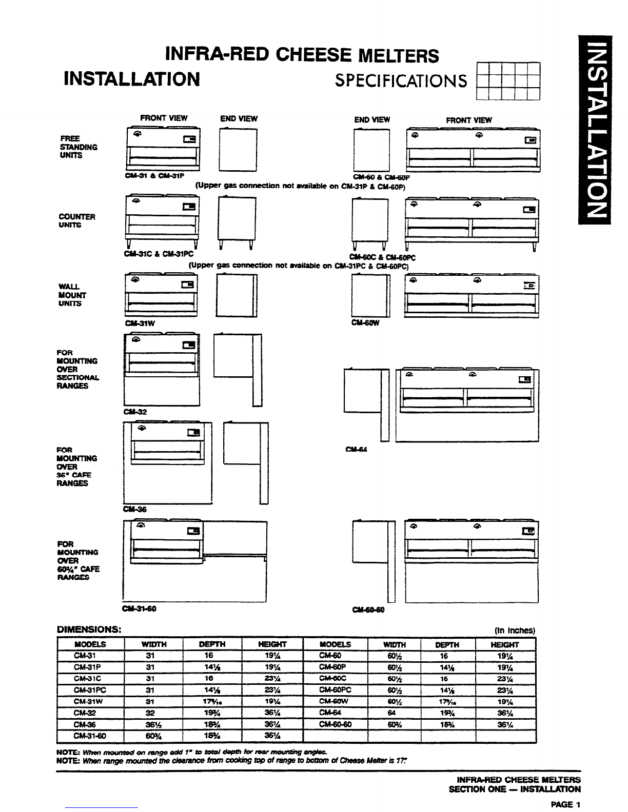
INSTALLATION
SPECIFICATIONS mj
COUNTER
UNITS
DIMENSIONS:
FRONT VEW END VIEW END VIEW FRONTVIEW
ClFn&CS3lP cNbOacN-6w
(Upper gas connection not mfaitablc on W-31P tk chbmop~
I”i--l
RLiJ
CM-3lC&CM-3lPC (Upper gas comeion not mdable on C%3lPC &
(In Inches)
t . YooEL9 1 NElGHr
CM-31 31 16 19% @.w 16 19%
CMMP 31 ?4’/$ 19% CM6OP w2 14’h 19%
CMCMC
INFRA-REO CHEESE MEUERS
SEC’IION ONE - lNSlALLA3lON
PAGE 1
I
INSTALLATION
I
WARNING: THESE PROCEDURES MUST BE FOLLOWED BY QUALIFIED
PERSONNEL OR WARRANTY WILL BE VOIDED. I
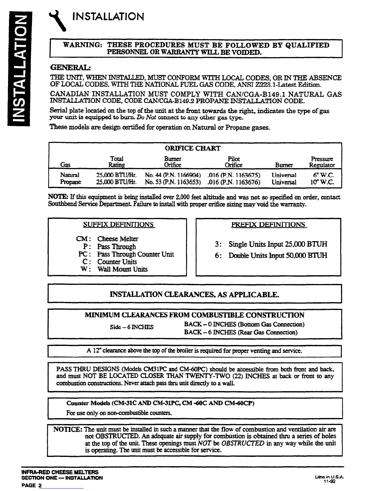
THE UNiT, WHEN INS’T%LLXD,MUSI’ CONFORM WITH LOCAL CODES, OR IN THE ABSENCE
OF LOCAL CODES, WITH THE NATIONAL FUEL MS CODE, ANSI 2!2!23.1-LatestEdition.
CANADIAN INSTALLATION MUST COMPLY WITH CAN/CGA-B149.1 NATURAL GAS
INSTALLATION CODE, CODECAN/CGA-B149.2 PROPANE INSTALLATION CODE.
Serial plate located on the top ofthe unit at the hnt towards the right, indicates the type of gas
your unit is equipped to burn, DoNot connectto any other gas type.
These models are design certified for operation on Natural or Propane gases.
ORIFICECHART
Total Burner
pilot
Pressure
Gas Rating orifice Olifie Bllnler Regulator
NCitllId 25,000BTU/Hr. No.44(P-N.3166904) -016(P-N.1163675) universal 6”W.C.
Propane 25,000BTU/I+. No.53(P.N.1163653) ,016(P.N.1163676) universal lo” WC.
NOTE: If this equipmeatis king installedover2,000feet altitude and was not sospecifiedon order, contact
Swthbend ServiceDepartmenLFailuretoinstallwith properorificesizingmay‘voidthe warranty.
SUFFlX DEFlNITiONS PRERX
DEFINITIONS
CM: CheeseMelter
P: PassThrough
PC : PassThough Counter Unit
c : collnter units
W : Wall Mount Units
3: Single Units Input 25,000 BTUH
6: Double Units Input 50,000 BTUH
.
INSTALLATION CLEARANCES, AS APPLICABLE.
MINIMUM CLEARANCES FROM
COMBUSTIBLE CONSTRUCTION
Side-6INCHES BACK - 0 INCHES (BottomGasConnection)
BACK-6 INCHES(RearGasConnection)
I
A 12”clearanceabovethetop
ofthebroilerisrequiredfor properventingandservice. I
PASSTHRU DESIGNS(ModelsCM3IPC andCM-6OPC)shouldbeaccessiblefrom bothfront and back,
and mustNOT BE LOCATED CLOSERTHAN TWENTY-TWO (22) INCHES at back or front to any
combustionconstructions.Neverattachpassrhruunitdirectlyto awall.
I
Counter Models (CM-31C AND CM31PC, CM -6OCAND CM4OCP)
Foruseonly onnoncombustiblecounters. I
NOTICE: The unit mustbeinstalledin suchamannerthat the flow of combustion andventilation air are
not OBSTRUCTED.An adequateair supply for combustionis obtained thm a seriesof holes
atthe top of theunit.TheseopeningsmustNOT be OBST?WXED in any way while the unit
is operating.Theunitmustbeaccessiblefor service.
t
IWRA-WDCHEESEMELTERS
SECTION ONE-INSTALLATION
PAGE 4
lithoin
USA
11-92
INSTALLATION
NOTE: No additional clearance from the sides and back is required for service, as the units are
serviceablefrom the front.
E2iHAUST FANSAND CANOPIES:
Canopies are set over ranges, ovens, etc., for ventilation purposes. It is recommendedthat a canopy
extend 6” past appliance and be located 6’6” from the floor. Filters should beinstalled at an angle of
45 degrees or more with the horizontal. This position prevents dripping of grease and facilitates
collecting the run-off grease in a drip pan, usually installed with a filter. A strong exhaust fan tends
to create a vacuum in the room and may interfere with burner performance or may extinguish pilot
flames. Fresh air openings approximately equal to the fan area will relieve such vacuum. In caseof
unsatisfactory performance on an appliance, check with the exhaust fan in the “OFE” position.
NOTE: Be sure to inspect and clean ventilation system according to the ventilation equipment
manufacturerk instructions.
I
WARNING: THESE PROCEDURES MUST BE FOLLOWED BY QUALIFIED
PERSONNELORWARRANTY WIUBEVOIDED.
GAS CONNECTIOM
l.AtX&i.fied pressme regulator designed for the type of gas for which the unit is equipped is packed
with the unit.
2. If applicable, the vent line from the gas appliance pressure regulator shall be installed to the
outdoors in accordance with local codesor, in the absence of local codes,with the National Fuel
Gas Code, ANSI Z223.1-Latest Edition. Canadian installation must comply with CANXGA-
B149.1 Natural Gas Instahation Code,CodeCAN/CGA-B1492 Propane Installation Code.
3. The gas supply connection is l/2” NIT and can be made at either the rear or the bottom on the
left-hand side. Both of these connections are closed by a l/2” NPl’ plug as shipped from the
factory. Passthru models only have bottom connection.
AREA&
Bemove the 1/2” NPT plug at the rear lefi side. Insert a V2” NPT nipple, 3 inches long, into
this fitting. At the inlet of this I.&!”NPT nipple install the pressure regulator. Take care that
the flow of gas thru this pressure regulator is asindicated by an axrowon this controL Install a
1/2”NPTserviceshutoffvalvetotheregulatorandcoMecta1/2”NPTgassupplylinetothis
valve.
B. BO’ITOE
Removethe l/2” NPT plug at the bottom lefi area and use the samepmcedure as above for the
connection.
I
CAUTIONBESURETOHOLDPRESSUREREGULAZ#RWIZHAWRENCH~Z7GHlENLNG
SUPPLYPIPEToAVOIDDAMAGEToTIEEREGULA7UR,VvALvE,ANDO7HERCOMPONENZS.
I
4.TheunitshouId13econnected~ytothetypeofgasfarwhichitisequipped.Checktypeof~on
rating plate. On all threaded connections, the pipe compound must be approved for use with
natural and propane gas.
5. Make sure burner valve is in the ‘Ol?F’ position before connecting gas to unit. Test all pipe
connections thoroughly for gas leaks. Use soapy water only for testing onall gases.
6.Turn on burners and bleed supply line, then turn burners off.
7. Light pilot and adjust so that flame is approximately
W8"
long. Adjustment is tbru a 318”dia.
0ueni.w in the white area of the valve indicator decal.
I --------------- --- -~~-
SUPPLYPrPINGSYSllEMAT~STP~SSURES~UAL~O~LESS~1/2PSIG(3.45KPa). 1
wFRA4?EDaEEsEMELlERs
SEmONE-iNSTALL4TlON PAGE 3
\
INSTALLBTION
ST&EB;;~LmOm~D BY QUALIFIED
.
A I” NPT line is provided at the rear for the connection. Each unit is equipped with an internal
pressure regulator which is set
for 4”
WC. manifold pressure for natural gas and 10” WC. for
propane gas. Use 1/8” pipe tap on the burner manifold for checking pressure.
An adequate gas supply is imperative. Undersized or low pressure lines will restrict the vohrme of
gasrequked for satisfactory perhonnauce.A steady supply pressure, 6” W.C. for natural gas aud 10”
W.C. for propane gas, is recommended. With all uuits operating simultaneously, the manifold
pressure on all units should not show any appreciable drop. Fluctuations of more than 25% on
natural gas, and 10% on propane gas, will create pilot problems and affect burner operating
characteristics. Contact your gas companyfor correct supply line sizes.
Purge the supply line to clean out any dust, dirt, or other foreign matter before connecting the line
to the unit. It is recommended that an individual manual shutoff valve be installed in the gas
supply line to the unit. Use pipe joint compound which is suitable for use with LP gas on all
threaded connections. Test pipe connectiousthoroughly for gas leaks. USE SOAPY WATER ONLY
FOR TESTING ON ALL GASES. NEVER USE AN OPEN FLAME TO CHECK FOR GAS LEAKS.
ALL CONNECTIONS MUST BE CHECKED FOR IEAKS, AFTER TIIE UNIT HAS BEEN PUT
IN OPERATION.
lNPRAaEDcNEEsEMELTERs
SECTION ONE-INSTALLATION
PAGE 4
INSTALLATIONr
I
WARNING: THESE PROCEDURES MUST BE FOLLOWED BY QUALIFIED
PERSONNELORWARRANTY WILL BE VOIDED. I
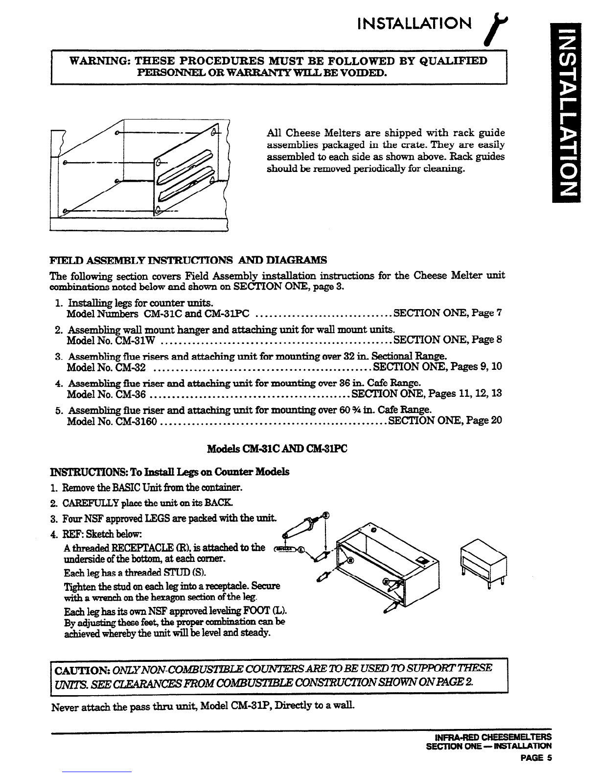
All Cheese Melters are shipped with rack guide
assemblies packaged in the crate. They are easily
assembled to each side as shown above. Rack guides
should be removed periodically for cleaning.
FIELD ASSEMBLY INSTRUCTIONS AND DIAGBAMS
The following section covers Field Assembly installation instructions for the Cheese Melter unit
combinations noted below and shown on SECTION ONE, page 3.
1. Installing legs for counter units.
Model Numbers CM-31C and CM-31PC . . . . ..*...-.................... SECTION ONE, Page 7
2. Assembliug wall mount hanger and attaching unit for wall mount units.
Model No. CM-31W .. . .. ...... . ... .. .. .. .. . . .. .. .. ... .. .... .. .. .. ... ...SECTION ONE, Page 8
3. Assembling flue risers and attaching unit for mounting over 32 in. Sectional Range.
Model No. CM-32 .. .. . . .. .. .. .. .. .. ...-........................... SECTION ONE, Pages 9,10
4. Assembling flue riser and attaching unit for mounting over 36 in. Cafe Range.
Model No. CM-36 .. .. .. . . .. .. ... . ... . . .. . . . . . . .. .. .. .. ... .... .SECTION ONE, Pages 11,X& 13
5. Assembling flue riser and attaching unit for mounting over 60 % in. Cafe Range.
Model No. CM-3160 .. . ..I............................................. SECTION ONE, Page 20
INSTRUCI’IONS: To Install Legs on Counter Models
1. Removethe BASICUnit from the container.
2. CAREFULLY placethe unit on its BACK.
3. Four NSF approvedLEGS are packedwith the unit.
4. REl? sketcllbelow
Atbreaded~CEPTACLE(R),isattacbedtothe
underside oftbe bottom, at eachcomer.
Eachleg has athreaded STUD (S).
‘I?ghtentbestudoneachlegintoareceptace.Secure
with awrenchonthehexagonsection
ofthe leg.
Eachleg hasits ownNSF approvedleveling FOOT (LX
By adjust&these feet,the proper combination can be
achievedwherebythe unit will belevel and steady.
Never attach the pass thru unit, Model CM3lP, Directly to a wall.
1NmA-REDcHEEsEMELlERs
SECTIONONE-INSTALLA= PAGE 5
\
INSTALLATION
1.
2.
3.
4.
5.
6.
7.
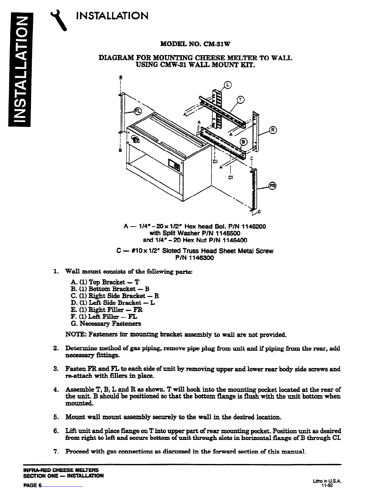
MODEL NO. CM31W
DIAGRAM FOR MOUNTING CHEESE MELTER TO WALL
USING CM-W-31 WALL MOUNT KIT.
%
A- l/4” -20 x l/2” Hex head Sol. P/N 1146200
with Split Washer P/N 1146500
and
l/4” -20 Hex Nut P/N 1146400
C - #10x 112” Sloted Truss Head Sheet Metal Screw
PIN 1146300
Wall
mouut consists of the following parts:
A.
(1)
Top Bracket - T
B. (1) Bottom Bracket - B
C. (1) Right Side Bracket - R
D.
(1) Left Side Bracket - L
E. (1) Right Filler - FR
F. WLeft Filler-FL
G. Necessary Fasteners
NOTE: Fasteners
for mounting
bracket
zttssembly to wall are
not provided.
Determine method of gas piping, remove pipe plug from unit and if piping fkom the rear, add
===wfittings.
Assemble T, B, L and R as showu. Twill
hook into the
mounting pocket located at the rear of
the unit. B should be positioned sothat the bottom flange is flush with the unit bottom when
lllOunted.
Mount wall mount assembly securely to the wall in the desired location.
Liftunit andplace~eonTiato~partafrearmountingpocket.Positionunit asdesired
fromrighttoleftalld secure bottom of unit through slots in horizontal flange ufB through CL
Rocf3ed with gas connections as discus& in the forward section of this mauual.
INFRARED CHEESE MELTERS
SECIION ONE - INsTc\LLATIoN
INSTALLATION I
WARNING: FOR AN APPLIANCE EQUIPPED WITH CASTERS, TRE INSTALTXf’ION
SHALL BE MADE WITB A CONNECTOR TEIAT COMPLIES WITH TEE STANDARD FOR
CONNECTORS FOR MOVABLE GAS APPLIANCES, ANSI
221.69-198‘7, CAN/CGA-6.16.
MS7 AND A
QUlCX-DISCONNECT DEVICE THAT COMPLIES WITH THE STANDARD
FOR
QUICK-DISCONNECT DEVICES FOR USE
WITH GAS FUEL, ANSI 221.41-1978,
AND
ADDENDA,
Z21.41a-1981, ZZ1.41b-1983 AND CAN1 6.9 M79. ADEQUATE MEANS
MUST BE PROVIDED TO IJMXT THE
MOVEMENT OF THE
APPLJANCE WITHOUT
DEPENDING ON THE CONNECTOR AND THE QUICK-DISCONNECT DEVICE OR ITS
ASSOCIATEDPIPlNGTOIJMITTFIEAPPLL4NCEMOVEMENT.
~iJlI?+I&ISCO.~~ON OF THIS REJ
STRAINT Is NECESSARY To REMOVE
CIZANING, EYI’C, RECONNECT IT WHEB TEIE APPIJANCE IS
MOVED TO ITS ORIGINALLY INSTALLED POSITION.
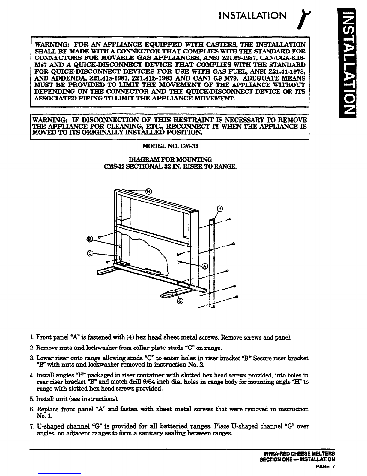
MODEL NO. CM-32
DIAGM FOR MOUNTING
CMS-32SECTIONAL32IN.RzsERTORANGE,
1. Front
panel “A” is fastened with (4) hex head sheet metal screws.Removescrewsand panel.
2.
Removenuts and lockwasher f+omcollar plate studs “C” on range.
3.
Lower riser onto range allowing studs “C” to enter holes in riser bracket ‘EV Secureriser bracket
%= with nuts and lockwasher removed in instru~on No. 2.
4. Install angles W packaged in riser container with slotted hez head screwsprovided, into holes in
rear riser bracket ‘W and match drill 964 inch dia. holes in range bodyfor mounting angle “IT to
range with slotted hex head screws provided.
5.
Install unit (see instnlctioIls).
6.
F&place fkont panel uA” and fasten with sheet metal screws that were removed in in&r&ion
No. 1.
7. U-shaped channel ‘G” is provided for all batteried ranges. Place U&aped channel ‘G” over
angles on adjacent ranges to form a sanitary sealing between ranges.
iNFRA-i?EDCHEESEMELTERS
sEcnoNoNE-lNsTALLAnoN
PAGE 7
INSTALLATION
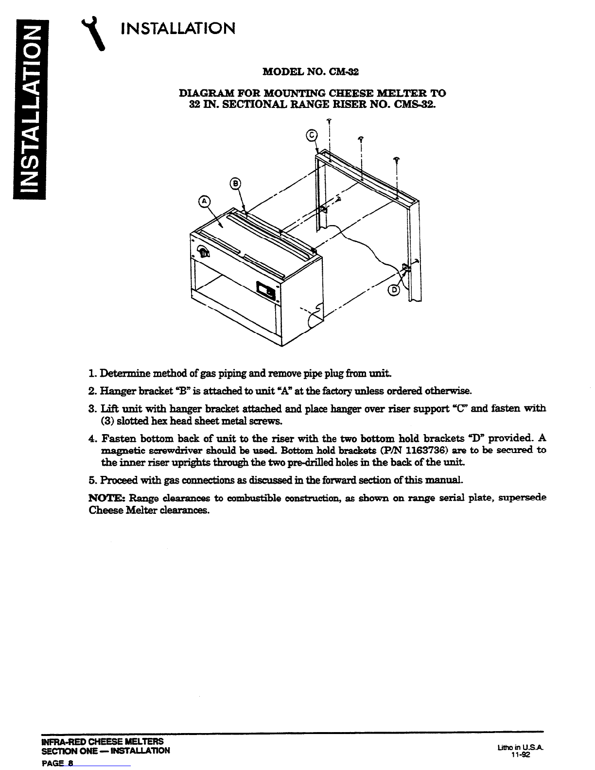
MODEL NO. CM-32
DIAGRAM FOR MOUNTING CHEESE MELTER TO
32 IN. SECTIONAL RANGE RJSER NO. CMS-32,
1. Determine method of gas piping and remove pipe plug fkomunit.
2. Hanger bracket “B” is attached to unit sA” at the &tory unless ordered otherwise.
3. Lift unit with hanger bracket attached and place banger over riser support “c” and fasten with
(3) slotted hex head sheet metal screws.
4. Fasten bottom back of unit to the riser with the two bottom hold brackets “D” provided. A
magnetic screwdriver should be used. Bottom hold brackets (P/N 1163736) are to be secured to
the inner riser uprights through the two prwlrilled holesin the back of the uniti
5.proceedwithgaswnnectiansasdiscussedinthefo~sectionofthismanual.
NOTE: Range clearances to combustible con&n&ion, as shown on range serial plate, supersede
Cheese Melter clearances.
INFRA-REDCHEESEMELTEFS
SECTlON ONE- WSTALLAllON T%Y -
PAGE 8
INSTALLATION r
WARNING FORANAPPUANCE EQUIP= WlTE CASTERS, TEE INSTWTION
SHALLBEMADEWITHACONNECTORTHATCOMPIJES WlTHTEESI!!ARDFOR
CONNECTORS FOR MOVABLE GAS APPIJANCES, ANSI 221.69-1987, CAN/CGA-6.16-
MI37 AND A QUICK-DISCONNECI’ DEVICE TEAT COMPLlEX3 WITH THE WANDARD
FOR QUICK-DISCONNECT DEVICES FOR USE WIl’!E GAS FUEL, ANSI 221.41-1978,
AND ADDEND& 221Ala-1981,221.41b-1983 AND CAN1 6.9 M79. ADEQUATE MEANS
MUST BE PROVIDED TO LIMIT THE MOVEMENT OF TEE APPLIANCE WITHOUT
DEPENDING ON TBE CO~CTOR AND TEiE QUICK-DISCONNECT DEVICE OR ITS
ASSOCIATEDPIPINGTOLIMITTEIEAPPLLWcEMOVEMENT.
WARNING:
IJ?DISCONNECTION OF TEIS RESTRAINT Is NEcIEssARY TOREMOVE
THE APPIJANCE FOR CLEANING,EI’C,RECONNECT~WHENTBEAPPIJANCEIS
MOVEDTOITSORIGINAU,YINSTALLEDPOSITION.
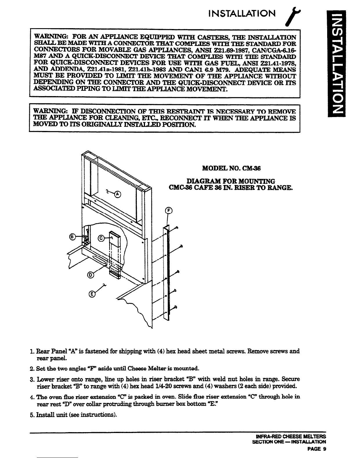
MODEL NO. CM=36
DIAGRAIKFORMOUNTING
CMCX6 CAFE 36 IN. RISER TO RANGE.
1.Rear Panel *A” is fastened far shipping with (4) hex head sheet metal screws. Removescrews and
rear panel,
2. Set the two angles T’ aside until CheeseMelter is mounted.
3. Lower riser onto range, line up holes in riser bracket “B” with weld nut holes in range. Secure
riser bracket ‘W’ to range witb (4) hex head l/4-20 screws and (4) washers (2 each side) provided.
4.
The oven flue riser extension T” is packed in oven. Slide fiue riser extension 7.7 t&rough hole in
rear rest “IIn over collar protruding tbrougb burner box bottom YE.”
5.Install unit bee instnlctions).
WFFiA-REDCHEESEMELTERS
sEclloNoNE-!lNsTAuATloN PAGE 9
\
1.
2.
3.
4.
5.
INSTALLATION
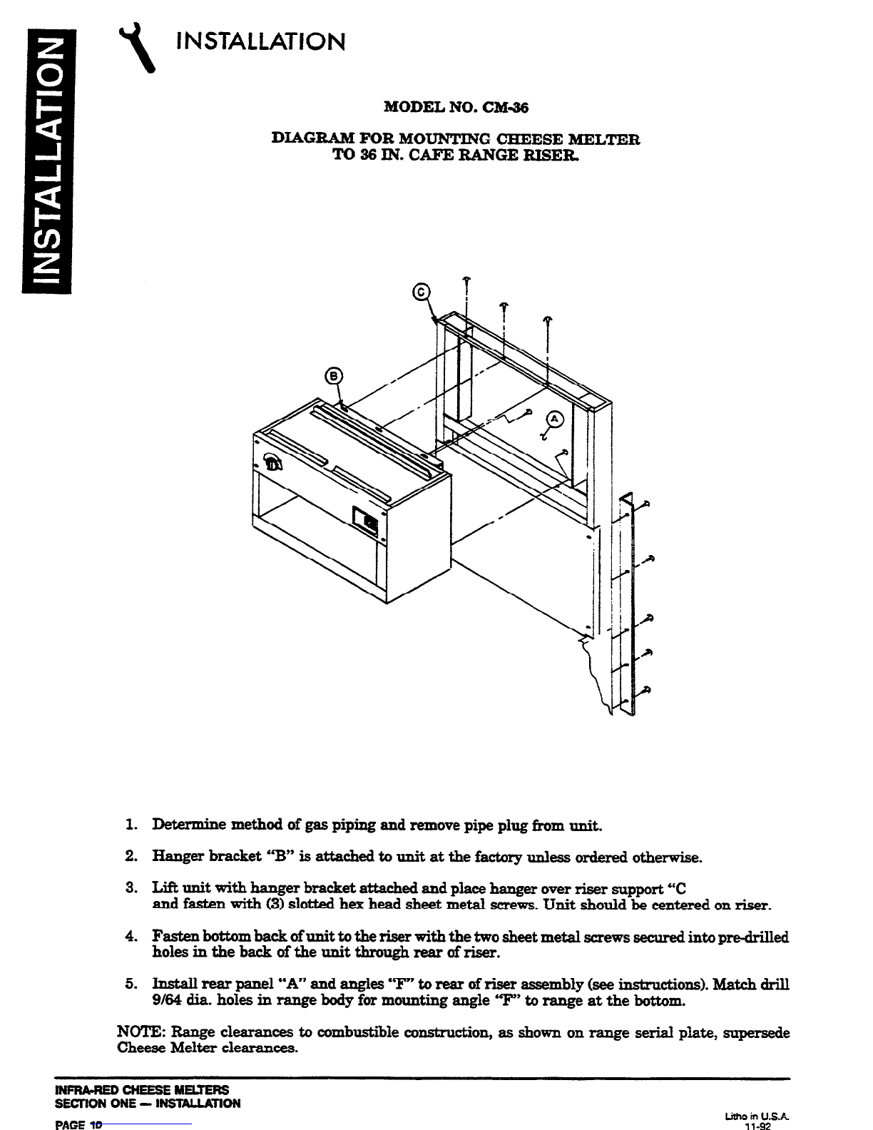
MODEL NO. CM36
DIAGRAM FOR MOUNTING CHEESE MELTER
To 36 IN. CAFE RANGE RISER.
Determine method of gas piping and remove pipe plug from unit.
Hanger bracket “B” is attached to unit at the factory unless ordered otherwise.
Lift unit with hanger bracket attached and place hanger over riser support “C
and fasten with (3) slotted hex head sheet metal screws. Unit should be centered on riser.
FastenbottombaclrofunittotheFiserwiththetwosheet metalscrewssecuredintopredrilled
holesintheb~oftheunitthroughrearofriser.
Install rear panel “A” and angles “‘I”’ to rear of riser assembly (seeinstructions). Match drill
9164 dia. holes in range body for mounting angle 9” to range at the bottom.
NOTE: Range clearances to combustible cons&u&ion, as shown on range serial plate, super&e
Cheese Melter clearances.
lNPRA=NEDcNEEsEMEuEFls
SECTION ONE - INsTAuATlON

INSTALLATION
t
MODEL NO. CM36
DIAGRAM FOR INSTALUl4G REAR PANEL AND ANGLES
AFlXR CHEESE METLER IS MOUNTED TO 36 IN. CAFE RANGE RISER.
1. Install rear panel “A” and an&s ‘T” to rear ofriser assembly with screw locations shown. Match
drill 9164dia. holes where needed in riser and range body.
2. Proceed with gas connections as discus& in the forward section of this manual.
INFfWREDCHEESEMEUERS
SIWION ONE- lNSKALLKllON
I
INSTALLATION
FIELD ASSEMBLY INSTRUCZ’IONS AND DIAGRAMS
The following section covers Field &sembly in&al&ion instructions for the CheeseMelter unit com-
binations noted below and shown on SECTION I, page 3.
1. Installing legs for counter units.
Model Numbers CM-GOCand CM-GOPC SECTION I, page 14
2. Assembling wall mount hanger and attaching unit for wall mount units.
Model No. CM-GOW . . . . . . . . . . . . . . . . . . . . . . . . . . . . . . . . .. . . . . . . . . .SECTIONI, page 15
3. Assembling flue riaors and attaching unit for mounting over two 64 in. Sectional Ranges.
Model No. CM-64 . . . . . . . . . . . . . . . . . . . . . . . . ..
. . . . . . . . . . . . . . .SECTION I,
pages 16, 17
4.
Assembling flue risor and attaching unit for mounting over 60-314in. Cafe Range.
Model No. CM-60-60. . . . . . . . . . . . . . . . . . w. . . . . . . . . . . . . . . . . . .-SECTION I, pages 18,19
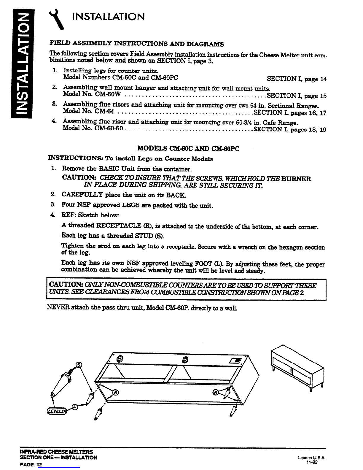
MODELS CM-6OC AND CM-PC
INSTRUCTIONS: To instaII Legs on Counter Models
1. Remove the BASIC Unit from the container.
CAUTION:
C~CKTOlNSVRE THAT THESCREWS, WHICHHOLD
=BURNER
I.N PLACE DURING SILlPPmG, ARE STILL SECURlNG IT.
2. CAREFULLY place the unit on its BACK.
3. Four NSF approved LEGS are packed with the unit.
4.
REFz Sketch below:
A threaded RECEPTACLE CR),is attached to the underside of the bottom, at each comer.
Each leg has a threaded STUD Q.
Tighten the stud on each leg into a receptacle. Secure with a wrench on the hexagon section
of the leg.
Each leg has its owp NSF approved leveling FOOT (L). By ad.. these feet, the proper
combination can be achieved whereby the unit will be level and steady.
CAUTION: ONLYNON~OMBU co-AREmBEusEDmsuPmm~
lIlM!ls..
~~~OMooMBUslzBLE~U~ONsHow1vONPAGE2.
NEVER attach the pass tbru unit, Model CM-GOP,directly to a wall.
WFRA-RED CHEESE MELTERS
SECTIONONE-lNSTALUllON
PAGE 12
1.
2.
3.
4.
5.
6.
7.
INSTALLATION
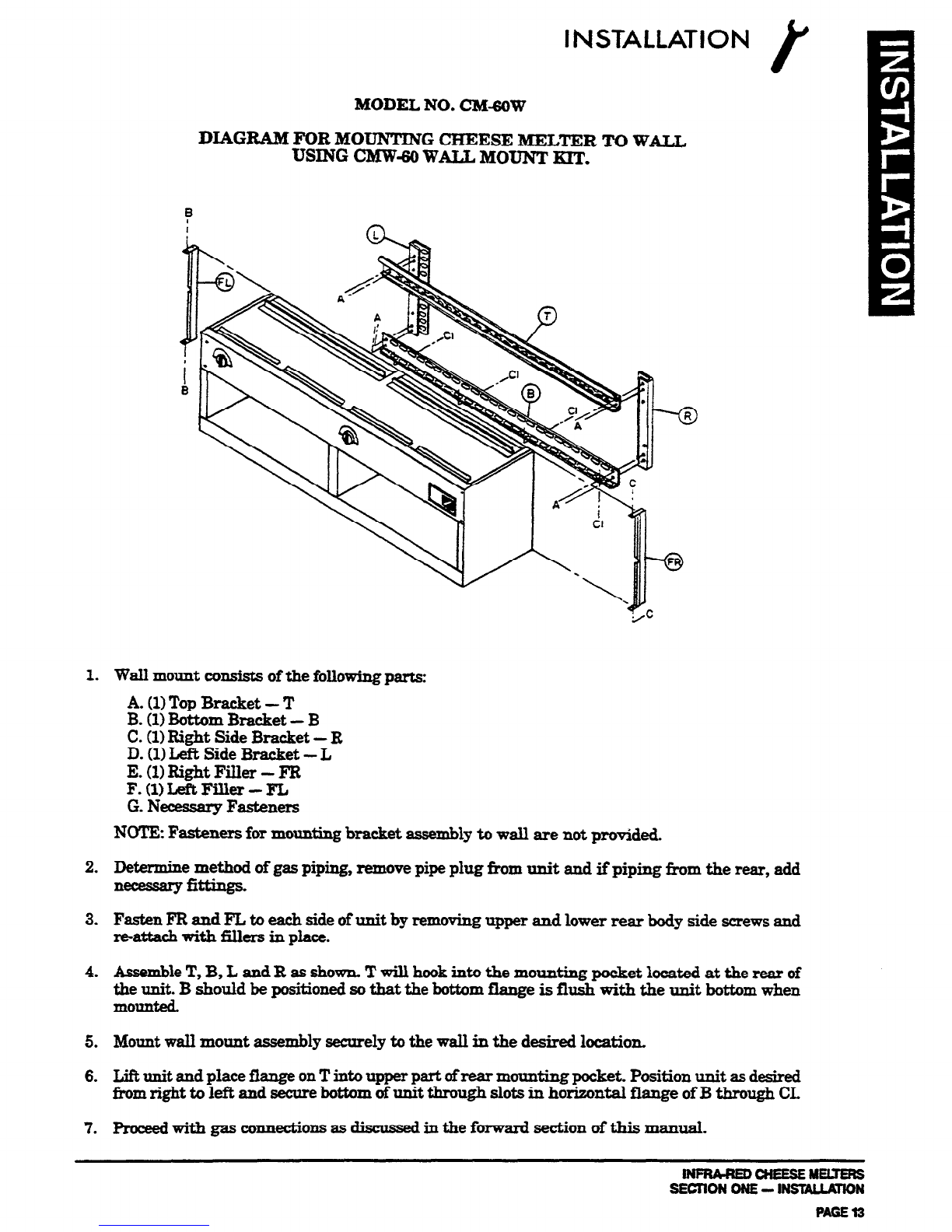
MODEL NO. CM&oW
DIAGRAM FOR MOUNTING CHEESE MELTER TO WALL
USING CMWa WALL MOUNT EXT.
Wall mount consists of the
following
parts:
A. (1)Top Bracket - T
B. (1)Bottom Bracket - B
C. (1)Right Side Bracket - B
D. (1)Left Side Bracket - L
E. (1)Right Filler - FR
F.WLeft.Filler-FL
G.Necessary Fasteners
NOTE Fasteners for mounting bracket assembly to wall are not provided.
Determine method of gas piping, remove pipe plug from unit and if piping from the rear, add
necessargfittings.
Fasten FR and FL to each side of unit by removing upper and lower rear body side screws and
*attach with fillers in place.
AssembleT, B, L and R as shown. T will hook into the mounting pocket located at the rear of
the unit. B should be positioned so that the bottom flange is flush with the unit bottom when
mounted.
Mount wall mount assembly securely to the wall in the desired location.
Lift
unit
and place flange on T into upper part ofrear mounting pocket. Position
unit
asdesired
from right to left and secure bottom of unit through slots in horizontal flange of B through CL
proceedwith gas ccmmctions as discus& in the forward section of this manual.
lrmuaEDcNEEsEMEuENs
SECTION ONE-INSlUJJlON
PAGE13
1
INSTALLATION
WARNING FOR AN APPIlLGNcE EQUIPPED WITH CASTERS, THE INSTALLATION
SHALT., BE MADE WITH A CONNECTOR TEAT COMPLIES WITH THE STANDARD
FOR CONNECTORS FOR MOVABI;E GAS APPLIANCES, ANSI 221.69-1937, CAN/CGA-
6.16-MS7 AND A QUICK-DISCONNECT DEVICE THAT COMPLIES WITH THE
STANDARD FOR QUICK-DI!XONNECT DEVICES FOR USE WlTH GAS FUEL, ANSI
221.41-1978, AND ADDENDA, 221.41a-1981, Z21.41b-1983 AND CAN1 6.9 M79.
ADEQUATE MEANS MUST BE PROVIDED TO LIMIT THE MOVEMENT OF THE
APPLIANCE WITHOUT DEPENDING ON THE CONNECTOR AND THE QUICK-
DISCONNECT DEVICE OR ITS ASSOCIATED PIPING TO LIMIT THE APPLIANCE
MOVEMENT.
WAR&IN& IF DISCONNECTION OF THIS RESTRAINT Is NECESSARY To REMOVE
TBE APPLTANCE FOR tXZANlNG, E’IC, RECONNECT IT WHEN THE APPLIANCE IS
MOVED TO ITS ORIGINALLY INSTALLED POSITJON.
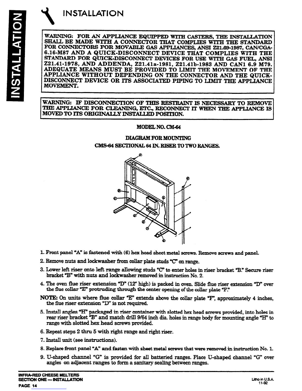
MODEL NO. CM-64
DIAG.&iMFORIKOUNTING
cMs-64sEcTIoNAL64lN.RI8ERToTwoRANGEs
1. F’ront panel “A” is fastened witb (6) hex head sheet metal screws.Remove screws and paneL
2. Removenuts and lockwasher fkom collar plate studs T’ on range.
3. Lower left riser onto lefk range allowing studs ‘C to enter holes in riser bracket ‘B.” Secure riser
bracket “B” with nuts and lockwaaher removed in instruction No. 2.
4. The oven flue riser extension “D” (12” high) is packed in oven.mde flue riser extension “I)” over
the flue collar T protruding through the center opening ofthe collar plate T.=
NOTE: On units where flue collar T’ extends above the collar plate T’, approximately 4 inches,
the flue riser extension UD” is not required.
5. Install angles w” packaged in riser container with slotted hex head screws pn>vided,into holes in
rear riser bracket 3” and match drill 9164inch dia. holes in range body for mounting angle “H” to
range with slotted hex head screws provided.
6. Repeat steps 2 thru 5 with right range and right riser.
7. Install unit (see instnlctions).
8. Replacefront panel “A” and fasten with sheetmetal screwsthat were removed in iu&uction No. 1.
9. U-shaped channel “G” is provided for all battexied ranges. Place U-shaped channel ‘G” over
angles on adjacent ranges to form a sanitary sealing between ranges.
INFRA-REDCHEESEMELTERS
SECTlOHOHE-IHSTALLATiOH
PAGE 14
litho in U.SA
11-92
INSTALLATION r
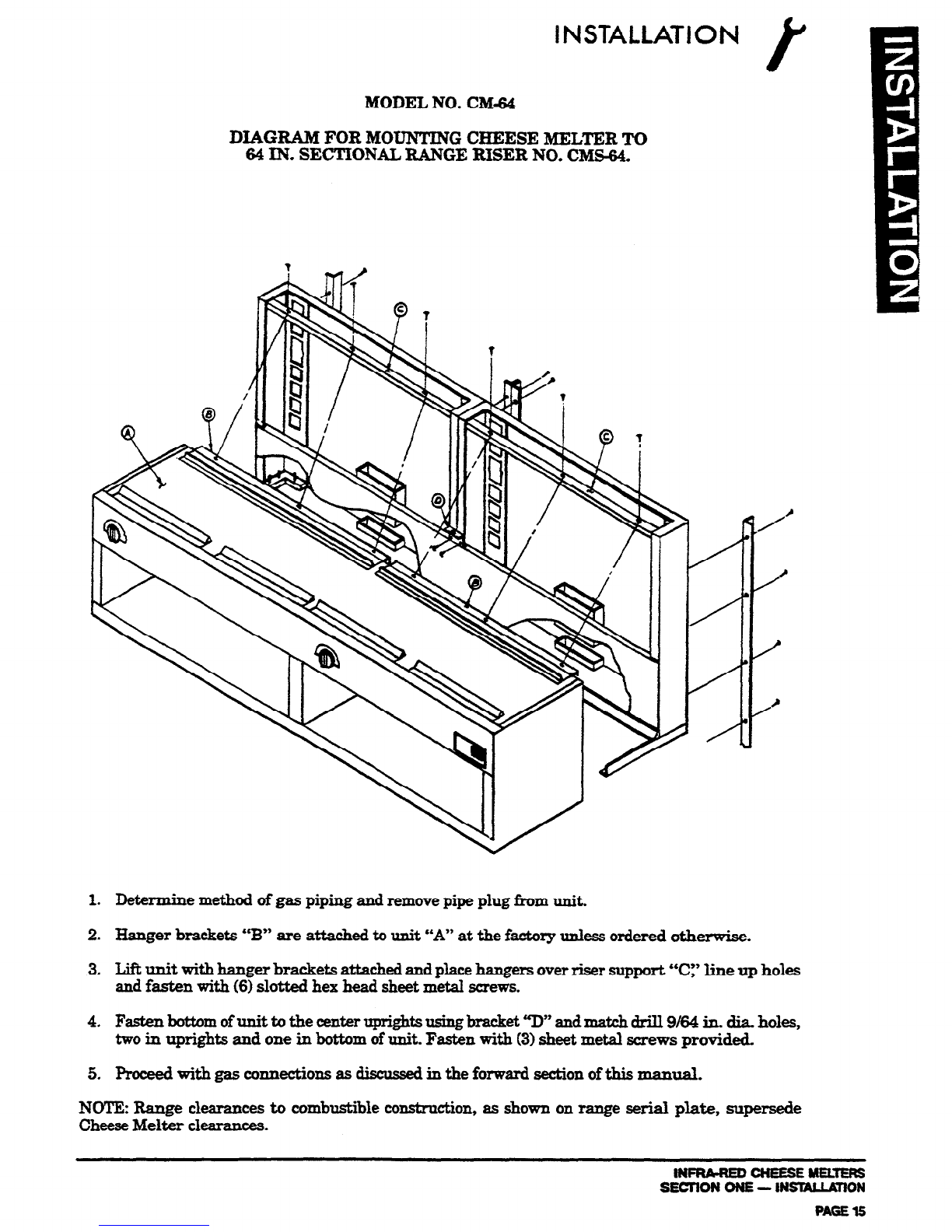
MODEL NO. CM&$
DIAGRAM FOR MOUNTING CHEESE MELTER TO
64 IN. SECTIONAL RANGE RISER NO. CMS-64.
1. Determine method of gas piping and removepipe plug from unit.
2.
Hanger brackets “B” are attached to unit ‘A” at the factoq unless ordered otherwise.
3. LiR unit witi banger brackets attached and placehangers overriser support “Cy line up holes
and fasten with (6) slotted hex head sheet metal screws.
4.
Fasten bottom ofunit to the center uprights using bracket ‘p,t andmatch drill 9164in. dia. holes,
two in uprights and one in bottom of unit. Fasten with (3)sheet metal screws provided.
5. Proceed with gas connections as discus& in the forward section of this manual.
NOTE: Range clearances to combustible constmction, as shown on range serial plate, supersede
CheeseMelter clearances.
INPNA-NED CNEESE hELtENS
SECnON ONE - INSULLUION
PAGE 15
I
INSTALLATION
WARNING FORANAPPLIANCE EQUtPPED WITTI CASTERS, THE INST~TION
SHALL BE MADE WITH A CONNECTOR THAT COMPLIES WITH THE STANDARD
FOR CONNECTORS FOR MOVABLE GAS APPLIANCES, ANSI 221.69-1987, CAN/CGA-
6.16-MS7 AND A QUICK-DISCONNECT DEVICE THAT COMPLIES WITH THE
STANDABD FOR QUICK-DISCONNECT DEVICES FOR USE WITH GAS FUEL, ANSI
221.41-1978, AND ADDENDA, 221.41a-1981, 221.41b-1983 AND CAN1 6.9 M79.
ADEQUATE MEANS MUST BE PROVIDED TO LIMIT THE MOVEMENT OF TH.E
APPLIANCE WITHOUT DEPENDING ON THE CONNECTOR AND THE QUICK-
DISCONNECT DEVICE OR ITS ASSOCLATED PIPING TO LIMXT THE APPLIANCE
MOVEMENT.
WARNING IF DISCONNECTION OF THIS RESTRAINT Is NECESSARY To BEMOVE
THEAPPLk3NCEFOR CLEANING, El-C., RECONNECT IT WHEN THE APPLIANCE IS
MOVED To ITS OBIGINALLY YNSTATXXD POSITION.
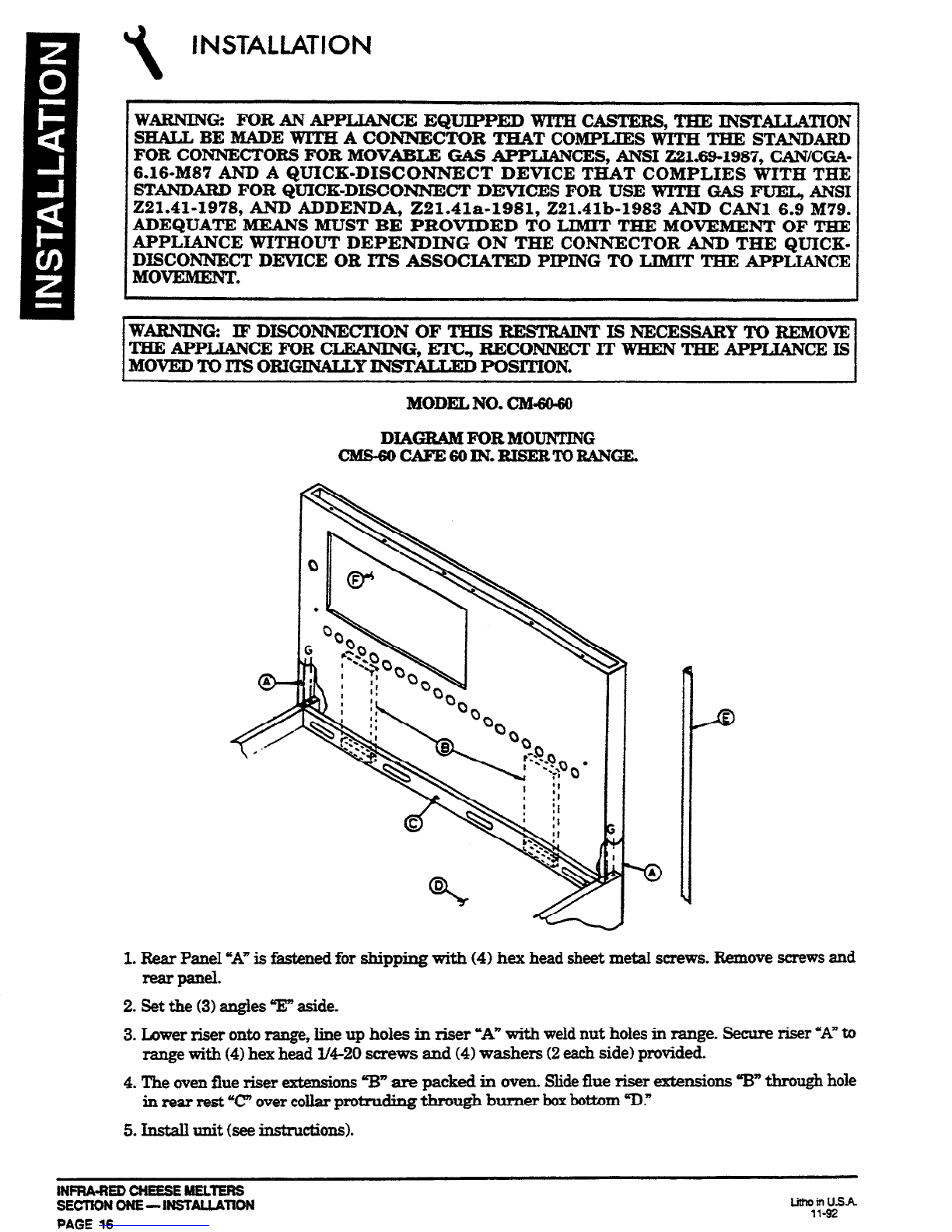
MODELNO. CM&60
DIAGR&IFORMOUN’lJNG
ClKS=6OCAFE6OlN..TORANBANGE.
1.Rear Panel “A” is fastened for sbipping with (4) hex head sheet metal screws. Remove screws and
rear panel.
2. Set the (3) angles “E” aside.
3. Lower riser onto range, line up holes in riser “A” with weld nut holes in range. Secure riser “A” to
range with (4) hex head M-20 screws and (4) washers (2eachside) provided.
4. The ovenflue riser extensions “B” are packed in oven. Slideflue riser extensions ‘W through hole
in rear rest “CT’over collar protrucling through burner boxbottom “II.”
5. Install unit (seeinstrllctions).
INFRA-REDCHEESEMELTERS
SECTION ONE- 1NSTALLATlON
PAGE
16
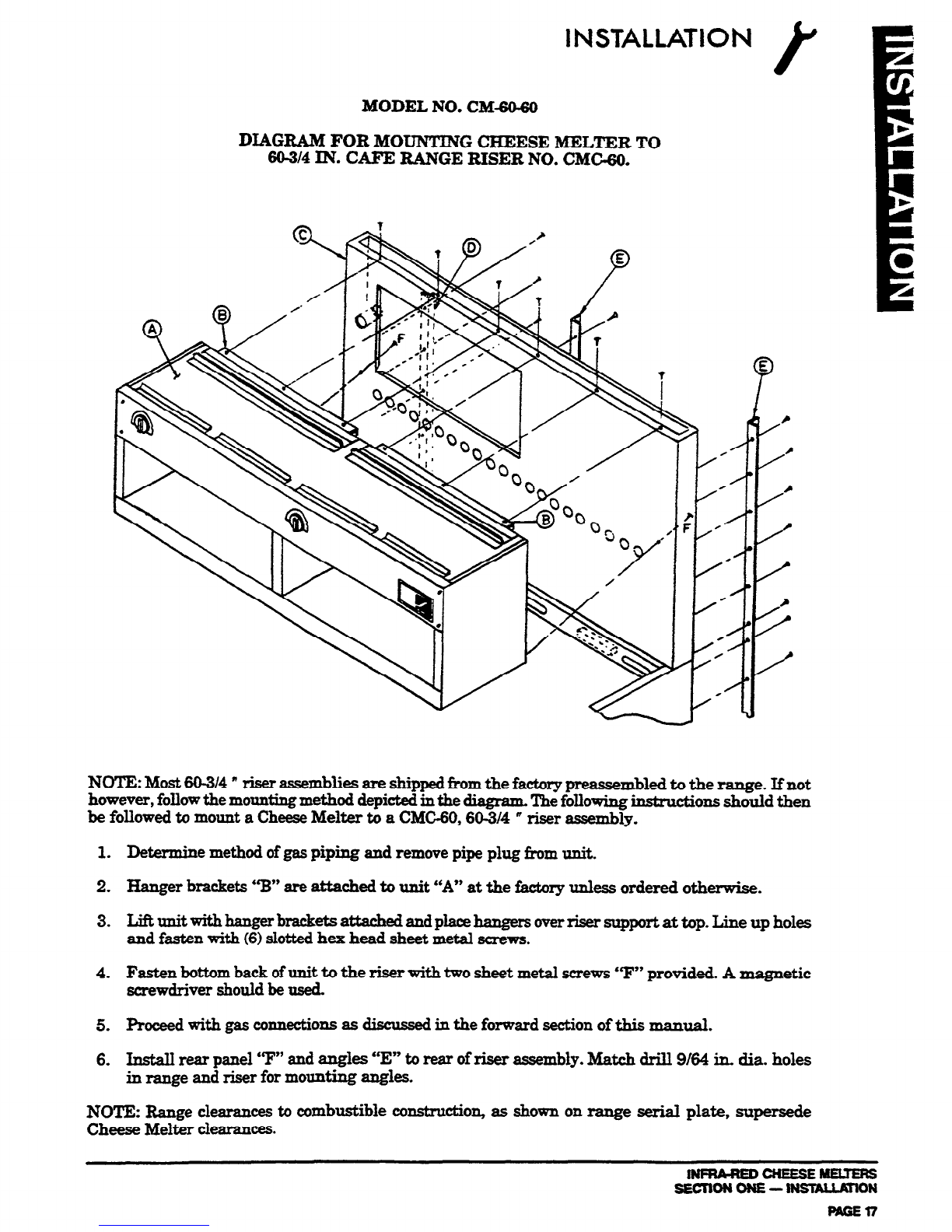
MODEL NO. CM-6@60
DIAGRAM FOR MOUNTING CHEESE MELTER TO
60-314
IN. CAFE RANGE RISER NO. CMCXo.
NOTE: Most 60-314* riser assemblies are shipped &om the factory preassembled to the range. If not
however, follow the mounting method depicted in the diagram Thefollowing in&n&ions should then
be followed to mount a CheeseMelter to a CMG60,60-3/4 ” riser assembly.
1. Determine method of gaspiping and remove pipe plug from unit.
2. Hanger brackets “B” are attached to unit “A” at the f&tory unless ordered otherwise.
3. Lift unit with hanger brackets attached and placehangers overriser support at top. Line up holes
and
fasten
with (6)slotted hex head sheet metal screws.
4. Fasten bottom back ofunit to the riser with two sheet metal screws ‘9” provided. A magnetic
screwdriver should be used.
5. Roceed with gas connections as discussedin the forward section of this manual.
6. Install rear panel ‘9” and angles “E” to rear of riser assembly. Match drill 9/64 in. dia. holes
in range and riser for mounting angles.
NO!I’E: Range clearances to combustible construction, as shown on range serial plate, supersede
Cheese Melter clearances.
INRU-REDCHEESEMEUEF&
SECTIONONE--ON MGEn

\
INSTALLATION
WARNING FORANAPPLIANCE EQUIPPED WITH CASTERS, THE INSTALLA~ON
SHALL BE MADE WITH A CONNECTOR THAT COMPLIES WITH THE STANDARD
FOR CONNECTORS FOR MOVAEIZ GAS APPIZANCES, ANSI
221.69-1987,
CAN/CGA-
6.16-MS7
AND A QUICK-DISCONNECT DEVICE THAT COMPLIES WITH THE
STANDARD FOR QUICK-DISCONNECT DEVlCES FOR USE WITH GAS FUEL, ANSI
221.41-1978,
AND ADDENDA,
221.41a-1981, 221. 4133-1983 AND CAN1 6.9 M79.
ADEQUATE MEANS MUST BE PROVIDED TO LIMIT THE MOVEMENT OF THE
APPLblNCE WITHOUT DEPENDING ON THE CONNECTOR AND THE QUICK-
DISCONNECT DEVICE OR ITS ASSOCIATED PIPING TO LIMIT THE APPLIANCE
MOVEMENT.
WARNING: IF
DISCONNECTION OF T[lBIs ZtEsTRAINT Is NECESSARY To REMOVE
THE APPLTANCE FOR CLEANING, ETC., RECONNECT IT WHEN THE APPLIANCE IS
MOVED TO ITS ORXGlNALLY IWTALLED
POSITION.
MODEL NO. CM-31.60
DIAGRAB5FORMOUNTINGCEERSEMELTERTO
6@3/4IN. CAFE RANGE RISER NO. MRK-30.
NOTE: Most 60-3/4” riser assemblies are shipped from the factory preassembled to the range. Ifnot
however, foIlow the mounting method depicted in the diagram. The following instructions should
then be followed to mount a Cheese Melter to a MRK-30,60-3/4” riser assembly.
1.Determine method of gaspiping and remove pipe plug from unit.
2.
Hanger bracket “B” is attached to
unit
“A” at the factory unless ordered otherwise.
3.
Lift unit with hanger bracket attached and place hanger over riser support at top. Line up holes
and fasten with (3) slotted hex head sheet metal screws. Unit should be flush against shelf.
4.
Fasten
bottom back of unit to the riser with two bottom hold brackets “c” provided. A magnetic
screwdriver should be used. Bottom hold brackets (P/N 1163736) are to be secured to izmer
riser
uprights through the two pre-drilled holes in the back of the unit.
5. Proceedwith gas connections as discussed in the forward section of this manual.
NOTE: Range clearances to combustible con&n&ion, as shown on range serial plate, supersede
CheeseMelter clearances.
lNFRh-REDCNEESEMELTEFlS
SECTION ONE- INSlALLATlON
PAGE $8 ““l%iSA
This manual suits for next models
14
Table of contents
Other Southbend Kitchen Appliance manuals

Southbend
Southbend HDO-12 User manual

Southbend
Southbend BEMTS-30 User manual

Southbend
Southbend BECT-24 User manual

Southbend
Southbend GCX-2-6 User manual

Southbend
Southbend P32-CM User manual

Southbend
Southbend RAPIDSTREAM R2 User manual

Southbend
Southbend P24-CM User manual

Southbend
Southbend StratoSteam STRG-3D User manual

Southbend
Southbend EZ24-3 User manual

Southbend
Southbend RG24-5 User manual


