Speco CVC230HZ User manual

OPERATION / INSTALLATION MANUAL
200 New Highway, Amityville, NY 11701
www.specotech.com
!Speco Technologies is constantly developing product improvements.
We reserve the right to modify product design and specifications
without notice and without incurring any obligation. Rev. 4/28/10

The lightning flash with an arrowhead symbol, within an
equilateral triangle is intended to alert the user to the presence
of uninsulated dangerous voltage within the product’s enclosure
the may be of sufficient to constitute a risk of electric shock to
persons.
The exclamation point within an equilateral triangle is intended
to alert the user to the presence of important operating and mai
ntenance (servicing) instructions in the literature
accompanying the appliance.


1) Camera mounting screw hole
2) Camera mounting screw hole
Back
3) Key Buttons
4) Power LED
5) Video Output Jack
6) RS-485
9) Power Input Terminal
8) Communication Control Connector
7) External Control
Connector

: To Move the arrow indicator to up.
: To Move the arrow indicator to down.
: To Move the arrow indicator to left.
: To Move the arrow indicator to right.
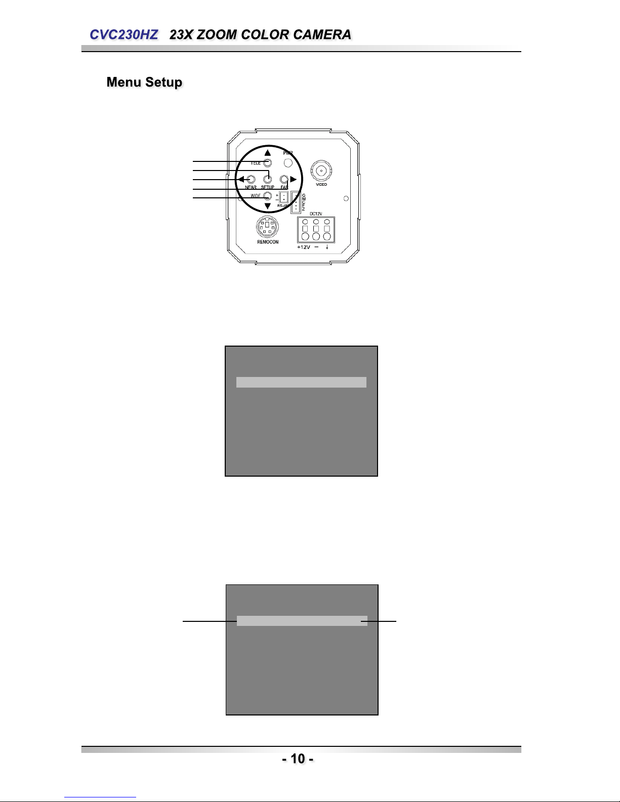
Main setup menu can be navigated using these buttons.
SET : To access the main setup menu.
UP (WIDE button)
Down (TELE button)
LEFT ( F-NEAR button)
RIGHT (F-FAR button)
*The zoom position is saved after 5 seconds when you set zoom function.
4. Power LED
Illuminates when power is supplied.
5. Video Output Jack
Used to connect an external video monitor in jack.
6. RS-485
Includes the RS-485 communication pin
1. Top Mounting Bracket Screw Hole
Used to fix tripod mounting bracket on top of the camera.
2. Tripod Mounting Hole
Used to install the camera on an optional tripod.
The tripod must be equipped with screws with specifications
shown on the right.
3. Key Buttons
Following buttons control zoom, focus, and auto focus functions.
WIDE button
TELE button
F-NEAR button
F-FAR button
AF button
Pressing the ‘SET’ button locks the zoom control function of
these buttons and prompts the main setup menu.
: To widen the view. (ZOOM OUT)
: To close in on a far object. (ZOOM IN)
: To see a near object clearly.
: To see a far object clearly.
: To activate auto focus just once.

7. External Control connector
Relaters to the motion detection output signal.
Zoom and focus functions can be controlled using external
signals.
8. Communication Control Connector
Used to connect the Remote Controller (Option).
9. Power Input Terminal
Power supply terminal
+ Connection methods may vary depending on the video equipment.
Please refer to the model specific instruction manual.
+ Connect cables with the unit powered down.
+ Set the 75Ω/ Hi-Z selection switch as shown below if you have an
intermediate device.
75ΩHi-Z 75ΩHi-Z

2) Connecting to Power
Each model has a different power input specification.
Please check the model type and standard power requirement before connecting to power.
+ Communication Control Connector Pin Description.
NumberNameNumberName
1Right4Auto Focus
2Left5Down
3Setup6Up

MAIN SETUP MENU
RESET
EXIT
MOTION DET OFF
FOCUS MODE
ZOOM SPEED
DISP ZOOM MAG
LENS INIT
ZOOM TRK
D-ZOOM
ZOOM POS INIT
END
EXPOSURE BRIGHTNESS
AGC
END
IRIS
SSNR
SHUTTER
SENS-UP
WHITE BALANCE ATW(OUTDOOR) MANUAL
AWCSET
BACKLIGHT OFF
HIGH
MIDDLE
LOW
CAM TITLE OFF ON
SPECIAL USER PRESET
DAY/NIGHT
COMM ADJ
PRIVACY
DIS SYNC
END
IMAGE ADJ

Up button
SET button
LEFT button
RIGHT button
DOWN button
Use the six buttons on back of the camera
1. Press the SET button to access the main setup mode.
- Main setup menu is displayed on the monitor screen
MAIN SETUP
CAM TITLE
WHITE BAL
BACKLIGHT
MOTION DET
FOCUS
EXPOSURE
SPECIAL
RESET
EXIT
OFF
ATW
OFF
OFF
▶
◀┘
◀┘
◀┘
◀┘
2. Select the desired feature using the UP or DOWN button.
- Each pressing of the UP or DOWN button moves the indicator to the nest or previous
feature.
- Move the arrow indicator to the desired feature item.
MAIN SETUP
CAM TITLE
WHITE BAL
BACKLIGHT
MOTION DET
FOCUS
EXPOSURE
SPECIAL
RESET
EXIT
OFF
ATW
OFF
OFF
▶
◀┘
◀┘
◀┘
◀┘
Select feature
using the UP
or DOWN button.
Change the status
using the LEFT
or RIGHT button.

3. Change the status of the selected feature using the LEFT or RIGHT button.
4. When completed, move the arrow indicator to ‘EXIT’ and press the SET button.
Use this feature to designate a name for the camera, which will display on the
monitor screen.
1. Press the SET Button to display the main setup menu and move the arrow indicator to
‘CAM TITLE’ using the UP or DOWN button.
2. Set ‘CAM TITLE’ to ‘ ON’ using the LEFT or RIGHT button.
MAIN SETUP
CAM TITLE
WHITE BAL
BACKLIGHT
MOTION DET
FOCUS
EXPOSURE
SPECIAL
RESET
EXIT
OFF
ATW
OFF
OFF
▶
◀┘
◀┘
◀┘
◀┘
3. Press SET button.
CAM TITLE SETUP
ABCDEFGHIJKLMNO
PQRSTUVWXYZabcd
efghijklmnopqrs
Tuvwxyz01234567
89( ) < > - / # ! ? , .
CLR POS END

4. You can enter up to 20 characters.
1) Move the cursor to the character entry field using the LEFT or RIGHT button.
2) Use UP, DOWN, LEFT, and RIGHT buttons to select a desired character.
CAM TITLE SETUP
ABCDEFGHIJKLMNO
PQRSTUVWXYZabcd
efghijklmnopqrs
Tuvwxyz01234567
89( ) < > - / # ! ? , .
CLR POS END
3) Press the SET button to confirm selection of the blinking character. The character is
then saved, and the cursor in the entry field moves to the next position.
4) Repeat steps 1) through 3) until the desired name has been entered.
5. Select on screen position of the CAM TITLE.
1) Move the cursor to ‘POS’ and press SET button.
CAM TITLE SETUP
ABCDEFGHIJKLMNO
PQRSTUVWXYZabcd
efghijklmnopqrs
Tuvwxyz01234567
89( ) < > - / # ! ? , .
CLR POS END
2) The CAM TITLE is displayed on the top-left of the monitor screen.
(Default position)
3) Select the position by using the 4-directional buttons, then press the SET button to confir
m
the position.
6. When completed, move the cursor to ‘END’ and press SET button.

Your camera provides three ‘WHITE BAL’ control modes for your choosing in
Adjusting the white balance.
1. Press the SET button to access the main setup menu and move the indicator to ‘WHITE BAL’
using the UP or DOWN button.
2. Set ‘WHITE BAL’ using the LEFT or RIGHT button.
MAIN SETUP
CAM TITLE
WHITE BAL
BACKLIGHT
MOTION DET
FOCUS
EXPOSURE
SPECIAL
RESET
EXIT
OFF
ATW
OFF
OFF
▶
◀┘
◀┘
◀┘
◀┘
The three white balance control modes are as follows :
◈ATW (Auto Tracking White Balance) :
- OUTDOOR : This mode can be used within the color temperature
range 1,800~10,500K
(Ex: fluorescent light, outdoor, sodium vapor lamp or inside tunnels)
- INDOOR : This mode can be used within the color temperature range
3,000K~10,500K
◈AWC (Auto White balance Control) :
The white balance is automatically adjusted in a specific environment. In
order to obtain the best result, press the SET button while the camera
focuses
◈Manual :
To fine adjust, select the Manual mode. You can increase or decrease
the red or blue factor while monitoring the difference on the screen. Set to
‘MANUAL’ mode and press the SET button. Increase or decrease the
value for red (R-Gain) and blue (B-Gain), watching the color of the picture,
and press the SET button when you obtain the best color.

When there is a strong backlight behind the object, clear images of the
background as well as the object can still be obtained by using the BACKLIGHT
function.
1. Please position the arrow to point to ‘BACKLIGHT’ on the SETUP menu by using the UP
and DOWN buttons.
2. Please select the mode you wish to operate by pressing the LEFT or RIGHT button.
MAIN SETUP
CAM TITLE
WHITE BAL
BACKLIGHT
MOTION DET
FOCUS
EXPOSURE
SPECIAL
RESET
EXIT
OFF
ATW
OFF
OFF
▶
◀┘
◀┘
◀┘
◀┘
◈HIGH/MIDDLE/LOW: You can adjust the sensitivity of Backlight Compensation.
◈OFF: BACKLIGHT function does not operate.
This product has a feature that allows you to observe movement of objects in
4 different areas on the screen, and the words ‘MOTION DETECTED’ appear o
n the screen when movement is detected; hence a single individual can condu
ct supervision efficiently, The camera detects an object’s movement by sensing
disparity of outline, and level of brightness and color. The camera receives det
ection signal from MD output terminal.
MD SETUP
DISP ALARM
AREA SEL
AREA MODE
TOP
BOTTOM
LEFT
RIGHT
END
OFF
AREAL
ON
10
50
10
50
▶
IIIIIIIIIIIIIIIIII
IIIIIIIIIIIIIIIIII
IIIIIIIIIIIIIIIIII
IIIIIIIIIIIIIIIIII

+ Please press the SETUP button.
- OFF : MOTION DETECTION mode is cancelled.
- ON : Any motion in the selected areas is observed.
+ Please press the SETUP button.
- OFF : MOTION DETECTION mode is cancelled.
- ON : Any motion in the selected areas is observed.
+ Please select the area you wish to observe from the 4 areas in AREA SEL
mode.
+ Please select ON mode for the chosen area.
+ Please adjust the size of the area to be observed by using the UP, DOWN,
LEFT or RIGHT button.
+ Please press the SETUP button to save changes and complete the setting.
1. Press the SET button to access the main setup menu and then position
the indicator over FOCUS using the UP or DOWN button.
2. Press the SET button.
MAIN SETUP
CAM TITLE
WHITE BAL
BACKLIGHT
MOTION DET
FOCUS
EXPOSURE
SPECIAL
RESET
EXIT
OFF
ATW
OFF
OFF
▶◀┘
◀┘
◀┘
◀┘
MODE: You can select the most suitable zoom mode. Move the arrow
indicator to ‘MODE’ using UP or DOWN button.
FOCUS SETUP
MODE
ZOOM TRK
ZOOM SPEED
D-ZOOM
DISP ZOOM MAG
ONE-PUSH
ON
FAST
OFF
ON
▶◀┘
+ AUTO: Select auto and press the SET button to confirm. Increase or decre
ase optical zoom (ZOOM) or digital zoom (D-ZOOM) positions usin
g the UP or DOWN button while verifying the changes on screen. E
nabling D-ZOOM(ON) means that digital zoom will activate once op
tical zoom ends. Focus is automatically adjusted with moving zoom.

FOCUS SETUP
MODE
ZOOM TRK
ZOOM SPEED
D-ZOOM
DISP ZOOM MAG
ONE-PUSH
ON
FAST
OFF
ON
▶
◀┘
+ ONE PUSH: Focus is automatically adjusted just once, after zoom position is
changed. Select ‘ONE PUSH’ and press the SET button to conf
irm. Increase or decrease optical zoom (ZOOM) or digital zoom
(D-ZOOM) positions using the directional buttons while verifying
the changes on screen. Press the SET button once desired ima
ge quality is obtained.
+ MANUAL: Select ‘MANUAL’ and press the SET button to confirm. Increase
or decrease optical zoom (ZOOM) or digital zoom (D-ZOOM) p
ositions using the directional buttons while verifying the changes
on screen. Press the SET button once desired image quality is
obtained. Focus can be manually adjusted, independent of movi
ng zoom.
ZOOM TRK:You can select to use ‘ZOOM TRK’. Move the arrow indicator to
‘ZOOM TRK’ using UP or DOWN button. Set ‘ZOOM TRK’ to on
using LEFT or RIGHT button.
FOCUS SETUP
MODE
ZOOM TRK
ZOOM SPEED
D-ZOOM
DISP ZOOM MAG
ONE-PUSH
ON
FAST
OFF
ON
▶
◀┘
* FAST : To move zoom fast.
Configure zoom tracing speed using this feature. Position the
indicator over ‘ZOOM SPEED’ using the UP or DOWN button
and then set to desired mode using the LEFT or RIGHT butto
n
* SLOW : To move zoom slowly.

FOCUS SETUP
MODE
ZOOM TRK
ZOOM SPEED
D-ZOOM
DISP ZOOM MAG
ONE-PUSH
ON
FAST
ON
ON
▶
◀┘
D-ZOOM :Configure magnification limit from x2~x10 using this feature. Po
sition the indicator over ‘D-ZOOM’ using the UP or DOWN butto
n. Set ‘D-ZOOM’ to ‘ON’ and press the SET button to confirm.
FOCUS SETUP
MODE
ZOOM TRK
ZOOM SPEED
D-ZOOM
DISP ZOOM MAG
ZOOM POS INIT
LENS INIT
END
ONE-PUSH
ON
FAST
OFF
ON
OFF
ON
▶
◀┘
Set ‘ZOOM LIMIT’ to the desired level using the LEFT or RIGHT button.
DISP ZOOM MAG:Use this feature to display the current zoom magnification
level on screen. Position the indicator over ‘DISP ZOOM
MAG’ using the UP or DOWN button. Then set to ON usin
g the LEFT or RIGHT button.
FOCUS SETUP
MODE
ZOOM TRK
ZOOM SPEED
D-ZOOM
DISP ZOOM MAG
ZOOM POS INIT
LENS INIT
END
ONE-PUSH
ON
FAST
OFF
ON
ON
ON
▶
◀┘
ZOOM POS INIT: Moves to the controlled ZOOM position when the power t
urned on and is a function of the initial ZOOM position co
ntrol

FOCUS SETUP
MODE
ZOOM TRK
ZOOM SPEED
D-ZOOM
DISP ZOOM MAG
ZOOM POS INIT
LENS INIT
END
ONE-PUSH
ON
FAST
OFF
ON
OFF
ON
▶
◀┘
LENS INIT: Use this feature to initialize the lens. Position the indicator over L
ENS INIT. Using the UP or Down button. Press the SET button to
confirm.
END: To revert to the main setup menu.
1. Press the SET button to access the main setup menu and then position
the indicator over ‘EXPOSURE’ using the UP or DOWN button.
2. Press the SET button to confirm.
EXPOSURE SETUP
BRIGHTNESS
IRIS
SHUTTER
AGC
SSNR
SENS-UP
END
50 …………
AUTO
---
MIDDLE
MIDDLE
AUTO
▶
◀┘
BRIGHTNESS: Use this feature to adjust image brightness. Position the in
dicator over ‘BRIGHTNESS’ using the UP or DOWN button
. Then increase or decrease brightness level using the LEF
T or RIGHT button while verifying the changes on screen.
Set END once desired level is obtained.
EXPOSURE SETUP
BRIGHTNESS
IRIS
SHUTTER
AGC
SSNR
SENS-UP
END
50 …………
AUTO
---
MIDDLE
MIDDLE
AUTO
▶
◀┘

IRIS: Set ‘IRIS’ to ‘AUTO’ or ‘MANUAL’. Position the indicator over ‘IRIS’ us
ing the UP or DOWN button and then select the desired iris mode usi
ng the LEFT or RIGHT button.
EXPOSURE SETUP
BRIGHTNESS
IRIS
SHUTTER
AGC
50 …………
AUTO
---
MIDDLE
▶
- AUTO : The iris is automatically activated upon illumination.
- MANUAL : Manual iris configuration. Set ‘IRIS’ to ‘MANUAL’ using
the LEFT or RIGHT button and then press the SET button.
Increase or decrease iris level using the LEFT or RIGHT
button while verifying the changes on screen.
SHUTTER:Control image brightness by adjusting shutter speed.
1. Position the indicator over ‘SHUTTER’ using the UP or DOWN button.
Then select the desired shutter mode (A.FLK, ESC, MANUAL) using
the LEFT or RIGHT button
EXPOSURE SETUP
BRIGHTNESS
IRIS
SHUTTER
AGC
50 …………
AUTO
---
MIDDLE
▶
- A.FLK (NTSC: 1/100, PAL: 1/120): Flicker-free mode
- ESC: Automatic shutter speed setting (optimal)
- MANUAL: Manual shutter speed setting
2. If you choose ‘MANUAL’, select the optimal shutter speed.
In MANUAL mode, the optimal shutter speed needs to be designated.
Select from 1/60 to 1/120,000(NTSC) or from 1/50 to 1/120,000 (PAL)
* ‘Sens-up’ mode con be configured manually (2x to 128x).
Verify changes made to the shutter speed by referencing to changes in on screen
brightness.
3. Press the SET button to complete.

AGC (Auto Gain Control) :For brighter images.
1. Position the indicator over ‘AGC’ using the UP or DOWN button.
2. Set ‘AGC’ to the desired mode using the LEFT or RIGHT button.
EXPOSURE SETUP
BRIGHTNESS
IRIS
SHUTTER
AGC
SSNR
SENS-UP
END
50 …………
AUTO
---
MIDDLE
MIDDLE
AUTO
▶
- HIGH
- MIDDLE
- LOW
- OFF
: Wide range gain value adjustment
: Middle range gain value adjustment
: Narrow range gain value adjustment
: Disabled
◀┘
SSNR (Super Noise Reduction) : On screen noise reduction.
1. Position the indicator over ‘SSNR’ using the UP or DOWN button.
2. Set ‘SSNR’ to the desired mode using the LEFT or RIGHT button.
EXPOSURE SETUP
BRIGHTNESS
IRIS
SHUTTER
AGC
SSNR
SENS-UP
END
50 …………
AUTO
---
MIDDLE
MIDDLE
AUTO
▶
- LOW
- MIDDLE
- HIGH
- OFF
: Low noise reduction
: Medium noise reduction
: High noise reduction
: Disabled
◀┘
Table of contents
Other Speco Camcorder manuals