SPORTARREDO MASTERSUN 360 Service manual
30020 GRUARO-ITALY - VIA DELL’INDUSTRIA 7
Tel. 0421/767676 Fax 0421/767670
INSTALLATION, USE AND MAINTENANCE MANUAL
Cod.man.:11084.112.0.0 (05/01/06) Cod.app.:10097.026.0.0 (230V 3~ 60Hz)
USA
Cod. man.11084.112.0.0 (05/01/06) 1/38
USA
INDEX
INDEX OF SECTIONS
1 - GENERAL INFORMATION
1.1 Labels pag. 2
1.2 Introduction 4
1.3 General tanning instructions 4
1.4 Transport and handling 5
1.5 Preparation for installation by the client 5
2 - SAFETY INFORMATION
2.1 General 6
2.2 Noise 6
2.3 Regulations 6
3 - TECHNICAL DATA
3.1 Dimensions and technical data MASTERSUN
360 7
4 - INSTALLATION
4.1 Pre-installation 7
4.2 Connections 7
4.3 Assembly instructions 8
4.4 Voltage-change 19
5 - USE
5.1 Control board 20
5.2 Safety of the persons exposed to UV 21
5.3 Programming the pre-defined session times 22
6 - ORDINARY MAINTENANCE MADE BY THE
CUSTOMER
6.1 Ordinary maintenance 23
7 - EXTRAORDINARY MAINTENANCE MADE BY A
SKILLED TECHNICIAN
7.1 Extraordinary maintenance 25
7.2 Periodic control procedure 25
8 - CONTROL BOARD PROGRAMMING
8.1 Programming 30
8.2 Electronic control board connections 34
9- TROUBLESHOOTING AND RAPID DIAGNOSTICS
9.1 Troubleshooting and rapid diagnostics 35
10 - DEMOLITION AND WASTE MATERIALS
10.1 Waste materials 35
10.2 Demolition of the machine 35
11 – REPLACEMENTS AND CIRCUIT DIAGRAMS
11.1 Spare parts list 36
11.2 Circuit diagrams legend 37
12 - MEDICATION
12.1 Medication 38
13 - WARRANTY
13.1 Limited warranty 38
Cod. man.11084.112.0.0 (05/01/06) 2/38
USA
1 - GENERAL INFORMATION
1.1 LABELS
Cod. man.11084.112.0.0 (05/01/06) 3/38
USA
1 - GENERAL INFORMATION
Cod. man.11084.112.0.0 (05/01/06) 4/38
USA
1.2 INTRODUCTION
IMPORTANT
BEFORE OPERATING THE MACHINE, READ
THE INSTRUCTIONS CONTAINED IN THIS
OPERATING MANUAL CAREFULLY AND
COMPLETELY.
KEEP THIS MANUAL AND ALL ENCLOSURES
IN AN ACCESSIBLE PLACE WHERE IT CAN BE
REFERRED TO BY ALL USERS (OPERATORS,
MAINTENANCE PERSONNEL AND THOSE
CLIENTS WHO ASK FOR DETAILED
INFORMATION).
This Technical Manual is designed for use by installers
and operators, and should be read carefully and
completely before the machine is operated. The manual
should always be available for reference and should be
kept in a safe place so that it stays in good condition for
future reference. For further copies or updates of the
manual, contact the manufacturer at the address on the
front page.
Sportarredo SpA reserves the right to make changes to
the product and to the manual without being obliged to
update the preceding manuals.
This manual contains all the instructions and
information necessary to operate the machine:
•Correct installation of the machine.
•Description of the functions of the machine.
•Circuit diagrams.
The installers and the operators can use this manual to
understand the characteristics of the machine and to
learn the correct operating procedure.
1.3 GENERAL TANNING INSTRUCTIONS
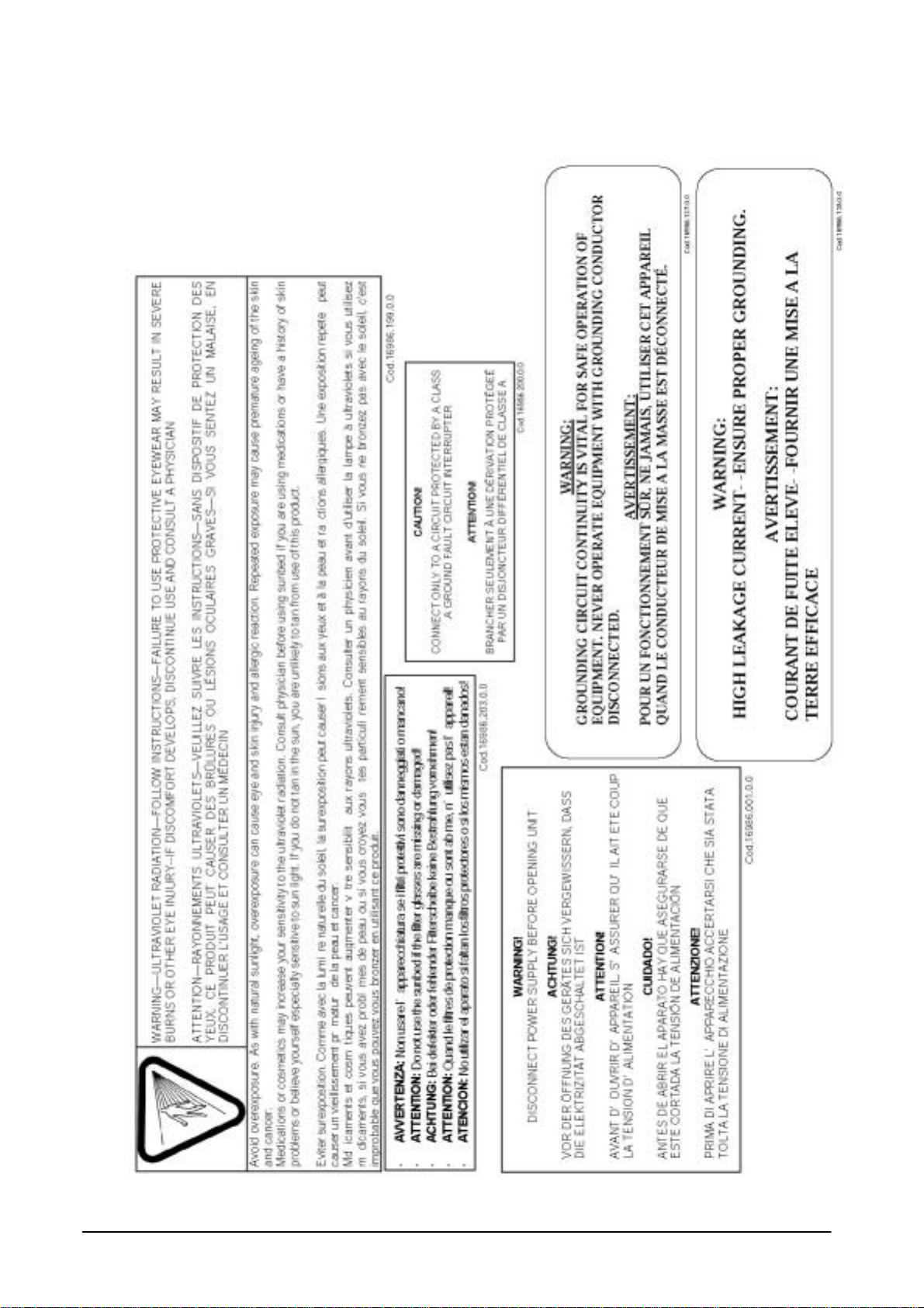
DANGER! Ultraviolet Radiation.
Follow instructions. Avoid overexposure. As with natural
sunlight, overexposure can cause eye and skin injury
and allergic reactions. Repeated exposure may cause
premature ageing of the skin and skin cancer.
WEAR PROTECTIVE EYEWEAR; FAILURE TO MAY
RESULT IN SEVERE BURNS OR LONG-TERM
INJURY TO THE EYES.
Medications or Cosmetics may increase your
sensitivity to the ultraviolet radiation. Consult physician
before using sunbed if you are using medications or
have a history of skin problems or believe yourself
especially sensitive to sunlight. If you do not tan in the
sun, you are unlikely to tan from the use of this product.
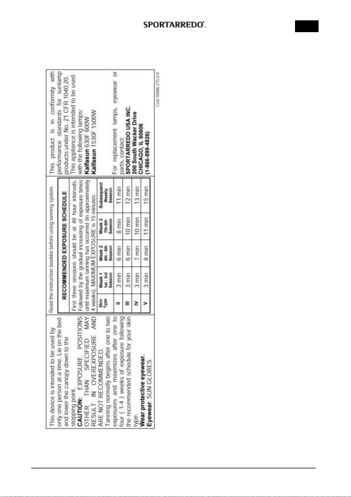
This device is intended to be used by only one person
at a time. Lie on the bed and lower the canopy down to
the stopping point.
CAUTION: EXPOSURE POSITIONS OTHER THAN
SPECIFIED MAY RESULT IN OVEREXPOSURE AND
ARE NOT RECOMMENDED.
Tanning normally begins after one to two exposures
and maximizes after one to four ( 1-4 ) weeks of
exposure following the recommended schedule for your
skin type.
Skin type II.
This is the individual that usually burns easily and
severely. Tans minimally or lightly and peels.
Skin type III.
Often referred to as “average” complexion burns
moderately and tans about average.
Skin type IV.
This individual burns minimally, tans easily and above
average.
Skin type V.
This individual’s system rarely burns, tans easily and
substantially.
Session times are calculated for a supply voltage of
208V.
This product is in conformity with performance
standards for sunlamp products under No.21 CFR
1040.20.
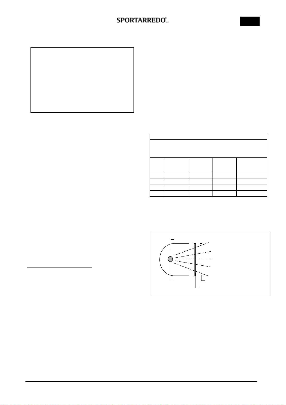
RECOMMENDED EXPOSURE SCHEDULE
First three sessions should be at 48 hour intervals. Followed by the
gradual increasing of exposure times until maximum tanning has
occurred (in approximately 4 weeks). MAXIMUM EXPOSURE is 15
minutes.
Skin
type Week 1
1st-3rd
Session
Week 2
4rd-6rd
Session
Week 3
7rd-9rd
Session
Subsequent
Weekly
Session
II 3 min. 6 min. 8 min. 11 min.
III 3 min. 6 min. 10 min. 12 min.
IV 3 min. 7 min. 10 min. 13 min.
V 3 min. 8 min. 11 min. 15 min.
This schedule is intended to be used with the following
lamps:
Kalfasun 630F
Kalfasun 1530F
Blue cobalt filter and clear Superlux TR-T filter
(together).
REFLE
C
T
O
R
LAMP
BLUE COBALT FILTER
CLEAR SUPERLUX TR
-
TFILTER
Cod. man.11084.112.0.0 (05/01/06) 5/38
USA
1.4 TRANSPORT AND HANDLING
The machine is carefully protected and loaded onto
pallets before shipping. The various parts of the
machine must never be transported or stored in
positions which differ from the positions in which they
are shipped. In this case, the warranty shall be null and
void.
The machine must be handled with care in order to
prevent the risk of damage to the packaged sections.
All handling operations should be carried out by
authorised and trained personnel. When the machine is
delivered, immediately check that the packaging
material is whole and that no damage has occurred
during transport.
Any damage to the machine must be notified to the
carrier not later than eight calendar days from the date
of delivery. If internal damage is suspected, it is
advisable to accept the machine reserving the right to
check accordingly.
THE CARRIER IS RESPONSIBLE FOR ANY
DAMAGE OCCURRING DURING TRANSPORT OF
THE MACHINE. SPORTARREDO WILL MAKE
EVERY EFFORT TO ASSIST THE CLIENT IN SUCH
CASES
ALL MAINTENANCE OF THE MACHINE MUST
BE PERFORMED BY SPECIALIZED
TECHNICIANS FROM SPORTARREDO OR BY
PERSONS AUTHORIZED BY SPORTARREDO
USA INC.
IMPORTANT !
ALWAYS DISCONNECT THE MACHINE
FROM THE POWER SUPPLY BY
PRESSING THE SWITCH BREAKER
BEFORE CARRYING OUT
MAINTENANCE
1.5 PREPARATION FOR INSTALLATION BY THE
CLIENT
Unless otherwise expressly specified in the contract, the
following must be provided by the client:
•Connections to the electrical circuit, including the
protective wire generally referred to as the "EARTH
CONNECTION", unit feeding cable, power plug
and circuit breaker.
•Canalization system for the emission of hot air.
•External air intake.
•All tools and equipment necessary for installation.
THE UNIT IS SUPPLIED FOR INPUT VOLTAGE AT
230V 3phase 60 Hz
AND IT IS SUPPLIED WITHOUT THE FEEDING
CABLE
To make a power cable connection or voltage-
change, make reference to the chapter
“INSTALLATION" paragraph “ VOLTAGE-CHANGE ”
and to the MASTERSUN 360 n° 1/10 electrical
diagram.
These operation must be done by technical
personnel.
THE BREAKER MUST BE INSTALLED IN THE
POWER SUPPLY BOARD OF THE ESTHETICAL
CENTRE AND IT MUST BE DONE BY THE CENTRE
ITSELF.
Mod. MASTERSUN 360:
3x80A-30mA to feed 230V - 3phase 60Hz
2x125A-30mA to feed 230V - 1phase 60Hz
The installation must be done by technical
personnel.
THE POWER SUPPLY CONNECTION (UNIT-
BOARD) MUST BE DONE BY THE CENTRE. THE
SKILLED TECHNICIAN MUST USE A CERTIFIED
CABLE WITH THE PROPER SECTION AND WITH
ADEQUATE MECHANICAL PROTECTION, IN
ACCORDANCE WITH THE RULES IN FORCE.
SEE CAHAPTER 2.1 TABLES FOR TECHNICAL
DATA “POWER SUPPLY CABLE SECTION”
PLEASE CONTACT THE CUSTOMER SERVICE AT
PHONE NUMBER
1-866-899-4826 FOR ANY FURTHER DOUBT
Before the evening closing, or the closing for a
prolonged period you should operate on the
breaker in order to disconnect the power supply.
TO HAVE A CORRECT USE OF THE
EQUIPMENT, THE ROOM TEMPERATURE MUST
NOT EXCEED THE 86°F DEGREES. IF ROOM
TEMPERATURE EXCEEDS THIS VALUE, WE
SUGGEST TO UTILIZE AN AIR-CONDITIONING
UNIT.
Cod. man.11084.112.0.0 (05/01/06) 6/38
USA
2 - SAFETY INFORMATION
2.1 GENERAL
The employer must ensure that the persons assigned to the
operation of the machine receive adequate training
concerning possible accident risks, the devices fitted for
the safety of the operator and the client, the risks
associated with the emission of UV light and the general
accident-prevention regulations specified by
international norms and local legislation.
Those responsible for operation, maintenance, cleaning
and control of the machine must adhere strictly to
the accident-prevention regulations applicable in the
country in which the machine is installed.
Before operating the machine, the operator must be
completely familiar with the position and the function
of all the controls and with the characteristics of the
machine. The operator must read this manual
carefully and completely.
The machine must be operated by fully-qualified
operators only.
Removal of the safety devices and protective barriers
is strictly forbidden.
No heavy weights must be placed on the moving parts
of the machine. The ventilation ducts and intake
grilles must not be obstructed by foreign bodies.
The machine must always be switched off and
disconnected from the power supply before
performing any routine or special maintenance
operations.
Unauthorised replacement of or repairs to any part or
section of the machine, or the use of accessories or
material that are not original or recommended by the
manufacturer, may represent a risk of injury, and
exonerate the manufacturer from all civil or penal
liability.
It is forbidden to stay near the appliance while it is
operating without eye protection.
"DANGEROUS ZONES": any zone internal to or in the
vicinity of the machine in which the presence of an
exposed person constitutes a risk for the safety and the
health of that person.
"EXPOSED PERSON": any person who is wholly or
partly in a dangerous zone.
"OPERATOR": person or persons assigned to the
installation, operation, adjustment, maintenance,
cleaning, repair and transport of the machine.
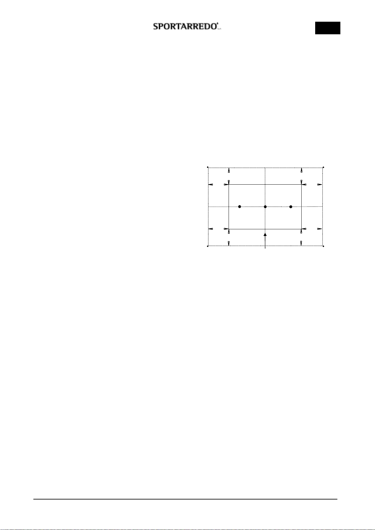
2.2 NOISE
The machine is designed and built in such a way as to
reduce operational noise as follows:
•Effective normalized sound power during operation,
see diagram below:
1= 74 dB (A) max 2= 73,5 dB (A) max 3= 73,6
dB (A) max 4= 73,3 dB (A) max
•Effective sound pressure with simulation of the actual
position of the person being treated:
A= 77,5 dB (A) max,
B= 78 dB (A) max,
C= 77,7 dB (A) max.
The figures shown above have been determined
according to ISO 3746.
2.3 REGULATIONS
Standard for Safety of Lunminaires, UL 1598, Issue:
2004/12/30 Ed: 2 Luminaires, CSA C22.2 No.250.0,
Issue: 2004/12/30 Ed: 2.
In the planning of this unit the following rules and
provisions of the European Community have been
taken in consideration:
ECC Directive N. 91/368 dated 20.06.91, N.93/44
dated 14.06.1993, N.93/68 dated 22.07.
ECC Directive N.73/23 dated 19.02.73 known as “low
voltage directive”.
ECC Directive N.89/336 dated 03.05.1989 known as
“Electronic compatibility directive”.
En 60335-2-27 II part Special standard for units for the
treatment of the skin with ultraviolet and infrared
rays for home use and similar use.
41
32
A
B
C
1m
1m
1m
1m
1m
1m
1m
1m
FRONT SIDE
Cod. man.11084.112.0.0 (05/01/06) 7/38
USA
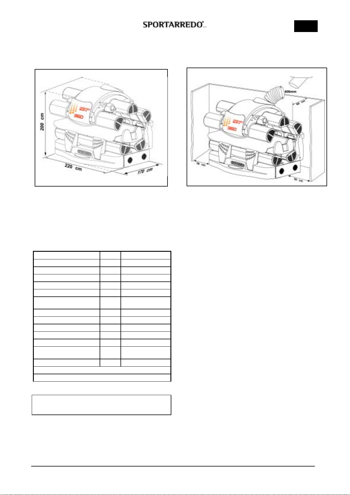
3 - TECHNICAL DATA
3.1 DIMENSIONS AND TECHNICAL DATA
MASTERSUN 360
MAXIMUM LENGTH 220 cm 86" in
MAXIMUM WIDTH 170 cm 67" in
MAXIMUM HEIGHT 200 cm 78" in
WEIGHT 880 Kg 1940 lb
MASTERSUN 360 U.M DATA
POWER SUPPLY V 230V 3ph 230V 1ph
NOMINAL POWER KW 25,3 24,1
NOMINAL CURRENT A 66 112
FREQUENCY Hz 60
WIRE SIZES AWG 4 1
NUMBER OF WIRE
REQUIRED 4 3
EXHAUST AIR FLOW m³/h 4x875
EXAUST FAN PRESSURE Pa 0÷200
HEAT PRODUCED Kcal/h 21800
HEAT EXPELLED Kcal/h 13100
FACE LAMPS TYPE No. 3xKALFASUN 1530F
CANOPY LAMPS TYPE No. 4xKALFASUN 1530F
11xKALFASUN 630F
BASE LAMPS TYPE No. 12xKALFASUN 630F
THERMIC PROTECTION 2x90°C
THERMIC PROTECTION 3x110°C
UV EMISSION
SEE RAY EMISSION CERTIFICATE
4 - INSTALLATION
4.1 PRE-INSTALLATION
In order to ensure correct operation of the machine, it
should be installed in an area which has been prepared
as shown in the figure.
The connection of the exhaust air pipe must have on
the first part (50-60 cm / 19"-23" inch from the edge of
the fan) the minimum curving. This device has to be
done to reduce the noise of the fan caused by the
resistance of the hair, to improve the cooling of the
lamps and to have a better air flow during the tanning
session.
4.2 CONNECTION
The area in which the machine is installed must be
adequately ventilated, fit the area with an air
intake from outside if necessary. To improve the
technical comfort we suggest to connect the tube to
expel the hot air to a fixed duct to expel the air
outward
•The metal structure of the machine is earthed by
means of insulated wires connected to the earth
terminal in the electrical junction box.
•The earth circuit must be in full compliance in
accordance with the rules in force.
•The earth connection must also be fitted to low-
voltage systems situated in wet or very damp areas
(if the voltage to earth is in excess of 25V for
alternating current or 50V for direct current).
•The earth wires connected to every part of the
various sections of the machine and the earth wires
from the various power circuits and user groups
must be connected to a single earthing circuit.
•Ensure that the materials used for the earth system
are suitably robust and provided with adequate
protection.
•The connection to the main earth terminal should be
as short as possible. The earth wires should not be
subjected to mechanical stress of any kind, and
must be protected against corrosion.
FIXED DUCT FOR HOT AIR
EXHAUST
Cod. man.11084.112.0.0 (05/01/06) 8/38
USA
4.3 ASSEMBLY INSTRUCTIONS
SEE ENCLOSED FIGURES
1 - Position the lateral Fon the floor at the minimum
distance at least 23" inc from the wall (see
paragraph 4.1 Pre-installation).
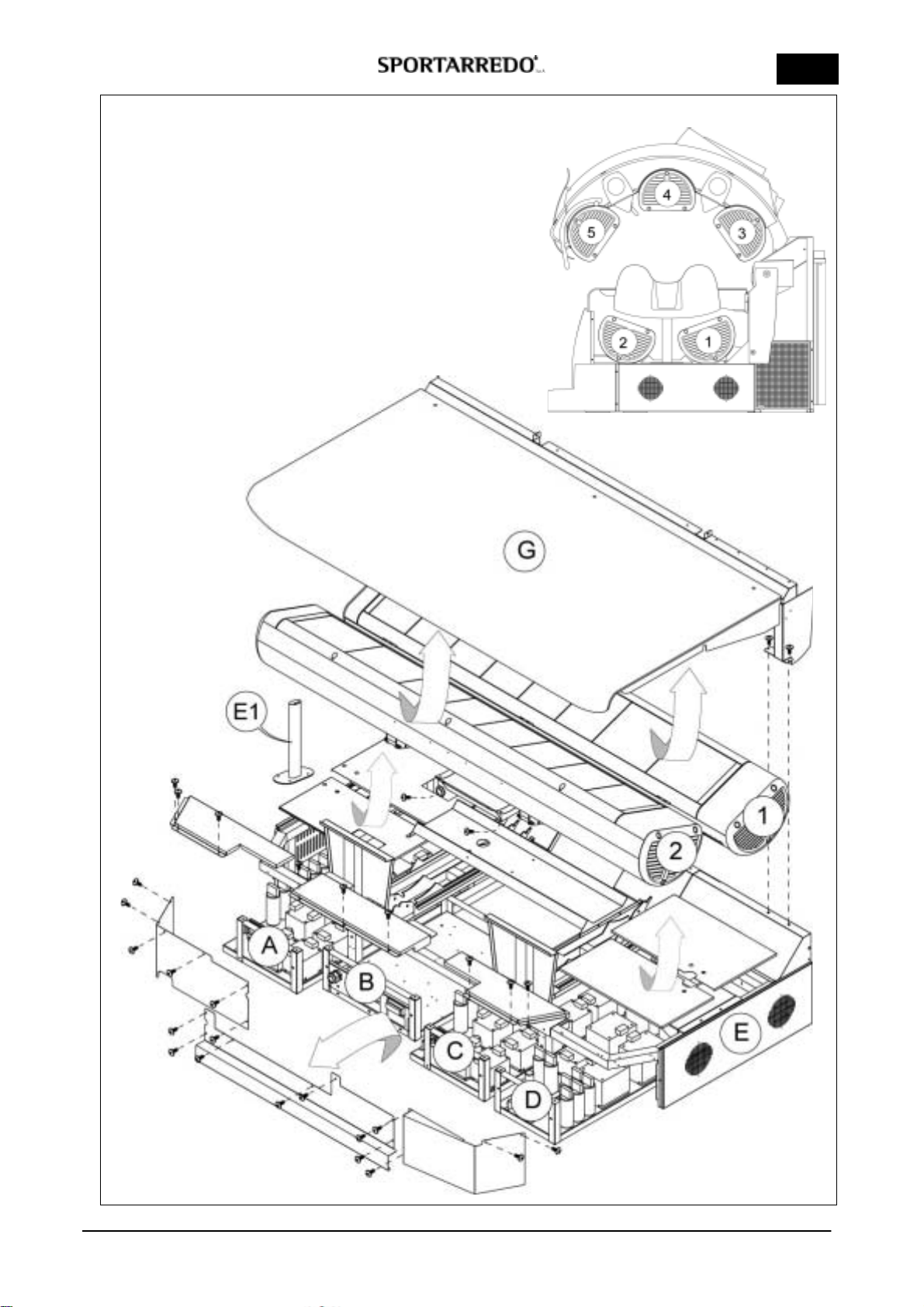
2 Figure 1
Open the packaging of basement E.
In case you need to install the unit into the
booth/room with a narrow door it is necessary to
dismantle the basement as shown. Otherwise
follow the assembling instructions at point 3.
Remove the screws 4,8x13 of the structure that
holds the body acrylic Gand put it aside.
Remove the screws 4,8x13 of the metallic covers
that protect frontally and upper the ABCD feeding
boxes.
Remove all the 4 ABCD feeding boxes.
Remove the screws 4,8x13 of the air conveyor
positioned under the column no. 2.
Remove column 2.
Remove column 1with the conveyor assembling.
Remove the screws 6x20 of the small column E1.
Remove the metallic covers positioned under
columns 1and 2.
3 Figure 2
Now the basement Eis completely dismantled, put
it to the lateral F. Assembly the basement Eto the
lateral Fwith 4 screws M12x60 and 16x36
washer.
Remove the panel in the lateral rear, fixed with
4,8x13 screws.
4 Figure 2-3
Position the ACD ballast boxes in front of the
basement. Before inserting the Dballast box,
make the connector CNT4 come out in the rear of
the lateral. The CNT4 cable connector is very long
and it must be withdraw into itself through the left
side of the lateral. The cable must be stopped by
the provided sheets and rests next to the white
signs. It mustn’t rest on the ballasts.
Insert the ballasts box D.
Insert the ballasts box A withdrawing the cables
CMB1-CNB2 on the left side of it
Before inserting the Cballasts box, make the
CNT3 connector come out from the right side of
lateral and the CNT5 connector from the left side.
The cables of the connectors must be withdraw
into themselves.
Insert the ballasts box C.
Place and fix the metallic covers on the ballasts
boxes with 4,8x13 screws.
Take the CNL connector from the lateral and get it
through the ballasts boxes side.
Make the connectors pass through the inner side
of the head arms insertion:
-CNT3- CNW3 to right DX
-CNT4-CNT5 to left SX
5 Figure 4
Assemble the column 1with the conveyor.
Connect the CNB1 connector from the A ballasts
box to the column 1.
Assemble the column 2and fix to it the conveyor
using 6 screws 4,8x13.
Connect the CNB2 connector from the A ballasts
box to the column 2.
Assemble the cooling conveyor of acrylic Hon the
frontal side of the lateral using 4,8x13 screws.
6 Figure and photo 5
Connect the 4 flexible grey pipes that convey the
air into the lateral white plastic clamps.
Connect the two black connectors CNW1-CNW2
of the fans into the lateral.
Fix into the provided sheets of the lateral these
connectors:
-CNT3- CNW3 to right DX
-CNT4-CNT5 to left SX
Assemble the rear panel of the lateral using
4,8x10 screws.
7 Figure 6
Assemble the structure using the screws 4,8x13
the structure that hold the body acrylic G.
Insert the brackets Zon lateral Ffixing them with
one security hexagonal-head 10x90 screw.
8 Figure 7
Insert the columns 3-4-5 in sequence. Assemble
them to the Z brackets with the security
hexagonal-head 10x90 screws and the self-
blocking bolt from inside to outside.
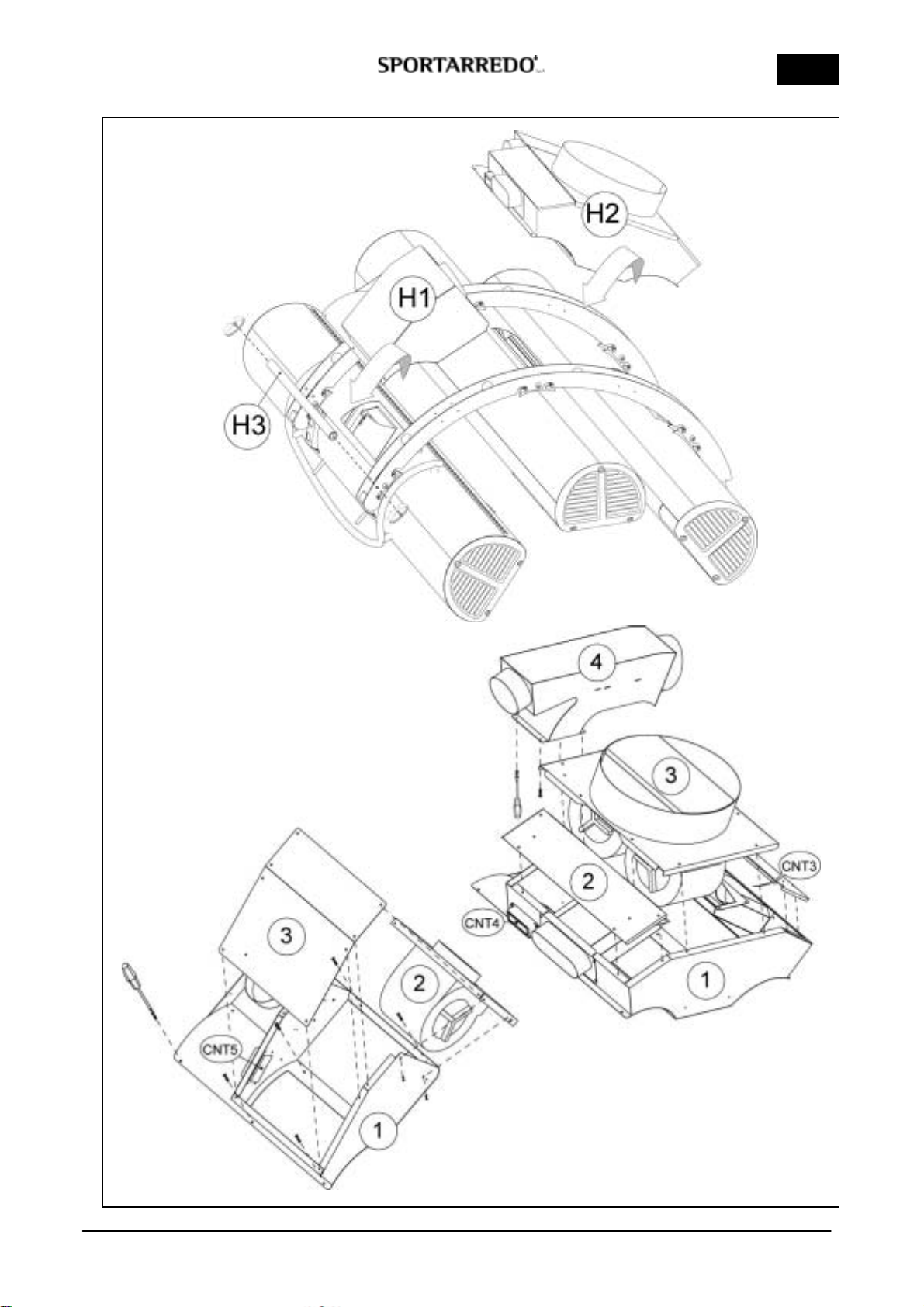
9 Figure 8
Assembling in sequence with 4,8x13 screws the
H2 covers with the two fans for hot air extraction.
Assembling the screws terminal- connector CNT3-
CNT4 and connect the white plugs of fans. The
part number 4 must be fixing to under with 4,8x13
screws.
Assemble in sequence with 4,8x13 screws the H1
cover fan. Assemble the screws terminal-
connector CNT5 and connect the white plug of the
fan. (Follow the sequence numbered).
Assemble the transversal tube H3 using
hexagonal-head 8x20 screws and 8x15 washer.

Cod. man.11084.112.0.0 (05/01/06) 9/38
USA
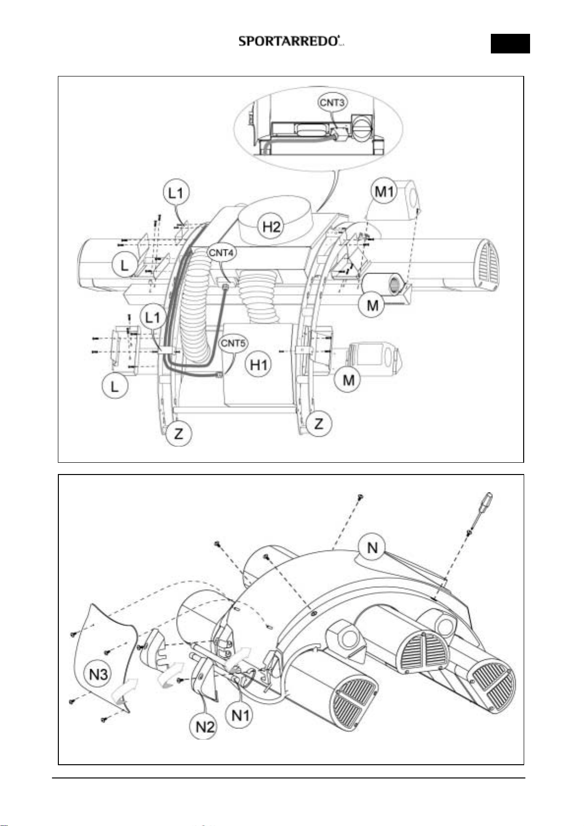
10 Figure 9
Assemble the Lsheets for the support of the
cooling body conveyors on the brackets Zusing
5x15 screws and 5x15 washer. The air body
conveyor with handle has to be inserted between
columns 4 and 5 .
Assemble the Mair body conveyors without the
fan plastic covers with hexagonal-head 6x20
screws.
Fit the canopy connectors CNT3-CNT4-CNT5
inserting them under the L1 sheets (see figure 9).
Insert the plastic covers M1 on the fans.
Connect the grey pipes for the air convey.
Make the connectors pass through CNT3-CNT4-
CNT5 inside the brackets Z(right DX-left SX), the
cables must be fixed to the provided rests next to
the white signs. Insert the cables as shown in
figure under the L1 sheet and connect they on
conveyor H1-H2 according indications.
Assemble the M1 cover plastic on fans.
Connect the flexible grey pipes that convey the air.
Connect the black connectors CNW3-CNW7-
CNW8-CNW9 positioned at the lateral of the
convey H1.
11 Figure 10
Assemble the cover Nwith 2 screws 6x20 in the
rear and in front with 2 screws 6x25 with teflon
washer.
Insert the two yellow neon lamps N1.
Assemble the two caps N2 with 6x20 screws and
teflon washer.
Insert the panel N3 silkscreen printing: Mastersun
360 with 6x20 screws and teflon washer.
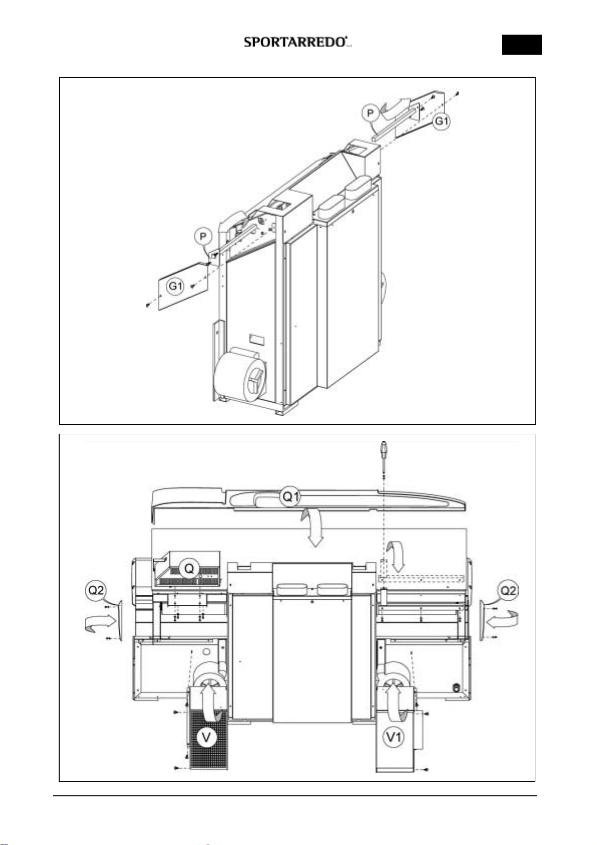
12 Figure 11
Remove the 5x15 screw with washer and remove
the tubes Pthat block the mechanical rising of
unit. Assemble the G1 sheets (right-left), with
4,8x13 screws.
13 Figure 12
Assemble the Qbox of control board using the 4
hexagonal-head 6x20 screws with 6 washers.
Connect the CNC and CN2 connectors of fan V
below.
Assemble the grating cover fan Vwith 4,8x13
screws connecting the earth wire.
Assemble the cover fan V1 with 4,8x13 screws
connecting the earth wire.
Assemble the antenna on Qcontrol board box.
Insert and fix the lateral plastic cover Q1 using
6x20 screw with teflon washers.
Assemble the lateral cover plastic Q2 with 4,2x22
black screws.
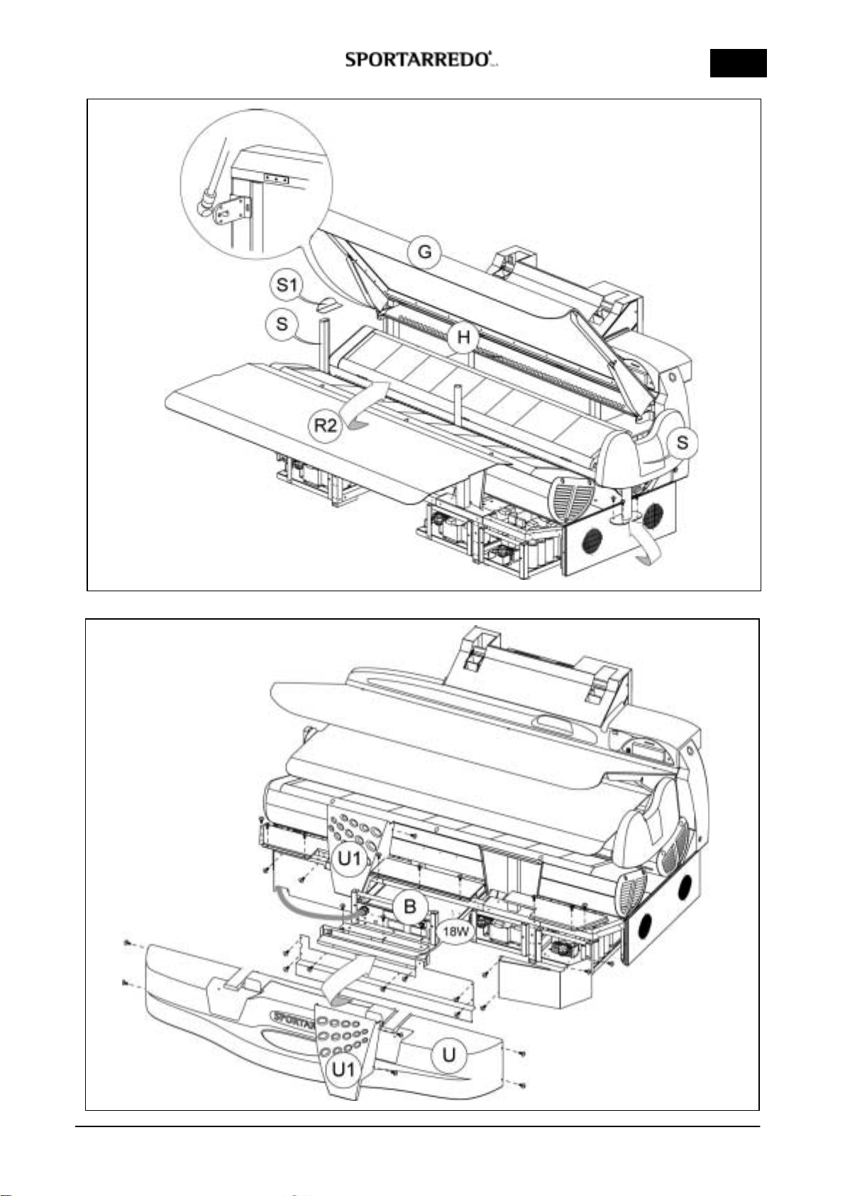
14 Figure 13
Raise the R1 body acrylic. Fix the pistons tighten
up and block with release (with small pins) in the
lower part.
Assemble the column Sand use 4 screws 6x20
with the dent facing toward inwards.
Position the loudspeakers column S and before
assembling using 4 screws 6x20 connect the
white connector CN1.
Insert on the columns Sthe sheets S1 for acrylic
supports.
Insert between the columns 1and 2the acrylic
tube.
Insert the R2 acrylic into the Hconveyor and place
it on the small sheet S1 and on the acrylic tube.
Rise the body acrylic G.
15 Figure 14
Insert partially the Bfeeding box in to the
basement. Insert the feeding cable (see also
figure 16 with change voltage) and connect it to
the power supply terminal board. Finally insert
completely the Bfeeding box in to the basement
and connect the connectors: CNRT-CNRB-CNRV-
CNL-CNW4.
Assembly the neon-holder with the 18W lamp in
correspondence of the feeding box B using 2
screws 4,8x13 and connect the connector CNW5.
Assembly the metallic cover sheets on all ballasts
boxes and afterwards those in front using 4,8x13
Screws.
16 Figure14
Assemble the Ufrontal plastic basement with
4,2x22 black screws. Lift the body acrylic and
assemble the orange covers plastic U1 on the
columns of acrylic support using 4,2x22 black
screws.
Rise the body acrylic.
Place the gel carpet on the Ubasement.
Place the gel cushion on body acrylic.
Switching on the equipment the lamps don't switch
on at the same moment but in sequence: in order
to avoid excessive picks if current absorption.
Check that the all fans emit air, just putting the
hand in front.
Remove the numbers labels 1-2-3-4-5 on
columns.
WARNING!
In the control box there is a safety timer set this
timer at a value 10% longer than the maximum
session time.
e.g.: session time 15 min set the safety timer to
16,5 min.
Cod. man.11084.112.0.0 (05/01/06) 10/38
USA
FIGURE 1 COLUMNS NUMBERS

Cod. man.11084.112.0.0 (05/01/06) 11/38
USA
FIGURE 3
FIGURE 2

Cod. man.11084.112.0.0 (05/01/06) 12/38
USA
FIGURE 5
FIGURE 4

Cod. man.11084.112.0.0 (05/01/06) 13/38
USA
FIGURE 6
FIGURE 7
Cod. man.11084.112.0.0 (05/01/06) 14/38
USA
FIGURE 8
Cod. man.11084.112.0.0 (05/01/06) 15/38
USA
FIGURE 9
FIGURE 10
Cod. man.11084.112.0.0 (05/01/06) 16/38
USA
FIGURE 11
FIGURE 12
Cod. man.11084.112.0.0 (05/01/06) 17/38
USA
FIGURE 13
FIGURE 14
Cod. man.11084.112.0.0 (05/01/06) 18/38
USA
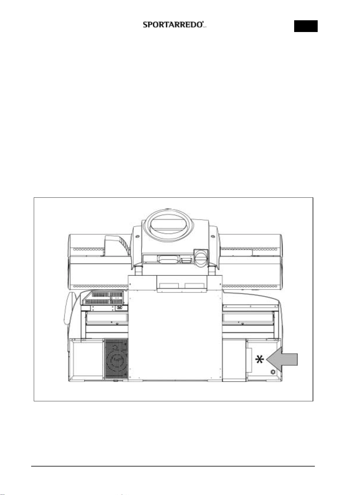
AIR-CONDITIONING CONNECTION
The unit can be connected to an external air-
conditioning system (separate system, not equipped
with the unit or directly to the tanning centre air-
conditioning system) to increase the user’s comfort.
The connection to the air-conditioning system permits to
cool the surface of the acrylic that support the client
during the session, increasing the comfort of the unit.
The unit can also function without the connection to an
auxiliary air-conditioning system, but for a better
comfort of the user, Sportarredo always suggests to
connect the unit to an auxiliary cooling system.
The connection must be done as follows:
Use a flexible pipe diameter 254 cm, max. 2m long
avoiding narrowing or a sharp turn.
Connect the pipe to the air socket placed on the cover
of the cooling base fan behind the base of the unit (see
figure *).
Connect the other end of the pipe to the external air
duct from the air-conditioning system (centralised or
external air-conditioning system).
The air-conditioning system must be able to supply the
following performance:
Air Output: min. 900-1000 m3/h
Cooling Power: 9.000-12.000 BTU
Air outlet temperature: at discretion of the user,
however no higher than 25 °C
FIGURE 15
Cod. man.11084.112.0.0 (05/01/06) 19/38
USA
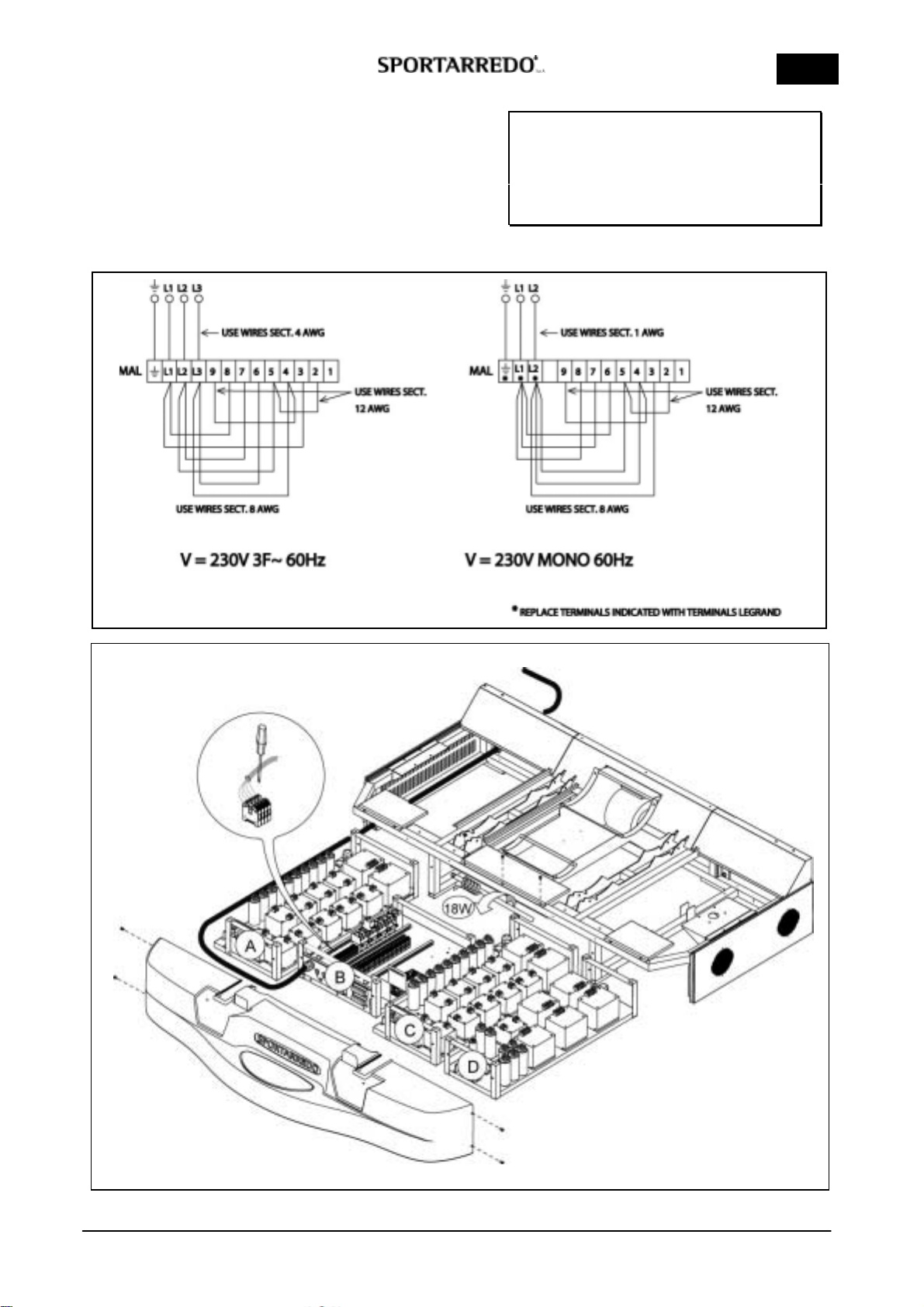
4.4 VOLTAGE CHANGE
To enter the terminal board for power supply, placed
inside the basement (control box B).
Before taking the control box Boff, remove the bracket
with the lamp 18w.
Make reference to Picture 1 and Figure 16.
IMPORTANT !
ALWAYS DISCONNECT THE MACHINE
FROM THE POWER SUPPLY BY
PRESSING THE SWITCH BREAKER
BEFORE CARRYING OUT
MAINTENANCE
FIGURE 16
Picture 1


