SSI Smart Cities Solaria User manual

Solaria
User Guide
ersion 1.0
2
Release Notes
Dates
Release
Description
2023 03 14
Version 1.0
Initial Release

3
Content
1. Regulatory Regions .............................................................................................................7
1.1. FCC Statement and IC Statement ........................................................................................................... 7
1.2. European CE .......................................................................................................................................... 8
2. Introduction........................................................................................................................9
2.1. SOLARIA Intelligent Integrated Reader with 1 External Port .................................................................. 9
2.2. Software development kits.................................................................................................................... 9
3. Reader Basics....................................................................................................................10
3.1. Basic Hardware.....................................................................................................................................10
3.2. Connectors pin out details....................................................................................................................12
3.3.Set up Hardware...................................................................................................................................14
3.4. Mounting of the SOLARIA Reader.........................................................................................................15
3.5. How to Connect to and Configure SOLARIA ........................................................................................16
3.6. Connecting to the SOLARIA reader using Browser ................................................................................17
3.7. Connecting to the SOLARIA reader via SSH ...........................................................................................19
3.8. Embedded Linux Applications Development.........................................................................................21
3.9. GPIO Port and Accessories for Connection............................................................................................22
4. GPIO Ports Connection Guide ............................................................................................23
4.1. General Purpose Input (GPI) .................................................................................................................23
4.2. General Purpose Output (GPO).............................................................................................................28
5. Web Browser Interface Details ..........................................................................................31
5.1. Home Page ...........................................................................................................................................31
5.2. Status ...................................................................................................................................................32
5.3. Users Management...............................................................................................................................34
5.4. System..................................................................................................................................................37
5.4.1. Reader ID..............................................................................................................................................38

4
5.4.2. The Capture Point Name can be modified in this page..........................................................................38
5.4.3. Access Mode.........................................................................................................................................39
5.4.3.1.
5.4.3.2.
5.4.4.
5.4.4.1.
5.4.5.
5.4.6.
5.4.7.
5.4.7.1.
5.4.7.2.
5.4.8.
Set Access Mode...............................................................................................................................40
Custom Embedded RFID application.................................................................................................40
Frequency Configuration ......................................................................................................................41
Set Regulatory Region .................................................................................... .................................41
Operation Profile..............................................................................................................................42
Memory Information........................................................................................................................44
Configuration Backup/Restore..............................................................................................................44
5.4.8.1. Add Power Up Notification...............................................................................................................46
5.4.9. Heartbeat .............................................................................................................................................
Configuration Backup .......................................................................................................................44
Configuration Restore ......................................................................................................................45
Power Up Notification ..........................................................................................................................46
46
5.4.9.1. Add Heat Beat ..................................................................................................................................46
5.4.10. Log File Configuration ...........................................................................................................................47
5.4.11. Download Log file.................................................................................................................................48
5.4.12. Company Label .....................................................................................................................................48
5.4.13. Advanced Settings ................................................................................................................................49
5.4.14. Scheduled Restart.................................................................................................................................49
5.5. Restart System......................................................................................................................................50
5.6. Network Management..........................................................................................................................51
5.6.1. Ethernet Configuration .........................................................................................................................52
5.7. Time and Timer Setting.........................................................................................................................53
5.7.1. Date/Time ............................................................................................................................................53
5.7.2. Time Zone.............................................................................................................................................54
5.7.3. NTP Setup.............................................................................................................................................54
5.8. Tag & Tag Filter.....................................................................................................................................55

5
5.8.1. Tag Group.............................................................................................................................................55
5.8.2. Tag Database ........................................................................................................................................59
5.8.3. Tag Filter...............................................................................................................................................66
5.9. I/O Management ..................................................................................................................................69
5.9.1. I/O Port Testing ....................................................................................................................................69
5.10. Event Management ..............................................................................................................................70
5.10.1. Event Management ..............................................................................................................................71
5.10.1.1. Add Event.........................................................................................................................................71
5.10.1.2. Modify Event ....................................................................................................................................73
5.10.1.3. Enable/Disable Event .......................................................................................................................74
5.10.1.4. Delete Event.....................................................................................................................................75
5.10.1.5. List Event..........................................................................................................................................75
5.10.2. Trigger ..................................................................................................................................................76
5.10.2.1. Add Trigger.......................................................................................................................................76
5.10.2.2. Modify Trigger..................................................................................................................................79
5.10.2.3. Delete Trigger...................................................................................................................................80
5.10.2.4. List Trigger........................................................................................................................................81
5.10.3. Resultant Action ...................................................................................................................................81
5.10.3.1. Add Resultant Action........................................................................................................................82
5.10.3.2. Modify Resultant Action...................................................................................................................85
5.10.3.3. Delete Resultant Action....................................................................................................................86
5.10.3.4. List Resultant Action.........................................................................................................................87
5.10.4. Tag Inventory........................................................................................................................................87
5.10.4.1. Display Tag Group/Database Record ................................................................................................88
5.11. Version Management ...........................................................................................................................89
5.11.1. Version Control.....................................................................................................................................89
5.12. Firmware Upgrade................................................................................................................................90
5.12.1. Upgrading Web Application..................................................................................................................90

6
5.12.2. Upgrading JNI Library............................................................................................................................92
5.12.3. Upgrading SSI API library ......................................................................................................................93
6. Read Tag using Web Interface and Event Engine ................................................................95
6.1. Read Tag using Default Profile and Default Event .................................................................................95
6.2. Example 1: Read Tag using Custom Profile and Custom Event ..............................................................97
6.3. Example 2: Example Event using Database Tag Group and Database Display .....................................106
Read Tag using Custom Embedded RFID ................................................................................. 115
Appendix: ............................................................................................... ..............................116

7
1. Regulatory Regions
1.1. FCC Statement and IC Statement
FCC STATEMENT
1. This device complies with Part 15 of the FCC Rules. Operation is subject to the following two
conditions:
(1) This device may not cause harmful interference.
(2) This device must accept any interference received, including interference that may cause undesired
operation.
2. Changes or modifications not expressly approved by the party responsible for compliance could void the
user's authority to operate the equipment.
NOTE: This equipment has been tested and found to comply with the limits for a Class B digital device,
pursuant to part 15 of the FCC Rules. These limits are designed to provide reasonable protection against
harmful interference in a residential installation.
This equipment generates uses and can radiate radio frequency energy and, if not installed and used in
accordance with the instructions, may cause harmful interference to radio communications. However, there
is no guarantee that interference will not occur in a particular installation. If this equipment does cause
harmful interference to radio or television reception, which can be determined by turning the equipment off
and on, the user is encouraged to try to correct the interference by one or more of the following measures:
- Reorient or relocate the receiving antenna.
- Increase the separation between the equipment and receiver.
-Connect the equipment into an outlet on a circuit different from that to which the receiver is connected.
-Consult the dealer or an experienced radio/TV technician for help.
This equipment complies with FCC radiation exposure limits set forth for an uncontrolled environment.
This equipment should be installed and operated with minimum distance 20cm between the radiator &
your body

8
1.2.
IC STATEMENT
This device complies with Industry Canada licence-exempt RSS standard(s). Operation is subject to the
following two conditions: (1) This device may not cause harmful interference, and (2) this device must
accept any interference received, including interference that may cause undesired operation of the
device. In additional, this device complies with ICES-003 of the Industry Canada (IC) Rules.
Any Changes or modifications not expressly approved by the party responsible for compliance could
void the user's authority to operate the equipment.
Note: This equipment has been tested and found to comply with the limits for a Class B digital device,
pursuant to Industry Canada licence-exempt RSS standard(s). These limits are designed to provide
reasonable protection against harmful interference in a residential installation. This equipment generates
uses and can radiate radio frequency energy and, if not installed and used in accordance with the
instructions, may cause harmful interference to radio communications. However, there is no guarantee
that interference will not occur in a particular installation. If this equipment does cause harmful
interference to radio or television reception, which can be determined by turning the equipment off and
on, the user is encouraged to try to correct the interference by one or more of the following measures:
-Reorient or relocate the receiving antenna.
-Increase the separation between the equipment and receiver.
-Connect the equipment into an outlet on a circuit different from that to which the receiver is connected.
-Consult the dealer or an experienced radio/TV technician for help.
This equipment complies with RSS-102 radiation exposure limits set forth for an uncontrolled
environment. This equipment should be installed and operated with minimum distance 20cm between
the radiator & your body.
Note: French version please see end page.
European CE
Frequency range (CE) for RFID operation comprises:
1.
865-868 MHz band with 4 frequency channels

9
2. Introduction
2.1. SOLARIA Intelligent Integrated Reader with 1 External Port
The SOLARIA Integrated reader is an intelligent reader designed to work standalone in an autonomous
manner. An intelligent Event Engine is embedded with configurable complex logic sequence, triggers and
resultant actions that are automatically activated on power up. The settings can be saved and further
deployed to as many readers, as many sites as you want, thus providing easy scalability for system
integrators. SOLARIA integrated reader has 1 embedded antenna, plus 1 RF port that connects to an
external antenna.
Figure 1. The SOLARIA reader has the following connectivity: Ethernet; GPIO; N-Type Antenna Port.
2.2. Software development kits
Software development kits are available in SSI website:
1) .NET API (HTTP)
2) .JAVA API
3) Custom Embedded RFID: sample codes in /opt
10
3. Reader Basics
3.1. Basic Hardware
The SOLARIA is an Integrated RFID reader.
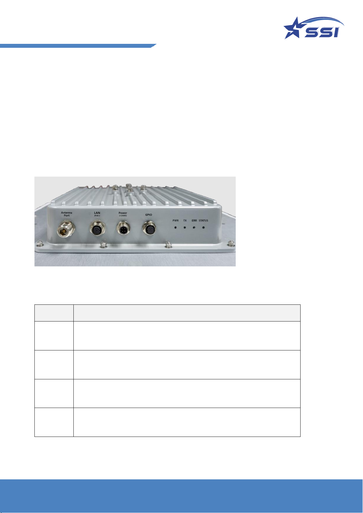
Below is a side view of the SOLARIA Integrated Reader.
The LED indicators show the operating status of the reader.
Figure 2. SOLARIA connectors and LED indicators
LED
Operational description
Power
[PWR]
GREEN indicates power is applied to the reader
Transmit
[TX]
GREEN when transmitting
Error
[ERR]
RED indicates one or more radio error have occurred.
STATUS
Ethernet Status. AMBER indicates the Link while the GREEN indicates the activity
of the ethernet connection
11
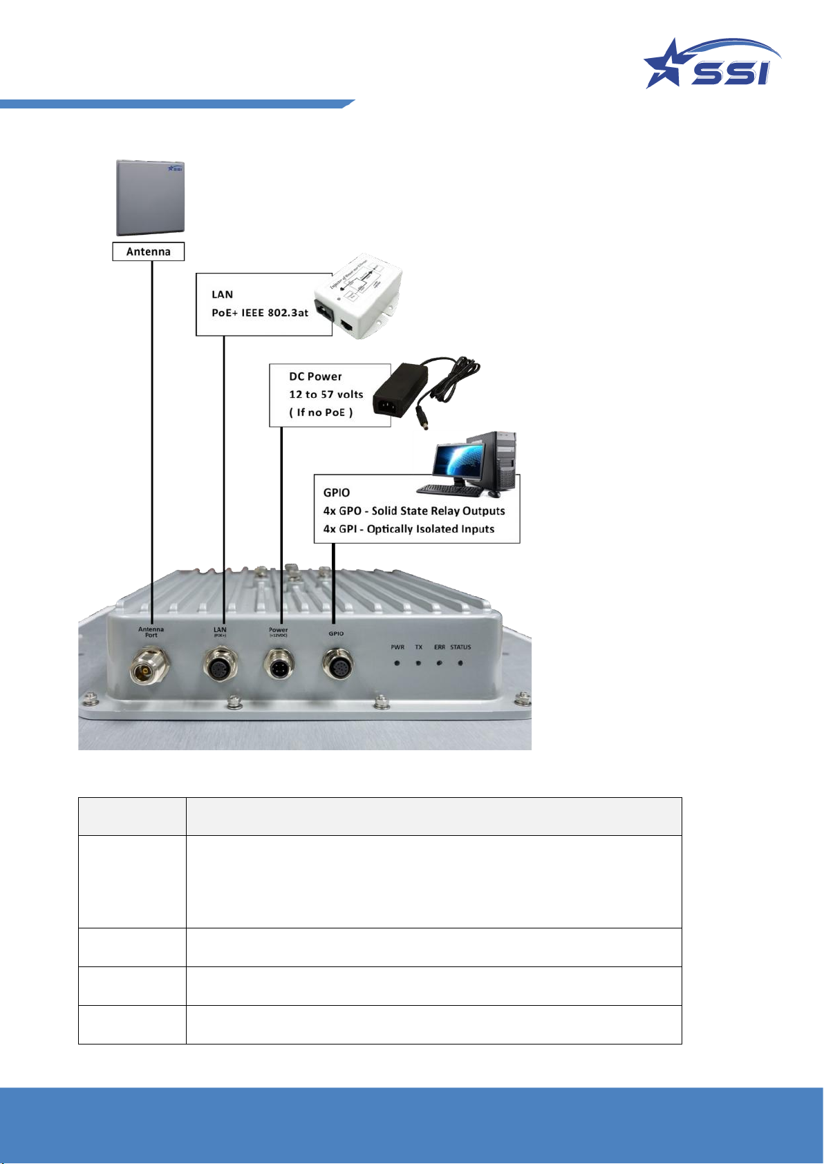
Figure 3. SOLARIA connection diagram
Interface
Description
LAN
PoE+ (IEEE 802.3at Compliant (Type 2);
Ethernet interface: IEEE 802.3 10BASE-T/100BASE-TX IEEE 802.3 compliant
Ethernet transceiver through an RJ-45 connector that has PoE+ magnetics.
Power
DC power supply - 12V, 5A (60 Watts) Or PoE+ (IEEE 802.3at Compliant, 30W)
GPIO
4 pairs Opto-isolated inputs and outputs
Antenna Port
External Antenna port with N-type connector

12
3.2. Connectors pin out details.
The following diagram provides specific details regarding each connector type:
Figure 4. Different types of M12 connectors
Ethernet - LAN(PoE+):
Pin
Mode A
Mode B
Description
1
Rx+, DC+
Rx+
LAN Rx+, DC+ for Mode A PoE Spec
2
Rx-, DC+
Rx-
LAN Rx-, DC+ for Mode A PoE Spec
3
Tx+, DC-
Tx+
LAN Tx+, DC- for Mode A PoE Spec
4
Unused
DC+
DC+ for Mode B PoE Spec
5
Unused
DC+
DC+ for Mode B PoE Spec
6
Tx-, DC-
Tx-
LAN Tx-, DC- for Mode A PoE Spec
7
Unused
DC-
DC- for Mode B PoE Spec
8
Unused
DC-
DC- for Mode B PoE Spec
13
Power - DC:
Pin
Signal
Description
Color
1
+V
Voltage (12-57v)
Brown
2
GND
Ground
White
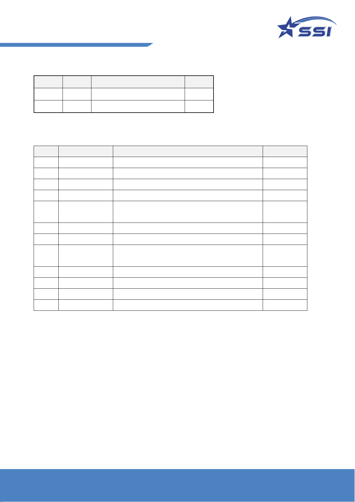
GPIO
PIN
Signal
Description
Color
1
GPO3
Open Collector General Purpose Output #3
Brown
2
GPI1_3_Return
Optically isolated Input #1 and #3 common return
Blue
3
GPI2
Optically isolated input #2
White
4
GPI3
Optically isolated input#3
Green
5
GPO2_3_Return
Open Collector General purpose output #2 and #3
common return
Pink
6
GPI1
Optically isolated input #1
Yellow
7
GPO2
Open Collector General Purpose Output #2
Black
8
GPO0_1_Return
Open Collector General purpose output #0 and #1
common return
Gray
9
GPI0
Optically isolated input #0
Red
10
GPO1
Open Collector General Purpose Output #1
Purple
11
GPI0_2_Return
Optically isolated Input #0 and #2 common return
Red/Gray
12
GPO0
Open Collector General Purpose Output #0
Red/Blue

14
3.3. Hardware set up
a) DC Power
The Solaria reader can be powered up by (1) AC/DC power or (2) PoE+ (802.3at PSE,30W) injector
1) Option 1: By AC Adaptor Unit [Optional Accessory]
SOLARIA connect the AC adapter via the M12 Power cable and DC converter (optional).
Please screw tight the lock on the M12 connector to ensure reliable power connection.
By that way, the connector pair would not loosen up over time.
With the power connected, the Power LED indicator should light up immediately.
2) Option 2: PoE+ (802.3at PSE,30W)
SOLARIA also supports the use of Power over Ethernet (PoE+) to power up.
NOTE: It must be PoE Plus (comply with 802.3at) rated at 30W PSE to make sure enough
power to SOLARIA.
Make sure you use PoE+ port or a PoE+ Switch to ensure SOLARIA receive enough power to
operate. Alternatively, use a PoE+ injector for the power source.
b) RFID External Antenna Connection
With the external antenna port, SOLARIA can connect with one external RFID antenna with wrench
(8mm torque with 100 N-cm).
Note: External antenna info as below:
1) Model: Kuma Gain:10dBi Manufacturer: STAR Systems International Ltd.
2) Model: Avalon Gain:13 dBi Manufacturer: STAR Systems International Ltd.
3) Model: Cheetah Gain:12dBi Manufacturer: STAR Systems International Ltd.
4) Model: Avior Gain:15dBi Manufacturer: STAR Systems International Ltd.

15
3.4. Mounting of the SOLARIA Reader
Installation method on metal poles:
Using the mounting bracket provided, the reader can be mounted onto a pole with a diameter of 40-60
mm.
1. Put on the mounting bracket in the orientation needed and put on the bolts. Tighten the bolts using
a wrench.
IMPORTANT: ONLY USE THE BOLTS PROVIDED
2. Assemble the mounting bracket according to the figure shown.
3. Installing the Earth Cable on metal poles:
For proper and safe installation, you must properly ground the reader using a piece of suitable length earth
wire connected on the reader side which is also attached the other end to a properly earthed location.
THIS IS REQUIRED TO FULFILL SAFETY AND REGULATORY REQUIREMENTS!
16
3.5. How to Connect to and Configure SOLARIA
User can connect to SOLARIA reader via Ethernet in the following ways:
1) Use the browser interface and the built-in event engine to configure the reader to run automatically
based on certain logic sequence.
2) Write embedded program in the Linux OS inside directly to configure and control the reader.
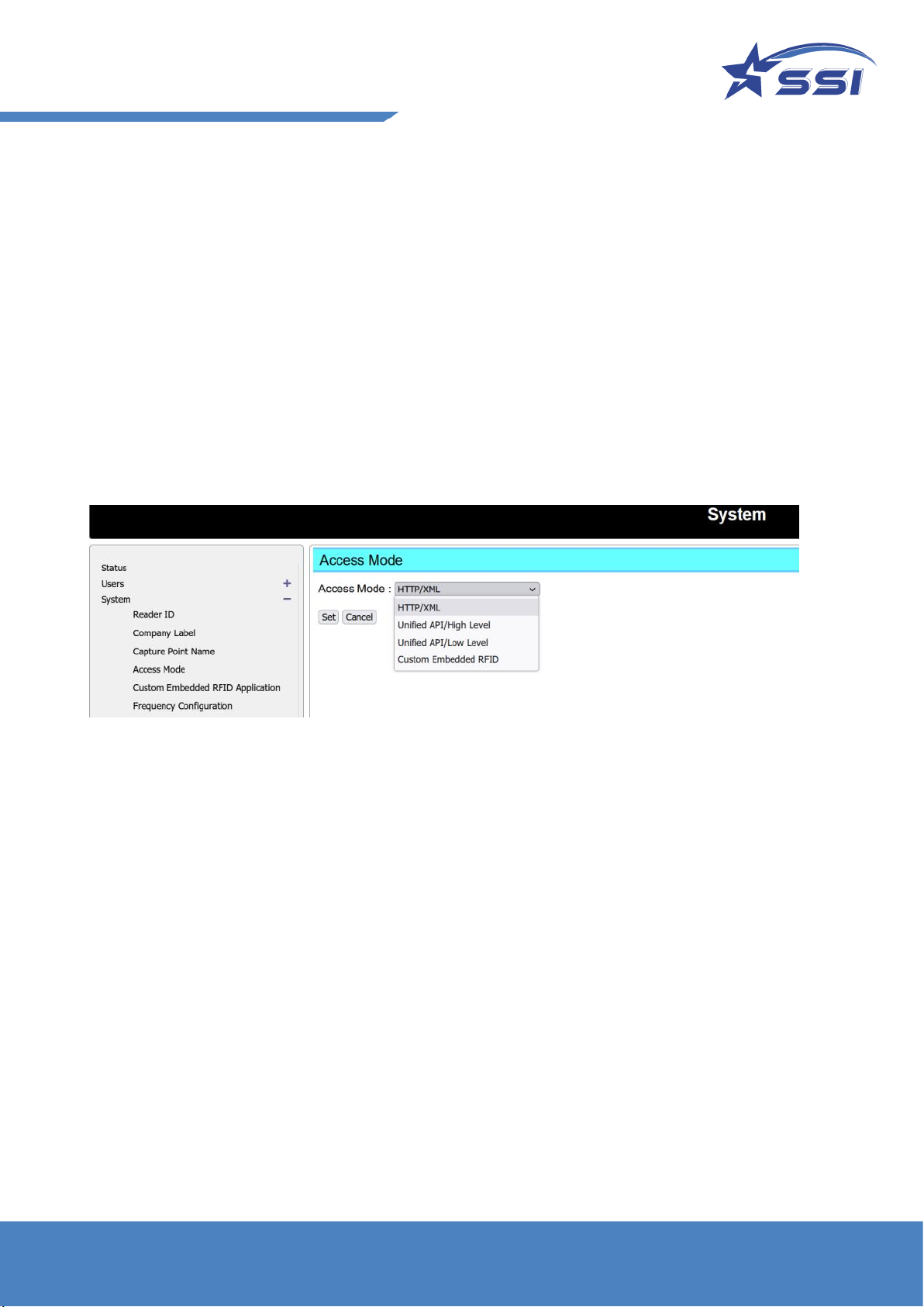
To switch the connection interface, go to the browser interface, System/Access Mode page, and then
choose the Access Mode, as shown below:

17
3.6. Connecting to the SOLARIA reader using Browser
SOLARA Reader is set to connect to Ethernet in DHCP mode.
Connect Ethernet cable from your PC to the reader directly, or via an Ethernet switch while the reader is
powered by DC adapter. Make sure the host is configured to work as a DHCP server. If the reader is
powered up by PoE+ Switch or PoE+ injector, make sure the host is set in the same subnet and there should
be a DHCP server in the subnet.
The reader may take up to 1 minute to boot up after connected the power.
Use a 3rd party IP scanning tool like Advance IP Scanner. Look for the Solaria Reader and its corresponding
IP:
Open the browser and type in the IP found in the previous step. It is 192.168.10.84 in this example.

18
A User Login page will be shown
Key in User Name: stars, Password: systems then click Login
The Status page is showed up after login.
Default Access Mode should be HTTP/XML. Change the Access Mode if reader is not in HTTP/XML mode
•In order to read and show RFID tags in Web page, please change the Access Mode to
“HTTP/XML“ as shown below in System page.
•Please click “Set” to confirm the change.

20
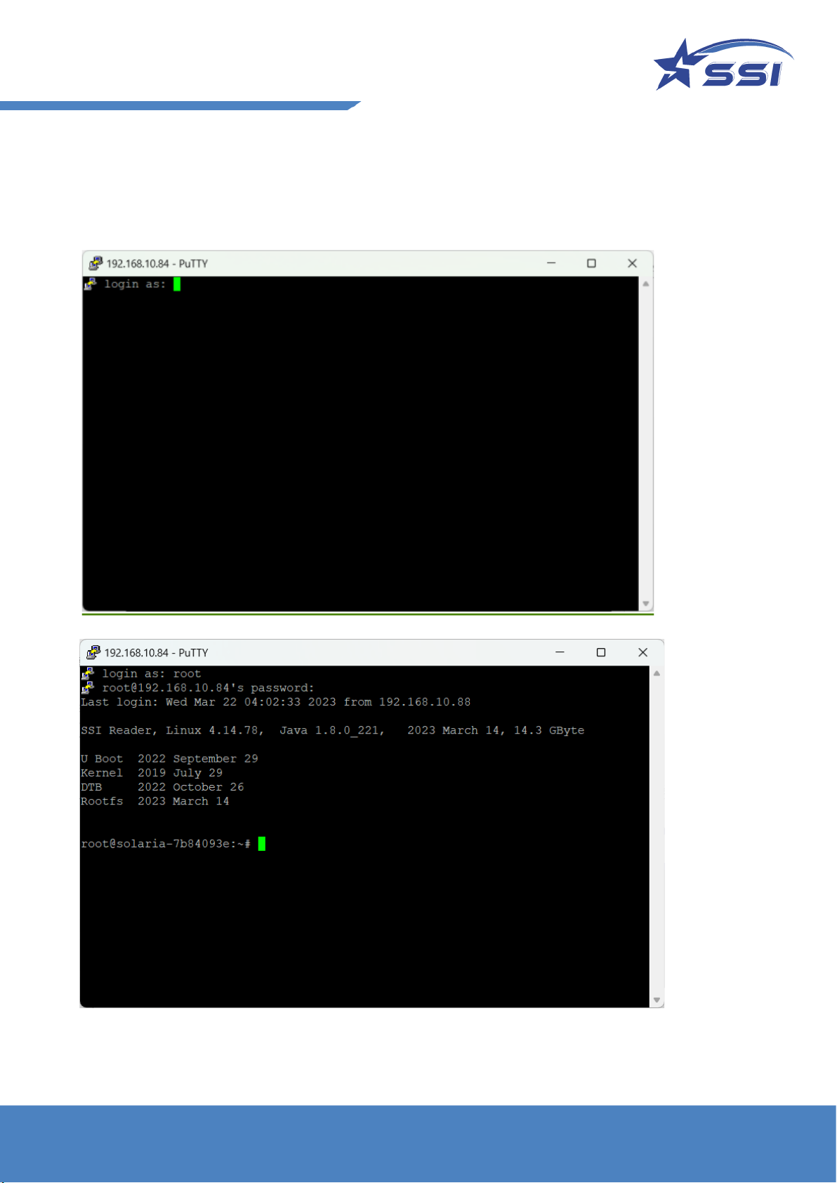
Next, you should type in
Login name : root
Password : hRd29sLr23
Table of contents