Star Lights SMART LIGHT 1000 User manual
- 1 -
REV-7.23.2012, CSA
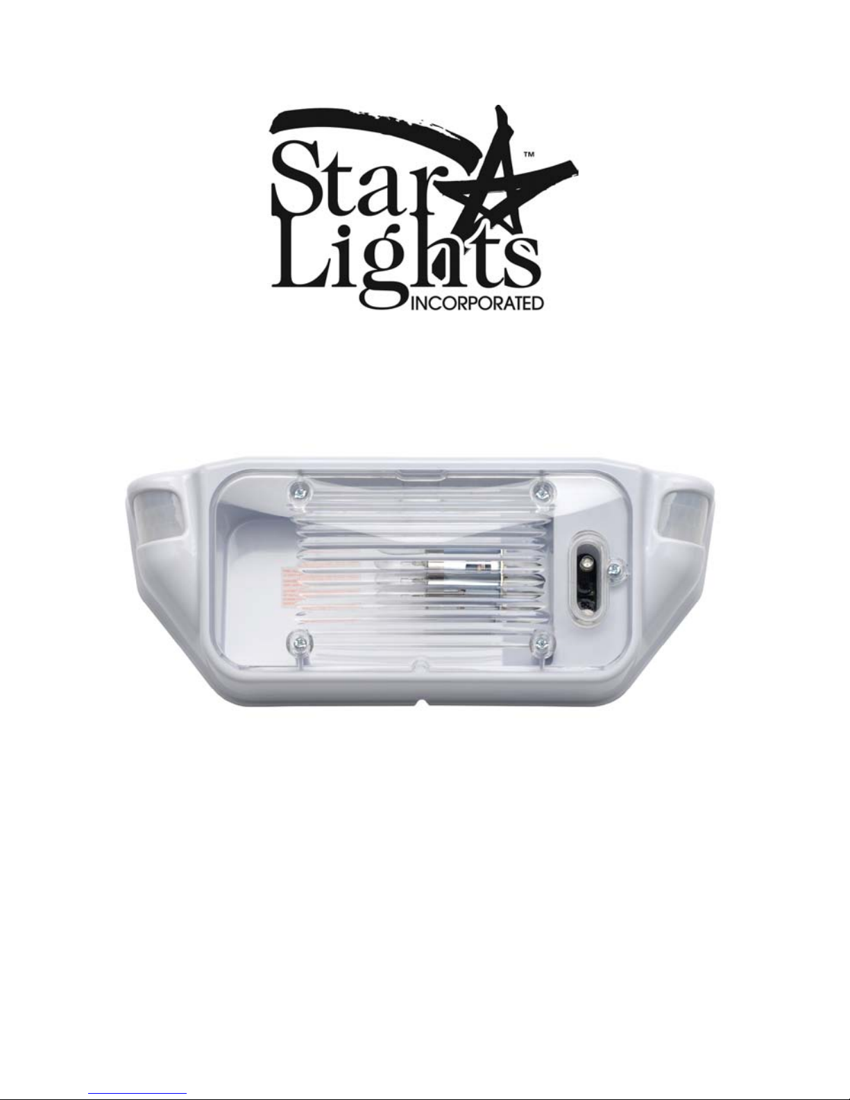
SMART LIGHT 1000™
INSTALLATION AND OPERATIONS
INSTRUCTIONS

- 2 -
REV-7.23.2012, CSA
THANK YOU FOR CHOOSING THE SMART LIGHT 1000™!
We are very pleased that you have chosen our product to enhance your camping
experience! At Starlights, Inc., we are passionate about improving your safety, security,
and convenience. We feel that the Smart Light 1000™represents a giant step forward in
improving an already wonderful experience –Rving!
Developed and designed in the United States, by RVers, for RVers, the Smart Light
1000™has the versatility to adapt to differing park conditions, or to dry camping
conditions. Your new Smart Light 1000™also monitors your battery levels, and will
notify you of any serious reduction in power. We are confident that you will be
completely satisfied with your new Smart Light 1000™for years to come. Happy
camping!
Jason P. Weaver
President, CEO
Starlights, Inc.
CONTENTS of Box
The Smart Light 1000™packaging should include the following parts to make the
installation simple and convenient.
1. One lighting fixture
2. Four mounting screws
3. 2ea. Butt connectors
4. Instruction Manual
BULB REQUIREMENT for the Smart Light 1000™--- Incandescent “1003” Bulb or
the NEW "Revolution LED line of Bulbs". This New line of LED Bulbs can be
reviewed at www.starlightsinc.com
OPTIONAL ACCESSORIES
Revolution LED Bulbs.
Smart Light 2000™Motion Light
Smart Light 2000 Scare Light™
Revolution 2000 FB™Fused Relay Box
Amberizer™Antibug Bulbs
Amber Lens
INSTALLATION & SAFETY INSTRUCTIONS
For the Smart Light 1000™RV Motion Light
IMPORTANT SAFETY INFORMATION
Disconnect battery before installing or replacing the motion sensor lighting
fixture.

- 3 -
REV-7.23.2012, CSA
This product must be installed in accordance with any state and national codes by
a person familiar with the construction and operation of the product and hazards
involved.
This motion sensor light is designed to be used only with 12 DC Power
[Automotive type], any modifications of the unit may result in a hazard and will
VOID the warranty.
Please do not attempt to open the Motion Sensor back housing as there are no
serviceable parts inside and doing so WILL VOID the warranty.
Please read all of the Smart Light 1000™installation instructions before
installing the fixture.
IMPORTANT NOTES
Attaching other accessories or devices without the uses of the Revolution 2000
FB™Fused Relay Box can cause a hazard, may damage the unit, and WILL
VOID the WARRANTY.
INSTALLING the Smart Light 1000™
IMPORTANT-DISCONNECT THE BATTERY
STEP 1: Remove the old lighting fixture from the RV and clean area of all old sealer,
dirt, etc.
STEP 2: Attach the BLACK or WHITE wire marked positive (+) on the SL-1000 fixture
to the positive wire (+) coming from the RV.
STEP 3: Attach the WHITE wire marked negative (-) on the SL-1000 fixture to the
negative wire (-) coming from the RV.
NOTE: If there are other accessories or devices that together total less than 4 amps that
you would like to trigger using the Smart Light 1000™you can trigger them by using
the Revolution 2000 FB™Fused Relay Box. The Revolution 2000 FB™Fused Relay
Box is triggered using the YELLOW wire located on the back of the fixture and will
supply voltage to the accessories while protecting the circuitry of the Smart Light
1000™.The YELLOW wire is shrink wrapped to the Power wire. To access the
YELLOW wire, remove the shrink wrap.
NOTE: Perform functionality test at this step
The Smart Light 1000™is reverse polarity protected. If it is wired backwards, the unit
will not be damaged. However, if wired incorrectly, the motion sensing functionality will
not work, even though the light can be turned on and off at the switch as with any other
porch light. Thus, it is imperative that you perform this self test in order to assure proper
functionality. To do this test you will have to reconnect the battery.
First, adjust your interior light switch to the on position. Then, turn the light switch off,
then on again. If at this point you find that the light turns on, but the BLUE LED does not

- 4 -
REV-7.23.2012, CSA
blink on and off, then switch the positive and negative wires connecting the Smart Light
to your vehicle. Next, perform the self test once again as described above. If your light
again fails to operate in the auto mode as indicated, please stop the installation process
and contact us at 1-800-883-5444. If the functionality test is successful, again
DISCONNECT THE BATTERY and proceed with the installation.
STEP 4: Remove the FIVE (5) screws that attach the lens on the Smart Light 1000™
fixture taking care not to lose the small O-ring on the backside of the lens
where the oval is and save them to reattach the lens in STEP (6). Place a bead
of silicone sealant on the backside of the fixture in the shear groove, being
careful not to plug the water drain groove at the bottom of the Smart Light
1000™fixture. Use the FOUR (4) screws provided, or the (4) screws from
your old fixture, to attach the Smart Light 1000™fixture to the exterior of the
RV. In most cases, the previous holes used to mount the old fixture can be
reused to mount the Smart Light 1000™. However, if you must drill new
screw holes into your substrate, make sure to properly fill in the old holes
before mounting your light.
STEP 5: Adjustment of the Variable Resistor (Potentiometers) for sensitivity is
clockwise to increase sensitivity, and counterclockwise to decrease sensitivity.
When adjusting this resistor, take care not to touch the mother board, which
could damage the unit and WILL VOID the WARRANTY. Please note that
the Smart Light 1000™fixture comes from the factory set at the most
sensitive setting and may need adjustment to a lower sensitive setting to match
the camping environment.
IMPORTANT –DISCONNECT THE BATTERY BEFORE ADJUSTING
The Potentiometers are located on the circuit board mounted in the electronics
compartment of the Smart Light 1000™fixture. Once the lens has been removed,
access for adjustment is through the opening, with the Potentiometers located above the
light sensor and below the multicolored LED. Note that the bottom potentiometer is for
the right sensor, and the top potentiometer is for the left sensor. Take great care when
adjusting not to touch the circuit board, which would void the warranty.
NOTE:
Some models may have differing hole depths and/or widths. Thus, the screws
provided may not be sufficient. If you find this to be the case on your model, simply
substitute the enclosed screws for those that will fasten the unit properly.

- 5 -
REV-7.23.2012, CSA
Please keep in mind outside temperatures when adjusting sensitivity.
PIR (PASSIVE INFRARED SENSOR) NOTE:
A note about this state of the art technology: These PIR sensors detect thermal mass.
Additionally, the internal micro processor embedded in your Smart Light 1000™
“communicates” with the PIR sensors in code. This code allows your Smart Light
1000™fixture to differentiate between a large thermal mass, and a small one (such as a
cat, rabbit, small dog, etc.). When a small thermal mass is detected, the code tells the light
not to turn on. When a larger mass is detected (i.e. humans, a bear, large dogs, etc.) the
code enables the unit to turn on the light. However, thermal readings are dictated by
outside temperatures. It is more difficult to trigger the fixture when the background
temperature is close to the outside body temperature of the object moving across it,
making it necessary to come closer to the fixture to turn it on. Likewise, if it’s very cold
outside, the cold background makes it much easier to pick up any thermal mass, and thus
the PIR sensors may detect an object further away than normal.
STEP 6: Replace the lens using the FIVE (5) screws removed in STEP (4).
VERY IMPORTANT: Please ensure that the CLEAR O-RING which seals the
electronics compartment is located properly on the back side of the Lens cover where the
oval is. If this small O-RING is missing when the cover is reinstalled, water may intrude
into the electronics compartment and disable the fixture. The O-RING is embedded in the
lens directly over the electronics compartment oval access hole. To ensure proper
placement of the O-Ring, rub your index finger around the outside of the oval portion of
the lens which covers the electronics compartment. If you are unable to locate the O-
RING, please contact us before installing the fixture.
You may now reconnect the Battery.
IMPORTANT NOTE:
The Smart Light 1000™fixture was designed to operate in two (2) modes:
Mode 1 –Manual Mode
The Manual mode is triggered when switched “ON” by the off-on switch located inside
the RV. In the manual mode, the daylight sensor will be inoperable and the Smart Light
1000™will work as a standard lighting product with the exception of Star Monitor™
Starlight's exclusive Star Monitor™will monitor the RV’s Battery Voltage Level. When
the voltage drops to 11.5 volts for 45 consecutive seconds, a RED led will blink behind
the lens as a warning of a low battery condition. Star Monitor™will not turn the Smart
Light 1000™fixture off in this mode, but it will issue a warning. As a side note, several
customers have called over the years claiming the Star Monitor™is inaccurate. Our
trouble shooting efforts found that every customer had some sort of electrical
malfunction. The Star Monitor™utilizes a digital code and is 99.999% accurate. Thus, if

- 6 -
REV-7.23.2012, CSA
you see the RED LED flash, please take care and check every facet of your electrical
system.
Mode 2 - Auto Mode
The Auto mode is triggered by an “ON-OFF-ON” switching of the off-on light switch
located inside the RV. However, if the fixture is already powered up in Manual Mode,
then switching the fixture “OFF then ON” will trigger the Auto Mode function. In the
Auto Mode, the daylight sensor, Star Monitor™,and motion sensors are operable. Once
the Smart Light 1000™detects motion it will activate the bulb and stay on for one
(1) minute. If the fixture again detects motion before the (1) minute is up, then the
timer will reset, and the count-down will recommence. If no other motion is
detected, then the light will deactivate, and the area around your coach will continue
to be monitored. Finally, don’t be alarmed if the Smart Light 1000™does not detect
your motion at the exact same point each time. A variety of factors dictate when and at
which point the motion detection units will activate the light bulb. If you have questions
about this nuance, please contact our engineering help desk for a more thorough
explanation.
Starlight’s’ exclusive Star Monitor™continues to monitor the RV’s Battery Voltage
Level. If the voltage drops to the predetermined level, a RED LED will blink behind the
lens as a warning of a low battery condition. Star Monitor™will, in the auto mode, turn
the Smart Light 1000™fixture off. When the battery rises past the predetermined level,
the Smart Light 1000™fixture will reset itself automatically and continue operation.
Side note: Customers have asked why we deactivate the Smart Light 1000™at 11.5
volts. The reason is that at this voltage level, most of your major appliances will cease to
operate (such as your refrigerator). Also, at 11.5 volts, your batteries are working at less
than 35% capacity.
The Smart Light 1000™has three (3) operating phases as listed below:
1. When activated in the “DAY-TIME Auto Mode”function, the Multi-
Colored LED will blink “BLUE”.This indicates that the fixture is
activated, it is daytime, your battery is charged, and that the unit will not
illuminate if it senses motion.
2. When activated in the “NIGHT-TIME Auto Mode”function, the Multi-
Colored LED will blink “GREEN”.This indicates that the unit is
activated, it is dark outside, your battery is charged, and that the light will
illuminate if the proper motion is detected.
3. When the Smart Light 1000™fixture is in either mode and the Star
Monitor™function has been activated by a low battery condition, the
Multi-Colored LED will blink “RED”.Regardless of the time of day, the
light will not illuminate with any motion until the low battery condition is
remedied.

- 7 -
REV-7.23.2012, CSA
Smart Light 1000™Trouble Shooting Guide
SYMPTOM
CAUSE
POSSIBLE SOLUTION
Light won't
come on.
•
Power not on.
•
Turn on indoor switch or check fuse.
•
Grounded incorrectly.
•
Check ground wire.
•
Light bulb blown.
•
Check bulb and replace if necessary.
While in
Porch Light
Mode the
LED flashes
"RED" but
the Light
Bulb does
work.
•
Low Battery Condition -
(Line Voltage to fixture
dropped to 11.5 Volts or
below for a period of 45
seconds).
•
Charge or replace the Coach the Battery.
•
Check breaker on Coach charging system and reset if
necessary.
•
Too much load on wire
supplying power to the
fixture.
•
Up-size wire gauge from distribution panel to Fixture.
•
Up-size wire gauge to distribution panel from battery.
Smart Light
1000™only
works as a
Porch light
•
SL1000™wired wrong
•
Switch power leads to fixture.
Light stays
on in AUTO
MODE.
•
Fixture operating in
PORCH LIGHT MODE.
•
Re-program with indoor switch.
•
Wired incorrectly.
•
Check that wiring is connected properly.
•
Frequent changes in heat
are being detected.
•
Check sensing area for possible heat sources i.e. water heater
exhaust, moving vehicles, or other heat source. Adjust the
sensitivity to a less sensitive setting.
SL1000™will
not energize
the bulb in
auto mode
when there
is motion
within the
detection
area
•
The SL1000™is blinking
"BLUE" not "GREEN"
•
Wait until night time, as the SL1000™will not change modes
until the outside light has dropped to a certain Luminous
level.
•
Make sure that a street light, parking lot lighting or other
bright light is not directly shinning on the fixture.
•
Wait until the fixture has time to determine which mode to
operate in. It always defaults to daytime mode once
triggered and takes 30 seconds to change modes.
Light keeps
cycling
"ON" &
"OFF"
Changes in heat are
being detected from a
fixed heat source
Check the field of view for hot gas vents, camp fires, or other
heat sources. If possible, reposition your coach.
Light and Heat are
being reflected back
onto the sensor
Mask reflective surfaces to eliminate the reflection, or
reposition the coach if possible.
Sudden temperature
changes due to storms
or high winds or rain
Turn sensor off until storm passes.
While in
"Auto
Mode" the
LED flashes
"RED" but
the Light
Bulb does
"NOT"
Work.
Low Battery Condition
- (Line Voltage to fixture
dropped to 11.5 Volts or
below for a period of 45
seconds).
Start the generator if applicable. Otherwise, charge or
replace the Coach the Battery.
Check breaker on Coach charging system and reset if
necessary.
Too much load on wire
supplying power to the
fixture.
Up-size wire gauge to distribution panel from battery.

- 8 -
REV-7.23.2012, CSA
LIMITED WARRANTY
This product is warranted free from defects in material and workmanship for a period of one year. If a defect in material or
workmanship occurs, call (805) 685-8500 or (800) 883-5444 for instructions on how to have the defective product repaired
or replaced.
LIMITATIONS
This warranty is extended only to the original purchaser of the product.
This warranty only covers the assembled motion lighting fixture.
Unauthorized service to, or modification of this product will void the warranty in its entirety.
Apurchase receipt or other approved proof of purchase is required before warranty service is rendered.
This warranty is expressly in lieu of all other warranties, expressed or implied, including any warranty, representation or
condition of merchantability or that the products are fit for any particular purpose or use, and specifically in lieu of all special,
indirect, incidental, or consequential damages, including but not limited to, any loss arising out of any breach of this warranty,
as allowed by your state of domicile.
This warranty gives you specific rights, and you may also have other rights that vary from state to state.
NOT COVERED
Failure of the product as a result of an accident, abuse, negligence, alteration, or faulty installation, or any other failure not
relating to faulty material or workmanship.
Reimbursement for inconvenience, installation, setup, time, loss of use, postage or unauthorized service.
CAUTION: This unit should yield many years of quality service. However, to avoid damaging the
Smart Light 1000™fixtures Fresnel lenses and sensors, do not spray the Smart Light 1000™fixture
directly with a high-pressure hose, or pressure washer.
GENERAL CORRESPONDENCE
Starlights, Inc.
PO Box 80246
Goleta, CA 93118
Phone (805) 685-8500
Phone (800) 883-5444
Fax (805) 685-3754
T
TH
HA
AN
NK
KY
YO
OU
UF
FO
OR
R
Y
YO
OU
UR
RT
TR
RU
US
ST
TI
IN
NU
US
S!
!
RETURNS:
Starlights, Inc.
283 Pamela Way,
Unit 104
Buellton, CA 93427
For technical issues:
Gregg Wilson
gregg.w[email protected]
If it is necessary to return any Starlight product, please get a RETURN CONFIRMATION NUMBER by calling
(805) 685-8500 or (800) 883-5444.Then send the unit back in its original box with all original parts, as well as a
copy of your receipt and a brief explanation of what kind of failure you experienced, to the address below.
Table of contents
Popular Home Lighting manuals by other brands


Philips
Philips 322011116 user manual

Springdale Lighting
Springdale Lighting GT15317LED Assembly instructions

OttLite
OttLite J8600C manual

Maretti
Maretti PIETBOON STACK WALL E27 quick start guide

JONATHAN Y
JONATHAN Y JYL2068A quick start guide

Safavieh Lighting
Safavieh Lighting MODERN LIT4504A quick start guide