Steffes DLF30B User manual

DLF4
OWNER'SAND
INSTALLER'SMANUAL
for
DoubleLoop(Central)Furnaces
"Manufactured in North America"
U.S. Pat. #5201024
Can. Pat. #2060881
Models:DLF30B&DLF40B

General Information
GeneralOperation .................................................................................................................................................................... 2
Terminology............................................................................................................................................................................ 3
Safety Information
SafetyPrecautions ................................................................................................................................................................... 4
BuiltinSafetyDevices............................................................................................................................................................ 4
Maintenance and Cleaning........................................................................................................ 4
Furnace Control Panel................................................................................................................... 56
Operating the Furnace
FurnaceStartup ...................................................................................................................................................................... 7
RoomTemperatureControl...................................................................................................................................................... 7
BrickTemperatureControl(CoreCharging)........................................................................................................................... 78
HowtoTurntheFurnace"OFF"and"ON".............................................................................................................................. 8
Installing the Furnace
Shipping................................................................................................................................................................................. 9
Placement ................................................................................................................................................................................ 9
ClearanceRequirements ......................................................................................................................................................... 10
FurnaceSetup..................................................................................................................................................................1012
BrickLoading....................................................................................................................................................................1213
InstallingtheHeatingElements .............................................................................................................................................. 13
Ducting .............................................................................................................................................................................1314
LineVoltageElectricalConnections ...................................................................................................................................1518
LowVoltageElectricalConnections...................................................................................................................................1922
FurnaceFinalTestProcedure ................................................................................................................................................. 23
Furnace Specifications................................................................................................................... 24
Exploded View Parts Diagram ............................................................................................... 25
Furnace Parts List...............................................................................................................................2627
Troubleshooting Information
BrickCoreTemperatureTesting............................................................................................................................................. 28
TroubleshootingGuides....................................................................................................................................................2934
Warranty
Table of Contents
1

• ThismanualprovidesinformationforcorrectinstallationproceduresandelectricalconnectionsforSteffesETS
DoubleLoopFurnaces,ModelsDLF30BandDLF40B.Theinformationinthismanualwillhelpyouutilizethe
product'smanyfeaturesandensuremanyyearsofsafe,reliableoperation.Readalltheinformationcontained
withinthismanualbeforeinstallingthesystem.Storethismanualinasafeplaceforfuturereference.
• Assemblyofand/orservicetotheseunitsshouldbeperformedonlybyaqualifiedelectricianinaccordancewith
informationcontainedhereinandinaccordancewithnational,state,andlocalelectricalcodes.
• Thismanualmustberetainedbynewownersifownershipofthefurnacechanges.
• Anydeviationfromtheseinstructionsmayvoidthewarrantyandcouldresultinhazardousoperatingconditions.
• Thewarrantyregistrationcardprovidedaspartoftheunitdocumentationsetmustbecompletedandreturnedto
SteffesCorporation.Failuretodosomayadverselyaffectwarrantyclaims.
• Recordtheserialnumberandmodelnumberinthespacesprovidedonthebackpageofthismanual.These
numbersarelocatedontherightsideofthefurnacebase,ontheshippingbox,andonthewarrantyregistration
card.Retainthismanualforaquickreferencetothesenumbers.
• DISCLAIMER: Incompilingthismanual,SteffesCorporationhasuseditsbestjudgementbaseduponinfor
mationavailablebutdisclaimsanyresponsibilityorliabilityforanyerrorsormiscalculationscontainedherein,or
anyrevisionshereof,orwhichresult,wholeorinpart,fromtheuseofthismanualoranyrevisionshereof.
2 General Information
GENERAL OPERATION
TheSteffesETSDoubleLoopCentralFurnace(DLF)utilizesoffpeakelectricitywhichisavailableduring
timesofthedayornightwhenthepowercompanycansupplyelectricitymoreeconomically.Byusingthisoff
peakelectricityforheating,thepowercompanymayofferaspecialincentivesuchasareducedelectricrate,
anoffpeakheatingrate,atimeofuse(TOU)rate,ormonthlycreditsonyourheatingbill.
Whenoffpeakhoursareavailable,thefurnaceconvertselectricitytoheatwhichisthenstoredinitsceramic
brickcore.Theamountofheatstoredinthebrickcorevariesinrelationtooutdoortemperature,owner
preference,utilitypeakconditions,andtherequirementsofthespacebeingheated.Thisstoredheatbecomes
availableforspaceheatingneedsasdeterminedbythewallthermostatthatisstrategicallylocatedintheliving
space.
Whenthewallthermostatsensesaneedforheat,thecoreblowerandsupplyblowerinthefurnaceoperate.
Thecoreblowercirculatesthehotbrickairandwarmstheheatexchangerlocatedinthebaseofthefurnace.
Thesupplyairblowercirculatesroomairthroughtheexchangerwhereitisheatedandthendeliversittothe
conditionedspace.
1

Automatic Charge Control Methodofbrickcorechargeregulationwhereasensormonitorsoutdoor
temperaturetoautomaticallyadjustthebrickcoretemperaturesettinginrelation
totheoutdoortemperature.
Brick Core Charge Level Theamountofheatthatisstoredintheheater’sbrickcore.
Charge Period Offpeaktimeinwhichthefurnaceisallowedtostoreheatinitsbrickcore.
Control Panel Containsthetoggleswitchestoadjustanddisplaylightstoindicatefurnace
operation.Locatedonthelowerfrontofthefurnaceontheelectricalpanel.
Control Period Onpeaktimeinwhichthefurnaceisnotallowedtostoreheatinitsbrickcore.
Heat Call Whenroomtemperaturefallsbelowtheroom’sthermostatsetting,thethermo
statsignalsthefurnacetooperateitsblowersanddeliverwarmairintothe
spacetoraisethetemperaturetothedesiredthermostatsetpoint.
Heat Exchanger Deviceinthebaseofthefurnacewherethestoredheatfromthebrickcore
transferstotheductsystemfordeliveryintothelivingspace.
Manual Charge Control Methodofbrickcorechargingregulationwheretheusermustperiodicallyadjust
thebrickcoretemperaturesettinginrelationtotheoutdoortemperature.
OffPeak Thetimeduringthedayornightwhenthepowercompanycansupplyelectricity
moreeconomicallyandmayofferaspecialincentivesuchasareducedelectric
rateorbillingcreditsfortheelectricityconsumedduringthistime.Typically,
uncontrollableelectricalusageisallowedduringthistime.(Furnaceisallowed
tochargeorstoreheatinitsbrickcoreduringthistime.)
OnPeak Thetimeduringthedayornightwhenthepowercompanyexperiencesahigh
demandforelectricity.Tolimitdemand,certainappliancesarecontrolledto
avoidusagebythemand/orapremiumfortheelectricityconsumedduringthis
timemaybecharged.(Furnaceisnotallowedtochargeorstoreheatinits
brickcoreduringthistime.)
Outdoor Temperature Sensor Devicethatsensesoutdoorairtemperatureandcommunicatesthisinformation
tothefurnaceforautomaticchargecontrol.
Peak Override Enableselectricalusageinadevicethatistypicallycontrolledbythepower
companyduringanonpeaktime.Somepowercompaniesmayneverpermit
anycontrolleddevicestobeusedduringanonpeaktime.Othersthatdomay
penalizetheuserbychargingapremiumonenergyconsumedduringthisperiod.
3
General Information (cont'd)
TERM DEFINITION
TERMINOLOGY
Thismanualcontainstermswhichmayneedexplanation.Thetablebelowlistssomeofthesetermsandabrief
descriptionofeach.
2

DEVICENAME FUNCTION
Safety Information
LOCATION
ON HEATER
SAFETY PRECAUTIONS
1. DONOTenergizethefurnacewhiledisassembledorwithoutceramicheatstoragebrickinplace.
2. Asistruewithallheatingappliances,materialsthatmayproduceexplosiveorflammablegasesMUSTNOT
beusedorstorednearthefurnace.
3. Besuretheminimumclearancerequirementsspecifiedinthismanualareneverviolated.
4. Thisunitmaybeconnectedtomorethanonebranchcircuit.Disconnectpowertoallcircuitsbeforeservicing.
BUILT-IN SAFETY DEVICES
AllSteffesDoubleLoopCentralFurnacesincorporatesafetydevicestoensurenormaloperatingtemperatures
aremaintained.The chart belowdescribesthesesafetydevices.
4
CoreChargingHigh
LimitSwitches
Theselimitswitchesmonitorbrickcorechargingandwill
interruptpowertotheheatingelementsifthenormal
operatingtemperatureisexceeded.Eachswitchcontrols
two heating elements.
Inthelimitbarpanel
ontherightsideofthe
brickstoragecavity
Thislimitswitchmonitorsthetemperatureintheheat
exchangerofthefurnace.Ifthenormaloperatingtempera
tureisexceeded,thisswitchwillinterruptpowertothecore
blower.
Heat Exchanger High
LimitSwitch
Inthebaseofthe
furnaceinsidethe
electricalpanel
Thislimitswitchmonitorsthedischargeairtemperatureand
interruptspowertothecoreblowerifthistemperature
exceeds160
o
F(nominal).
CoreBlower High
LimitSwitch
Inthesupplyair
plenumassemblyon
theblower
Thislimitswitchmonitorsthedischargeairtemperatureand
interruptspowertothesupplyairblowerifthistemperature
exceeds180
o
F(nominal).
SupplyAirBlower
LimitSwitch
Inthesupplyair
plenumassemblyon
theblower
2
Thefilterinthefurnaceshouldbereplacedonaregularbasis.Generalcleaningofthefurnace’scabinetshouldbe
conductedattheuser’sdiscretion.Noadditionalroutinemaintenanceisrequired.
Maintenance and Cleaning
1

Furnace Control Panel 5
Furnaceoperationisautomatic;however,theusercanmanuallyoperateitbychangingsettingsonitscontrolpanel.
(SeeFigure1forreferencetolocationofthecontrolpanelandcircuitbreakersonthefurnace.)
FIGURE 1
POWER ON Light
Thisgreenindicatorlightilluminateswheneverthefurnaceisenergized.
OFFPEAK Light
Thisredindicatorlightilluminatesduringoffpeaktimeswhicharethetimeswhenthefurnaceisallowedtocharge.
(Elementscanbe"ON"tostoreheatinthebrickcore.)
HEAT CALL Light
Thisyellowindicatorlightilluminateswheneverthefurnaceisreceivingasignalfromthewallthermostattodeliver
heat.
ETSCHARGING Light
Thisredindicatorlightilluminateswhenevertheheatingelementsinthefurnaceare"ON".(Furnaceisstoringheatin
itsbrickcore.)
OUTDOOR TEMP SENSOR Lights
Theseredindicatorlightsilluminatetodesignatethebrickcorechargelevelthefurnaceistargetingwheneverthe
elementsareallowedtobe"ON".(RefertoTable1,BrickCoreChargingSchedule,inthismanualformoreinforma
tiononcharginglevelsinrelationtooutdoortemperatureandthefurnacecontrolpanelsettings.)
LEVEL1 = Illuminateswhenthefurnaceistargetingaheatstoragesettingofapproximately1/3corecharge
(500
o
F,nominal)orgreater.
LEVEL2 = Illuminateswhenthefurnaceistargetingaheatstoragesettingofapproximately2/3corecharge
(900
o
F,nominal)orgreater.
LEVEL3 = Illuminateswhenthefurnaceistargetingitsmaximumheatstoragesetting(1350
o
F,nominal).
All outdoor temperature sensor lights will be illuminated when the furnace is targeting
its maximum heat storage setting.
FURNACECONTROL
TEMPSENSOR
OUTDOOR
OVERRIDE
START
SUMMER
WINTER
CANCEL
HIGH
LOW
LEVEL3
LEVE L2
AUTO
PANEL
ETSCHARGING
HEATCALL
OFFPEAK
POWERON
LEVEL 1
CIRCUITBREAKERSCIRCUITBREAKER
BLOWERS/FURNACECONTROLS CORECHARGING(ELEMENT)
SUPPLYAIRBLOWER
PLENUMASSEMBLY
WITHHEATEXCHANGER
FURNACEBASE
NOTE

6 Furnace Control Panel (cont'd)
SUMMER/WINTER Toggle Switch
Thistoggleswitchwillvarycorecharginginthefurnace.Itallowsforareducedheatingcapacityduringthesummer
monthsiftheuserpreferstoleavethefurnace"ON"foremergencyheatpurposesduringthistime.(RefertoTable1,
BrickCoreChargingSchedule,inthismanualformoreinformationoncharginglevelsinrelationtothepositionofthis
switchandoutdoortemperature.)
AUTO/HIGH/LOW Toggle Switch
Thistoggleswitchcanbeusedtooverridetheautomaticoutdoortemperaturesensingsystem.
AUTO= Normaloperatingposition.Thebrickcorechargeleveliscontrolledautomaticallybytheoutdoor
temperature sensor.
HIGH = Thefurnacewilltargetalevel3(maximum)corechargeduringanoffpeaktimeregardlessofthe
outdoortemperatureinformationitisreceiving.
LOW = Thefurnacetargetsaminimumofalevel1(1/3)corechargeduringanoffpeaktimeunlessthe
outdoortemperaturesensorissignalingforahigherchargelevel.
OVERRIDE Light (Power Company Permitting)
Thisredlightilluminateswheneverapeakcontroloverrideisinitiatedandremainsilluminatedforthedurationofthe
overrideperiod.ThefunctionoftheoverrideindicatorlightworksinconjunctionwithSTARTandCANCELtoggle
switches.
START and CANCEL Toggle Switches (Override Feature, Power Company Permitting)
Thefurnacehasabuiltinpeakoverridefeature.Thisfeatureallowstheheatingelementsinthefurnacetocome"ON"
duringapeakcontroltimeprovidedthepowercompanypermitstheuseofthisoption.Sincenotallpowercompanies
permituseoftheoverrideoption,allfurnacesareshippedwiththisfeaturedisabled.Ifthefeatureisenabledinthe
furnace,thesetoggleswitchesinitiateandcanceltheoverrideofapeakcontroltime.
START = Initiatesanoverrideofapeakcontroltimeallowingtheheatingelementstocome"ON".The
furnacetargetsalevel1(1/3)corechargeduringanoverridecycle.Ifinitiatingthepeak
controloverridefeature,theoverridewillonlylastforthedurationofthepeakcontrolperiodat
whichtimeitresetsitselfautomaticallyunlesstheusermanuallycancelsitpriortothen.(The
overridelightwillillumniateiftheSTARTswitchistoggled.)
CANCEL = Allowsformanualcancellationofapeakoverrideanytimeduringanoverridecycle.An
overridecyclewillautomaticallycancelitselfatthestartofthenextoffpeakperiod.
The peak override option may not be available in your area. Please consult your power
company if you are unsure of whether this option is available to you. If so and you desire
to enable the feature, contact your power company for instructions.
NOTE

FURNACE START-UP
Onstartupofthefurnace,youmayexperiencesomeodorsrelatingtofirsttimeoperationoftheheatingcompo
nents.Theremayalsobeanodorassociatedwithdustaccumulationinthesystemifthefurnaceisshutdownfor
anextendedperiodoftime.Uponrestart,allowingthefurnacetochargetoitsmaximumbrickcorechargelevel
willhelpexpeltheseodorsinatimelymanner.
Duringoperation,itisnormalforthefurnace,likeanyheatingsystem,toproduceexpansionnoises.Thesenoises
aretheresultoftheinternalcomponentsreactingtothetemperaturechangestheyareexposedto.
ROOM TEMPERATURE CONTROL
Roomtemperatureisadjustedatthewallthermostat.Withaheatcalltothethermostat,thecoreblowerinthe
furnaceisenergizedtocirculatehotbrickcoreairthroughthefurnace’sheatexchanger.Thecoreblower
automaticallyadjustsits'speed(loworhigh)inrelationtothebrickcoretemperature.Thebloweroperatesinlow
speedwithahotbrickcoreandinhighspeedwithlowerbrickcoretemperatures.
Afterthebrickcoreairwarmstheheatexchanger,thesupplyairblowerisenergized.Thesupplyairblower
circulatestheroomairthroughtheheatexchangertowarmit;and,then,deliversitbackintothelivingspace
throughtheductsystem.
Thedelaybetweenthecorebloweroperatingandthesupplyairblowerbeingenergizedensuresonlywarm,
comfortable,evenheatisbeingdeliveredintothelivingarea.Intermittentsupplyairbloweroperationmayoccur
withlowerbrickcoretemperaturesinanefforttomaintainaconstanttemperatureandevendistributionofheat
intothelivingarea.
Somethermostatsincorporatearoomtemperaturesetbackfeaturewhichallowsforroomtemperatureto
automaticallybesetbackaspecificnumberofdegreesatspecifiedtimes.Ifusingathermostatwiththisfeature
inaprogramwherethepowercompanyhas8ormoreconsecutivehoursofcontrol,itisimportanttobringthe
roomtemperaturebacktothedesiredoccupiedtemperatureaminimumofthree(3)hoursbeforetheoffpeak
(charge)periodends.Thiswillensureoptimumheatstorageformaintainingthedesiredroomtemperature
throughouttheonpeak(control)period.
BRICK TEMPERATURE CONTROL (CORE CHARGING)
Theamountofheatstoredinthebrickcoreofthefurnaceisregulatedautomaticallyinrelationtooutdoortem
peratureandtoitscontrolpanelsettings.Theoutdoortemperaturesensorthatshipswiththefurnaceasstandard
equipmentMUSTbemountedoutside.Itprovidestemperatureinformationtothefurnaceforproperbrickcore
charging.
Instandardconfigurationfromthefactory,theoutdoorsensorsignalsthefurnacetomaintainalevel1(1/3)brick
corechargeata55
o
Foutsidetemperature,alevel2(2/3)corechargeat35
o
F,andalevel3(maximum)core
chargeat15
o
F.Attemperaturesabove55
o
F,thefurnacewillnotmaintainacorecharge;however,ifthereisa
heatcallfromthethermostatduringoffpeaktimes,1/3oftheelementswillbeenergizedtoprovideheatforthe
durationoftheheatcall.(RefertoTable1,BrickCoreChargingSchedule,formoreinformationoncharging
levelsinrelationtooutdoortemperatureandthefurnacecontrolpanelsettings.)
If outdoor temperature charging set points other than the standard configuration are pre
ferred, the sensor must be specially ordered from the factory.
Operating the Furnace 7
2
3
1
NOTE

SUMMER/WINTER OUTDOORAIR CHARGE kWINPUT(MAX) CORETEMP.
SWITCHPOSITION TEMP.(ºF) LEVEL DLF30B DLF40B ºF(Nominal)
Winter 55* 1 9.6 12.8 500
Winter 35 2 19.2 25.6 900
Winter 15 3 28.8 38.4 1,350
Summer 35 1 9.6 12.8 500
Summer 15 3 28.8 38.4 1,350
Operating the Furnace (cont'd)
8
HOW TO TURN THE FURNACE “OFF” AND “ON”
Sinceheatcallsareunlikelyduringthesummermonths,youmaywishtoturnthefurnace"OFF".Todoso,
switchall60ampcorechargingbreakerslocatedonthefrontofthefurnace’selectricalpaneltothe"OFF"
(down)position.(SeeFigure1forreferencetothelocationofthebreakersonthefurnace.)The15amp
breakershouldremain"ON"atalltimesasthisbreakeroperatestheblowersandallothercontrolsinthefurnace.
ItMUSTremain"ON"ifusingthefurnaceinconjunctionwithanairconditioningsystem.Toturnthefurnace
"ON",switchthebreakerstotheUPposition.
Foruserswhoprefertomaintainareducedheatingcapacityduringsummermonthsratherthanshuttingthe
systemoffcompletely,theSUMMER/WINTERtoggleswitchshouldbesettotheSUMMERposition.In
standardconfiguration,aSUMMERswitchsettingenablesautomaticbrickcorechargingbutatareducedlevel.
Theoutsidetemperaturemustdropbelow35
o
Fbeforecorechargingwilloccur.(RefertoTable2,BrickCore
ChargingSchedule,inthismanualformoreinformationoncharginglevelsinrelationtooutdoortemperatureand
thefurnacecontrolpanelsettings.)
* Ifduringoffpeakhoursthewallthermostatcallsforheatandtheoutdoortemperatureisabove55
o
F,1/3of
theelementswillbeenergizedforthedurationoftheheatcall.
BRICK CORE CHARGING SCHEDULE
Table 1
Duringbrickcorecharging,theheatingelementsarestaged"ON"and"OFF"in6.4kWincrements(maximum).
4
TheAUTO/HIGH/LOWtoggleswitchonthefurnacecontrolpanelwillallowtheusertooverridetheautomatic
chargecontrolsystemofthefurnace.Innormaloperation,thisswitchissettotheAUTOpostion.Regardlessof
thepositionofthisswitch,thebrickcorechargingsysteminthefurnaceisdesignedtorespondtothecoldest
temperaturesignalitisreceiving.Asaresult,ifthetoggleswitchissettoLOWandtheoutdoorsensoriscalling
forahigherbrickcoretemperaturesetting,thefurnacewillrespondtothesensorsignal.Or,shouldthecharge
level1sensorfailtorespondtooutdoortemperature,thechargelevel2or3sensorswillinitiatecorecharging.
Thisfeatureprovidescontrolredundancywhichreducesthechanceofhavinganunchargedorundercharged
brickcoreduringcoldweather.

18"
491/2"
30"
551/2"
693/4"
DLF40B 21"
511/2"
TOPVIEW
241/2"
33/4"
SLOTFOR
16"X25"FILTER
RETURNAIRDUCTIS241/2"X15"
60"
Installing The Furnace 9
1 SHIPPING
Thefurnaceisshippeddisassembledforeaseinhandlingandmovingintolocationwhereitistobeinstalled.
(RefertoTable2forinformationontheitemsshippedwitheachfurnace.)
Table 2
MODEL BRICK ELEMENTS DUCTING
(See Note 1) (See Note 2) (See Note 3)
DLF30B 28boxesWholeBrick(3/Box) 9 1BoxReturnAirFilterRack
2boxesHalfBrick(6/Box) 1BoxSupplyAirBlowerPlenumAssembly
1 Hardware Package (See Note 4)
DLF40B 37boxesWholeBrick(3/Box) 12 1OutdoorTemperatureSensor(SeeNote5)
2boxesHalfBrick(6/Box)
NOTES: 1. The furnace ships in two sections (brick storage cavity and base assembly) banded
to one pallet.
2. Each brick box weighs approximately 72 lbs each.
3. The elements are shipped inside the brick storage cabinet of the furnace.
4. The hardware package is shipped in the base assembly portion of the furnace.
5. The outdoor temperature sensor is shipped in the supply air blower plenum assem
bly box.
PLACEMENT
Thephysicaldimensionsofthefurnacealongwiththeclearancesrequiredmustbetakenintoconsideration
whenchoosingalocationforthefurnace.Theminimumareaneededfortheinstallationofafurnaceis100
squarefeet.Thebestinstallationlocationforthefurnaceisinanareaitwillbeheating.Althoughmostofthe
heatingrequirementsofthespacewillbesatisfiedbytheheatdeliveredthroughtheductsystem,asmallamount
oftheheatingrequirementswillalsobesatisfiedthroughstaticheatdissipatingthroughthefurnace'swarm
outsidepanels.Insituationswherethefurnacewillnotbeinstalledintheareaitisintendedtoheat(i.e.garage),
itisimportanttoaccountfortheheatlostthroughitspanelsbymakingproperadjustmentsinsizingofthe
furnace.
Inadditiontothephysicalspacerequirements,theweightofthefurnacemustalsobetakenintoconsideration
whenselectingtheinstallationsurface.Alevelconcreteflooristhebestsurfaceonwhichtoplacethefurnace,
butmostwellsupportedsurfacesareacceptable.Ifindoubtaboutfloorloadcapacity,consultabuildingcon
tractororarchitect.(SeeFigure2forfurnaceandductingdimensions.)
2
FIGURE 2

0" REQUIRED
CLEARANCE
2" MIN
CLEARANCE
3" MIN CLEARANCE
36" MIN CLEARANCE
TOP VIEW
0" REQUIRED
CLEARANCE
6" MIN
CLEARANCE
Installing The Furnace (cont'd)
10
CLEARANCE REQUIREMENTS
Theminimumclearancesrequiredwheninstallingthefurnaceinto
anyareaareasfollows:
BackandSides=3inches(fromcombustiblematerial)
Top=6inches(fromcombustiblematerial)
Front=36inches(foreaseofservicing)
FurnaceRightSideandAirDuct=2inches
FurnaceLeftSideandAirDuct=zeroclearance
SidesofFurnaceDucts=zeroclearance
Theclearanceareasmustbekeptopenandfreeofdebris.Donot
placeanythingontopthefurnace.Ifthefurnaceisinstalledina
small,enclosedarea(lessthan400squarefeet),theareamustbe
wellventilated.Forventilationpurposes,aminimumofa24”X24”
openingmustbeinstalled,ifnotalreadypresent,intotheareawhere
thefurnaceislocated.Inaddition,a6”X6”nonclosingtype
registermustbecutintothereturnairductofthefurnacetominimize
heatbuildupintheroom.(SeeFigure3foradepictitionofclearance
specifications.)
3
FIGURE 3
FURNACE SET-UP
For cross reference to number coded components, see
the Exploded View Diagram and the Furnace Parts List
in this manual. Refer to Table 2 in the Shipping section
of this manual for a list of items each furnace should
contain.
Step 1 Unboxthebrickstoragecabinet
Step 2 Removepaintedfrontpanel(11)ofcabinetbyremovingthesheetmetalscrewsontheloweredge.
Rotatebottomedgeofpanelouttodetachitfromthecabinet.
Step 3 Ontherightsideofthecabinet,removethescrewsaroundthelimitbarlouvrepanel(63).(See
Figure4forreferencetothelocationofthispanelandthescrews.)
Step 4 Slidethesidesandbackpaintedouterpanels(9,71,&73)backwardsasoneassemblyandremove
fromcabinet.
Step 5 Usethehandlesonthebrickstoragecabinettomoveittoitsinstallationlocation.Setasidefornow.
Removal of the limit switches (67) on the
right side of the brick storage cabinet
may be necessary to avoid damage to
these switches during the move.
Step 6 Removethebaseassembly(50)fromitsboxandmove
ittotheinstallationlocation.Discardthewooden
packagingfromthetopofthebase.Locateandset
asidethehardwarepackageshippedontopofthebase
assembly.
Do NOT install the furnace on its
shipping pallet.
4
FIGURE 4
NOTE
NOTE
NOTE
BrickStorage
Cabinet

Installing The Heater (cont'd) 11
Step 7 Adjustthelevelinglegs(48)onthebottomofthebaseassembly(50)onceitissetinfinalposition.
The leveling legs must not be extended more than one inch. The base MUST
set securely on all four legs to prevent rocking of the furnace and/or twisting of
the heat exchanger.
Step 8 Setthebrickstoragecabinetonthebaseassembly(50)takingcarenottodamagethewiringhar
nesses(65&70).
The rope gasket around the
heat exchanger inlet
and outlet of the base
assembly must be
properly adhered and
free from damage.
Damage to any
gasketing on the
furnace will result in
improper unit opera
tion and/or furnace
damage.
Step 9 Positionwiringharnesses(65&70),
andtemperaturesensingbulband
plateassembly(77)tofacilitate
routingthroughbottomrightside
panelcutout.(SeeFigure5for
referencetowiringharnesslocations
on the furnace.)
Step 10 Installthesidesandbackpainted
outerpanels(9,71&73)onthe
brickstoragecavity.Usethescrewsfoundinthehardwarepackagetosecurethepanelstothe
cabinetbyplacingthemalongbottomedgeofthepanels.
To avoid internal wire damage, use only blunt tip screws in all areas where
screw tips could come in contact with wiring.
Step 11 Installthetemperaturesensingbulbandplateassembly(77)bytighteningthescrewsinacross
patternuntilgasketiscompressed.Donotovertighten.Makecertainthatthecapillarytubeofthe
temperaturesensingassembly(77)doesnotcomeintocontactwithanyliveelectricalterminals.
Failure to seal the sensing bulb plate will cause abnormal furnace operation and
potential component damage.
Step 12 Connectthemainandelementwiringharnesses(65&70)tothelimitswitches(67).Theswitches
aremarkedwithareddotononeside.Connecttheredwirestothereddotmarkedsideofthe
switches.Connecttheblackwirestotheunmarkedsideoftheswitches.
NOTE
NOTE
NOTE
NOTE
FIGURE 5

Installing The Heater (cont'd)
12
Step 13 Connectthebrownthermocoupleleadwire(79)inthewiringharnessestothecoretemperature
sensor(68).Theyellowwireofthethermocoupleleadattachestothescrewstudmarkedwitha
yellowdot.Theredwireattachestothescrewstudmarkedwithareddot.
The brown thermocouple lead wire must be routed in a fashion that ensures it
will be protected from physical damage and does not come into contact with any
live electrical connections in the limit bar area. Incorrect polarity on the core
temperature sensor will cause the furnace to continue to charge, even when a
high charge level has been achieved.
Step 14 Carefullyinstallthelimitbarchannelingplate(61)toprovideairsealaroundwiringharnesses
(65&70).
Step 15 Installthelimitbarlouvrepanel(63).
BRICK LOADING
Step 1 Removethesheetmetalscrewsaroundtheouteredgeofthegalvanizedfrontpanel(12)andsetthe
panelaside.
Step 2 Carefullyliftthethreeinsulationblankets(3,4,&5),oneatatime,anddrapethemoverthetopof
the furnace.
Use face mask, gloves, and long sleeved garments when handling insulation
materials in accordance with generally accepted safety practices.
Step 3 Removethealuminizedsteelpanel(10)bypullingoutatthetop.
Step 4 Removetheheatingelements(17)andthepackingmaterialfromthebrickcorecavity.Toensure
adequateroomforbrickloading,thetoporbottom1"x4"(nominal)woodencorespacercanbeused
toholdinnerbrickcavitywallsapart.
The core spacer is packaging material and can be discarded after brick loading
is complete.
Step 5 Tominimizetheamountofbrickdebrisfallingintothecoreblower,placethecardboardpackaging
materialfoundinsidethebrickcavityoverthecorebloweropening.
Step 6 Loadthebrick(15),onerowatatime,startingatthebackworkingforward.Belowisalistof
installationtipstoaidinthebrickloadingprocess:
¢Besuretoremoveloose
brickdebrisasthefurnace
isbeingloadedtoprevent
unevenstackingofthe
bricks.
¢Usethehalfbrick(boxes
marked)intheproperrows
andinthecorrectpositions.
Thehalfbricksshouldbe
loadedinrows4and8inthe
DLF30andinrows5and10fortheDLF40,withrow1beingatthebottom.(SeeFigure6for
thecorrectpositionofthehalfbricks.)
The purpose of the half brick is to make brick loading easier by evening out the
stacking. From an operation perspective, it is not essential they be placed in the
rows recommended for each model. The rows recommended simply make for the
best fit.
5
NOTE
NOTE
NOTE
NOTE
FIGURE 6
ELEMENTTERMINATION
HALFBRICK
DLF30:LOADINROWS4AND8
DLF40:LOADINROWS5AND10

¢Thesecondtolastrow,front,
middlebrickmustbethelast
brickinstalled.Ashimmaybe
usedtoholdtheupperbrickin
place,oritismoreeasily
accomplishedbyleavingthe
middlebrickinthesecondto
lastrowpulledabout4"
forwardfromitsintended
position.Inthispositionthe
brickwillactasasupportforthetopmiddlebrick.Pushthefront,middlebrickinthesecondto
lastrowintoplacewhichwillatthesametimepushthemiddlebrickthatwasleftforwardinto
place.(SeeFigure7forapicturedepictionofthisprocedure.)
INSTALLING THE HEATING ELEMENTS
Step 1 Afterallbricksareloaded,inserttheheatingelements(17)betweenthebricklayerswiththecold
pinsfacingup.(SeepicturedepictitionofelementterminationinFigure6forreferencetocoldpin
direction.)
Step 2 Maketheheatingelements(17)towiringharness(19&65)connections.(SeeFigure6forapicture
depictitionofelementtermination.)
Use two 3/8" wrenches to ensure tight connections and to avoid twisting the
threaded element cold pins off.
Step 3 Replacethefrontaluminizedsteelpanel(10).
This panel MUST be installed with its air deflectors (arrow shaped pieces) facing
inward and with the narrow ends of the deflectors pointing up.
Step 4 Lowertheinsulationblankets(3,4,&5)backintoposition,oneatatime.Carefullytuckthesidesof
thisinsulationintotheedges,corners,andaroundtheexposedportionsofheatingelements(17).
Step 5 Replacethegalvanizedfrontpanelutilizingtheoriginal#8x1"sheetmetalscrewsthatwerere
moved.
Step 6 Replacethepaintedfrontpanel(11)usingblunttipscrewsonly.
DUCTING
AirFlow
TheSteffesfurnacehasbeenspeciallydesignedforversatilityandmaybeinstalledtomeetrighttoleftorleft
torightairflowrequirements.Thefurnaceisfactoryconfiguredforalefttorightairflow.Ifitisdesiredto
reversetheairflow,dothefollowing:
Step 1 Reroutethesupplyairblowerwiringharness(55)totheoppositesideoffurnacebasebyfishingthe
harnessbetweenbottomradiantheatshield(51)andbottompanel(47).Besuretoroutethewiring
harnessawayfromthe heatexchangerandplaceanyexcesswiringbetweentheradiantheatshield
(51)andbottompanel(47).
7
Installing The Furnace (cont'd) 13
6
NOTE
NOTE
FIGURE 7
LAST(TOP)ROW
SECONDTOLASTROW
MIDDLEBRICK

Forairdelivery,thefurnaceisequippedwitha4speedsupplyairblowerwhichisfactorywiredtooperatein
mediumlowspeedforheatingandinmediumhighspeedforcoolingandafanonlythermostatsetting.The
blowerspeedmaybeadjustedforlowerorhigheroutputrequirements.Todoso,changethewiringonthe
blowerspeedselectionterminalslocatedonthesupplyairblower.(SeetheLineVoltageWiringDiagramsinthis
manualformoreinformationonthewiringandTable3forinformationonductpressurewithregardtoblower
speed.)
TABLE 3
Attaching the Ducting
Step 1 Removethesupplyairblowerplenumassembly(60)andfilterrack(18)fromtheirboxes.
Step 2 Toaccesstheblower(56),removethescrewsfromthesupplyairblowerplenumfrontaccesscover
(60)anddetachitfromtheplenum.
Step 3 Thesupplyairblower(56)isshippedbandedtotheplenumassembly(60).Cutthebandtoremove
theblowerfromtheplenumandslideitintotheplenumtrackthroughthefrontaccess.
Step 4 Attachthefrontaccesscovertotheplenum.
Step 5 Attachthesupplyairblowerplenumassembly(60)tothefurnacebydrillingtwo1/8”holesperedge.
Attachtothefurnacesupplyairsideusingtheblunttipscrewssuppliedinthehardwarepackage.
Step 6 Securethefilterrackassembly(18)onthereturnairside,againbydrilling1/8”holesperedgeand
usingtheblunttipscrewssuppliedinthehardwarepackage.Afiltershouldalreadybeincludedand
installedintheductslotofthefilterrackassembly.
Step 7 Connectboththereturnairandsupplyairhouseductstothefurnace.
If thefurnace is installed in a smallenclosed area, aminimum ofa 24" x 24" opening into
the area where the furnace is located must be installed if not already present. In addition, a
6" x 6" nonclosing type register must be cut into the return air duct. (Refer to the Clear
ance Requirements section of this manual for more information.)
STATIC PRESSURE (INCHES WATER)
SUPPLY AIR
BLOWER SPEED 0. 10 0. 25 0. 50
HIGH Not Recommended 1850CFM 1560CFM
MEDIUM HIGH 1800CFM 1780CFM 1470CFM
MEDIUM LOW 1610CFM 1580CFM 1420CFM
LOW 1230CFM 1205CFM Not recommended
Installing The Furnace (cont'd)
14
(.20StaticMaximum)
NOTE

Furnace
CircuitBreakers
LINE2
LINE1
LINE2
LINE1
CHARGECIRCUIT#3
CHARGECIRCUIT#2
CHARGECIRCUIT#1
BLOWERS/CONTROLSCIRCUIT
CHARGECIRCUIT#4
(MODELDLF40ONLY)
LINE2
LINE1
LINE1
LINE2
LINE1
LINE2
ToServicePanel
FIGURE 8
Installing The Furnace (cont'd) 15
LINE VOLTAGE ELECTRICAL CONNECTIONS
Instandardconfiguration,thefurnaceiswiredforconnectionto240Vbutareavailablewith208Vor277V
heatingelementsasspecialfactoryorders.However,theblowersandfurnacecontrolscircuitmustalwaysbe
connectedto240Vor208V.
Thefurnaceissetupformultiplefeedcircuits.The60ampbreakerslocatedintheelectricalcompartmentat
thebaseofthe furnacefeedthecorecharging(element)circuits.The15ampbreaker feedsthefurnace
controlsandblowerscircuit.Thefurnace'selementsandblowers/controlscircuitcanbefedwithseparate
circuitsortheblowers/controlscanbefedfromoneoftheelementcircuits.Ifsinglefeedofthecharging
(element)circuitsisdesired,anoptionalsinglefeedkitisavailablefromthefactory.(Orderitem#1309000.)
Thesinglefeedkitenablesthefurnacetobefedwithasinglecircuitwhichthensplitsthiscircuitinternallyto
each breaker.
All line voltage circuits must be segregated from low voltage wiring in the furnace.
Todeterminethecorrectwiresizerequiredforeachcircuitfeedingthefurnace,refertotheUnitSpecifications
sectioninthismanual.Itistheresponsiblityoftheinstallertofollowallapplicableelectricalcodesandregula
tionsfortheinstallation.
Step 1 Removetheelectricalpanelcover(46).
Step 2 Routelinevoltagewiringthroughaknockoutandintotheelectricalpanelofthefurnace.
Step 3 Maketheproperfieldwiringconnectionstothefurnacebreakers.(SeetheLineVoltageWiring
Diagramsinthismanualformoreinformationontheseconnections.)
To reduce magnetic fields that can be produced by electrical circuits, it is rec
ommended to alternate the circuit phases in the furnace. (See Figure 8 for more
information on how to phase connect the circuits.)
8
NOTE
NOTE

Installing The Furnace (cont'd)
16
Line Voltage Wiring Diagrams
DLF30B 240V OR 208V UNITS ONLY
FIGURE 9
Usecopperoraluminumconductorsratedfor75Corhigherforfieldconnectionofthisdevice.
NOTE
NOTES: 1. Supply air blower speed selection terminals wiring.
2. Line voltage field wiring connections, (see Figure 8).
350
350
350
350
350
WHITE/BLACK
BLUE/WHITE
RED
YELLOW
BLACK
WHITE
STAGING
3
1
2
3
1
2
3
1
2
N.O.
N.O.
N.O.
N.O.
N.O.
N.O.
N.O.
N.O.
STAGE1
CHARGINGSEQUENCOR
STAGE2
CHARGINGSEQUENCOR
STAGE3
CHARGINGSEQUENCOR
N.C. HEATEXCHANGERLIMIT
180°LIMIT
190° LIMIT
135°FAN
CONTROL
N.C.
N.C.
N.O.
CORE
BLOWER
N.O.
COM.
HOUSE
BLOWER N.C.
N.O.
COM.
240v24v
75VA
TRANSFORMER
10uf
Cap.
SUPPLYAIRBLOWER
HIGH
MED.HIGH
MED.LOW
LOW
COM.
COREBLOWER
HIGH
LOW
COM.
5uf
Cap.
HEATINGELEMENTS
HEATINGSPEED
BLUE/RED
COOLINGSPEED
BLUE/BLACK
SEE
NOTE#1
N.C. N.O.
COM.
170°DISK
Switchestolow
ontemp.rise
R1
125
BLACK
RED
BLUE GROUNDLUGS
BLACK
BLUE
YELLOW
RED
CONTROLS
CIRCUIT
CHARGE
CIRCUIT#1
CHARGE
CIRCUIT#2
CHARGE
CIRCUIT#3
CIRCUIT
BREAKERS
N.O.
CONTROL
135°FAN
WHITE\BLACK
BLUE
BLUE/RED
BLUE/BLACK
1
2
3
4
5
6
7
8
TOP
ROW#
BLOWERS/
SEENOTE2

Installing The Furnace (cont'd) 17
DLF40B 240V OR 208V UNITS ONLY
FIGURE 10
Usecopperoraluminumconductorsratedfor75Corhigherforfieldconnectionofthisdevice.
NOTE
NOTES: 1. Supply air blower speed selection terminals wiring.
2. Line voltage field wiring connections, (see Figure 8).
1
2
3
4
5
6
7
8
9
10
11
TOP
ROW#
N.O.
BLUE
BLUE/RED
COM.
COM.
N.C.
N.O.
WHITE/BLACK
CORE
HOUSE
BLOWER
BLUE/BLACK
BLOWER
WHITE\BLACK
YELLOW
BLACK
BLUE/WHITE
N.C. HEATEXCHANGERLIMIT
180°LIMIT
190° LIMIT
135°FAN
CONTROL
N.C.
N.C.
N.O.
N.O.CONTROL
135°FAN
CIRCUIT#4
CHARGE
BLOWERS/
CIRCUIT
CHARGE
CIRCUIT#1
CHARGE
CIRCUIT#2
CHARGE
CIRCUIT#3
350
350
350
350
350
350
RED
WHITE
STAGING
3
1
2
3
1
2
3
1
2
3
1
2
N.O.
N.O.
N.O.
N.O.
N.O.
N.O.
N.O.
N.O.
15A 60A 60A 60A 60A
STAGE1
CHARGINGSEQUENCER
STAGE2
CHARGINGSEQUENCER
STAGE3
CHARGINGSEQUENCER
240v24v
75VA
TRANSFORMER
10uf
Cap.
SUPPLYAIRBLOWER
HIGH
MED.HIGH
MED.LOW
LOW
COM.
COREBLOWER
HIGH
LOW
COM.
5uf
Cap.
HEATINGELEMENTS
HEATINGSPEED
BLUE/RED
COOLINGSPEED
BLUE/BLACK
SEE
NOTE1
N.C. N.O.
COM.
170°DISK
Switchestolow
ontemp.rise
R1
125
BLACK
RED
BLUE
BROWN GROUNDLUGS
BLACK
BLUE
YELLOW
RED
CONTROLS
SEENOTE2

Installing The Furnace (cont'd)
18
DLF30B AND DLF40B 277V UNITS ONLY
FIGURE 11
Usecopperoraluminumconductorsratedfor75Corhigherforfieldconnectionofthisdevice.The
blowersandthecontrolscircuitMUSTbepoweredwith240Vor208V.
NOTE
NOTES: 1. Supply air blower speed selection terminals wiring.
2. Line voltage field wiring connections, (see Figure 8).
HEATINGELEMENTS
N.C.
240°HEATEXCHANGERLIMIT
CHARGINGSEQUENCER
STAGE3
N.O.
N.O.
CHARGINGSEQUENCER
CHARGINGSEQUENCER
STAGE2
N.O.
N.O.
STAGE1
N.O.
N.O.
N.O.
N.O.
N.C.
LIMIT
160°
3
1
3
2
2
1
1
3
STAGING
2
BLACK
BLUE
RED
240v24v
GROUNDLUGS
(YELLOW)
277VAC
YELLOW
CORE
TRANSFORMER
BLOWER
N.O.
75VA
HOUSE
BLOWER
N.O.
N.C.
COM
135°FAN
CONTROL
CONTROL
135°FAN
N.C.
LIMIT
180°
N.O.
N.O.
COM
CIRCUIT#1
COMMON
277VOLT
60 60
CIRCUIT#1
240VAC
CIRCUIT#2
277VAC
BLACK
ontemp.rise
170°DISK
Switchestolow
N.C.
R1
RED
125
COM.
N.O.
(BROWN)
(BLACK)
LOW
COM.
HIGH
N.C.
E1
E2
E4
E3
E6
E5
E8
E7
N.C.
N.C.
N.C.
N.C.
N.C.
N.C.
N.C.
NUMBER
ELEMENT
E9 N.C.
10uf
Cap.
BLUE/RED
HEATINGSPEED
COREBLOWER
SEE
NOTE1
SUPPLYAIRBLOWER
MED.LOW
MED.HIGH BLUE
BLACK
YELLOW
RED
LOW
COM.
HIGH
60
277VAC
CIRCUIT#3
Cap.
5uf
BLUE/BLACK
COOLINGSPEED
CONTROLS
BLOWERS/
CHARGE
CHARGE
CHARGE
SEENOTE2

N.O.
N.O.
N.O.
N.O.
N.O.
N.O.
N.O.
N.O.
BACKVIEW
OFSFIII
UTILITYCONTROL
REVERSINGSWITCH
J31
J21
J41
N/A
OVERRIDE
WINTER
SUMMER
Auto
Lo
Hi
R WG C Y
AUX
Y2Y3
W G B R
TOOUTDOOR
SENSOR
N.O. N.C.
STARTCANCEL
LowVoltageField
WiringConnections
Installing The Furnace (cont'd) 19
LOW VOLTAGE ELECTRICAL CONNECTIONS
Theoutdoortemperaturesensor,roomthermostat,andpeakcontrolsignalarelowvoltagewireconnectionsto
thefurnace.Alllowvoltagewiringmustbesegregatedfromlinevoltagecircuitsinthefurnace.
Low Voltage Wiring Diagram
9
NOTES: 1. Low voltage auxiliary control contacts.
a. Y to Y2 contacts open when load control device closes.
b. Y to Y3 contacts close when load control device closes.
2. Auxiliary contacts close during offpeak heat calls.
3. N.O. used for open onpeak load control device (switch closes to charge).
N.C. used for closed onpeak load control device (switch opens to charge).
FIGURE 12
This manual suits for next models
1
Table of contents
Popular Furnace manuals by other brands
Bryant
Bryant EVOLUTION 986TA Product data

Lifebreath
Lifebreath CAF-U-S4A-24-P16 Operation, sizing and installation manual
Nordyne
Nordyne + RC 92+ installation instructions
Bryant
Bryant 820TA Installation, start-up, operating and service and maintenance instructions
Lennox
Lennox 78RGF Series user manual
Oxbox
Oxbox J801X U Series user manual

England's Stove Works
England's Stove Works 24-G Installation and operation manual
Tempstar
Tempstar F9MAC installation instructions
Unitary products group
Unitary products group PV9 installation manual

Harman
Harman PF100 Installation & operating manual
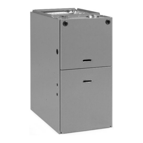
Rheem
Rheem GPT series installation instructions

Payne
Payne PG8JAA042090AAJA Installation and operating instructions
