Steiner MD448 Setup guide

Owner/Operator's Manual
& Illustrated Parts List
Form # 09-254B
ROTARY MOWER
Models MD448, MD460, MD472
Starting Serial No. 1001
CAUTION
Avoid injuries. Read and understand Operator’s manual
before operating tractor or equipment.
It contains instructions for safe operation.

Date of Purchase: Month ________________Day____________________Year _______________
Dealer Name _________________________Phone__________________
Serial Number ________________________
Model Number ________________________
ALWAYS GIVE MODEL AND SERIAL NUMBER WHEN ORDERING SERVICE PARTS
• READ AND UNDERSTAND OPERATORS MANUAL
BEFORE OPERATING OR SERVICING.
• OBEY ALL SAFETY INSTRUCTIONS. FAILURE TO DO SO
MAY RESULT IN INJURY TO YOU OR OTHERS.
• BE SURE MACHINE IS IN SAFE OPERATING CONDITION
BEFORE USE.
• INSPECT MACHINE DAILY. REPLACE ALL WORN OR
DAMAGED PARTS.
• KEEP ALL GUARDS AND SHIELDS IN PLACE.
• CHECK OPERATION OF ALL SAFETY INTERLOCK
SWITCHES DAILY.
• DO NOT OVERRIDE INTERLOCK SYSTEM, IT IS FOR YOUR
PROTECTION.
• DO NOT ALLOW MINORS OR THE INEXPERIENCED TO
OPERATE MACHINE.
• KEEP PEOPLE AND PETS A SAFE DISTANCE AWAY FROM
MACHINE USING POWER DRIVEN ATTACHMENTS.
INJURY COULD RESULT FROM FLYING DEBRIS.
CAUTION
STEINER TURF EQUIPMENT, INC.
289 N. Kurzen Rd., P.O. Box 504
Dalton, Ohio 44618
Telephone: (330) 828-0200
FAX: (330) 828-1008

TABLE OF CONTENTS
INTRODUCTION SECTION 1 page
Description.........................................1-1
Specifications .......................................1-1
SAFETY SECTION 2
General Safety .......................................2-1
Operator Safety ......................................2-1
INSTALLATION INSTRUCTIONS SECTION 3
Installation Instructions ..................................3-1
OPERATION SECTION 4
Operating Precautions...................................4-1
Operating Instructions ...................................4-1
SERVICE SECTION 5
Maintenance Schedule ..................................5-1
Adjustments ........................................5-1
Drive Belt..........................................5-2
PARTS SECTION 6
Parts List and Illustrations Index..............................6-1
ASSEMBLY INSTRUCTIONS SECTION 7
Assembly Instructions ...................................7-1
Warranty .......................................last page
Form 09-254B rev 7/01
8/01 1 - 1. 09-254B
INTRODUCTION section 1
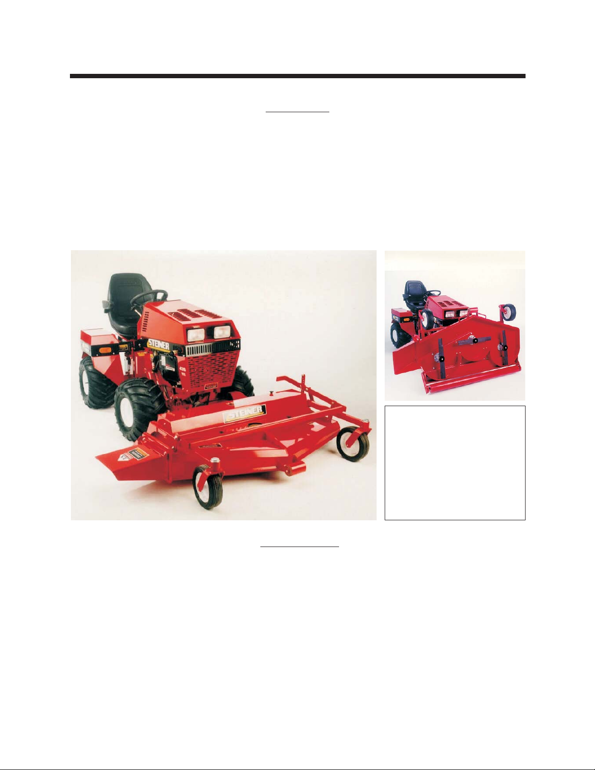
Description
A full-floating rotary mower deck is designed to fit all Steiner power units with the quick hitch front lift.
Three sizes match the power unit to the application. These decks are easy to attach and detach allowing
interchange with the many other front mounted attachments. The side discharge rotary mower provides
even distribution of clippings while the full-floating deck follows the contours of the terrain for an even cut
with cutting height controlled by the front caster wheels and full width rear roller. The deck can be safely
serviced and cleaned while still attached to the tractor. Convenient handles enable the deck to be lifted
vertically over 90 degrees so the blades are fully exposed. Exceptional visibility and maneuvering is
possible with this front mounted design mower.
Specifications
MD448 MD460 MD472
Overall Width with Discharge Chute ____60-1/2" __________73"_____________85"
Overall Height ________________19" ____________19"_____________19"
Overall Length ________________49-1/2" __________48-3/4" __________55"
Cutting Width ________________47" ____________59-3/8" __________72"
Cutting Height ________________1"to4-1/2" ________1"to4-1/2" ________1"to4"
Blades ____________________3-16-1/4"blades ____3-20-1/2"blades _____3-24-3/4" blades
Weight ____________________330lbs. _________360lbs. __________470lbs.
NOTE:
The flip-up deck feature was
added beginning with the
following Serial Numbers;
MD448 - (S/N 1494)
MD460 - (S/N 4728)
MD472 - (S/N 1970)

09-254B 2 - 1 rev 11/02
SAFETY section 2
SIGNAL WORD DEFINITIONS
Indicates an imminently hazardous situation
which, if not avoided, will result in death or
serious injury. This signal word is limited to the
most extreme cases.
Indicates a potentially hazardous situation
which, if not avoided, could result in death or
serious injury.
Indicates a potentially hazardous situation
which, if not avoided, may result in minor or
moderate injury and/or property damage. It may
also be used to alert against unsafe practices.
ATTENTION:
This symbol identifies potential health and
safety hazards. It marks safety precautions. Your
safety and the safety of others is involved.
GENERAL SAFETY
Read and understand the owner's manual, before
attempting to operate this machine.
Operate all controls from the operator's seat, (if so
equipped). NO RIDERS.
Keep all shields in place and safety switches
adjusted properly.
Do not leave equipment unattended. Park on a level
surface, set parking brake, STOP the engine and
remove the key.
Do not allow minors or the inexperienced to operate
this machine.
Keep people and pets a safe distance away from
machines using power driven attachments. Injury
could result from flying debris.
Do not attempt to work on unit or any attachments
with engine running!
Wear all the necessary protective clothing and
personal safety devices to protect your head, eyes,
ears, hands and feet. Operate the machine only in
daylight or in good artificial light.
BE ALERT!

IMPORTANT
Safe Operation Practices for
Mowers
This cutting machine is capable of amputating
hands and feet and throwing objects. Failure to
observe the following safety instructions could
result in serious injury or death.
I General operation
•Read, understand, and follow all instructions in
the manual and on the machine before starting.
•Only allow responsible adults, who are familiar
with the instructions, to operate the machine.
•Clear the area of objects such as rocks, toys ,
wire, etc., which could be picked up and thrown by
the blade.
•Be sure the area is clear of other people before
mowing. Stop the machine if anyone enters the
area.
•Never carry passengers.
•Do not mow in reverse unless absolutely
necessary. Always look down and behind before
and while backing.
•Be aware of the mower discharge direction and do
not point it at anyone. Do not operate the mower
without the discharge chute in place.
•Slow down before turning.
•Never leave a running machine unattended.
Always turn off blades, set parking brake, stop
engine, and remove keys before dismounting.
•Turn off blades when not mowing.
•Stop engine before unclogging discharge chute.
•Mow only in good light, keeping away from holes
and hidden hazards.
•Do not operate the machine while under the
influence of alcohol or drugs.
•Watch for traffic when operating near or crossing
roadways.
•Use extra care when loading or unloading the
machine into a trailer or truck.
•Always wear safety goggles or safety glasses with
side shields when operating mower.
II Slope operation
Slopes are a major factor related to
loss-of-control and tip-over accidents, which can
result in severe injury or death. All slopes
require extra caution. If you feel uneasy on it, do
not mow it.
DO:
•Mow up and down slopes, not across.
•Remove obstacles such as rocks, tree limbs, etc.
•Watch for holes, ruts, or bumps. Uneven terrain
could overturn the machine. Tall grass can hide
obstacles.
•Use slow speed on slopes.
•Follow the manufacturers recommendations for
wheel weights or counterweights to improve
stability.
•Use extra care with grass catchers or other
attachments. These can change the stability of the
machine.
•Keep all movement on the slope slow and gradual.
Do not make sudden changes in speed or
direction.
•Avoid stopping or starting on a slope. If tires lose
traction, disengage the blades and proceed slowly
straight down the slope.
rev 11/02 2 - 2 09-254B
SAFETY section 2

DO NOT:
•Do not turn on slopes unless necessary, and then,
turn slowly and gradually downhill, if possible.
•Do not mow drop-offs, ditches, or embankments.
The mower could suddenly turn over if a wheel is
over the edge of a cliff or ditch, or if an edge caves
in.
•Do not mow on wet grass. Reduced traction could
cause sliding.
•Do not try to stabilize the machine by putting your
foot on the ground.
•Do not use grass catcher on steep slopes.
III Children
Tragic accidents can occur if the operator is not
alert to the presence of children. Children are
often attracted to the machine and the mowing
activity. Never assume that children will remain
where you last saw them.
•Keep children out of the mowing area and under
the watchful eye of another responsible adult.
•Be alert and turn machine off if children enter the
area.
•Before and when backing, look behind and down
for small children.
•Never carry children as passengers, even with the
blades off. They may suddenly fall off and be
seriously injured or interfere with safe machine
operation.
•Never allow children to operate the machine.
•Use extra care when approaching blind corners,
shrubs, trees, or other objects that may obscure
vision.
IV Service
•Use extra care in handling gasoline and other
fuels. They are flammable and the vapors are
explosive.
−Use only an approved container.
−Never remove gas cap or add fuel with engine
running. Allow engine to cool before refueling.
−Do not smoke.
−Never add or drain fuel with machine indoors.
−Never store the machine or fuel container
inside where there is an open flame, such as in
a water heater.
•Never run the machine in a closed area.
•Keep nuts and bolts, especially blade attachment
bolts, tight and keep equipment in good condition.
•Never tamper with safety devices. Check their
proper operation regularly.
•Keep machine free of grass, leaves, and other
debris build-up. Clean up oil or fuel spillage. Allow
machine to cool before storing.
•Stop and inspect the equipment if you strike an
object. Repair, if necessary, before restarting.
•Never make adjustments or repairs with the
engine running.
•Discharge chute components are subject to wear,
damage, and deterioration, which could expose
moving parts or allow objects to be thrown.
Frequently check components and replace with
manufacturer’s recommended parts, when
necessary.
•Mower blades are sharp and can cut. Wrap the
blade(s) or wear gloves, and use extra caution
when servicing them.
•Check brake operation frequently (if equipped).
Adjust and service as required.
09-254B 2 - 3 rev 11/02
SAFETY section 2

rev 1/99 2 - 4 09-254B
SAFETY section 2
MOWER DECK SAFETY DECALS
Location:
On mower deck, front center.
Location:
On mower deck and discharge chute.

09-254B 2 - 5 rev 1/99
SAFETY section 2
DANGER
Location:
On mower deck top front center and both sides.
ROTATING BLADES
LOOK AND LISTEN FOR EVIDENCE OF ROTATION.
DO NOT REMOVE SHIELDS OR ATTEMPT TO SERVICE
UNIT UNTIL ALL COMPONENTS HAVE STOPPED.
Location:
On mower deck top shield.

rev 10/02 3 - 1 09-254B
INSTALLATION section 3
ATTACHING MOWER TO TRACTOR:
-Operate latch control to open hitch latches.
-Drive tractor into position aligning the quick hitch.
-Be sure both latches engage fully and and are placed in the locked position.
-Stop engine! Do not attempt to install drive belt with engine running.
-Release idler assembly to facilitate easy installation of the drive belt.
-Put belt over drive pulleys and engage or adjust idler assembly.
(See Power Unit Operator's Manual for PTO belt tension adjustments.)
-Set mower to desired cutting height.
-Start engine and engage PTO slowly to prevent shock load on mower components.
-Mow with front lift lever in “FLOAT” position only.
REAR WEIGHT REQUIREMENTS
The table of requirements for rear weights is based upon average mowing condi-
tions and operator’s weight of 150 lbs. The recommendations may vary with the weight of
the operator, other accessories, and the mowing conditions. It is the operator’s responsi-
bility to determine the correct amount of weight needed to improve stability. All weights
must be removed when the mower is removed. (See Caution in Power Unit Operator’s
manual.)
Power Unit Model 48” Deck 60” Deck 72” deck
220 / 230 0 weights 0 weights 2 weights
410 2 weights 4 weights This deck is not
recommended.
420/430 2 weights 4 weights 5 weights
425 2 weights 2 weights 4 weights
525 0 weights 0 weights 0 weights
09-254B 4 - 1 rev 11/02
Operating Instructions
-Do not operate mower with discharge chute removed.
- Mow with front lift lever in “FLOAT” position only.
- Engage PTO slowly at low engine r.p.m.
- Mower is designed to operate at full throttle for mowing heavy turf, but 3/4 throttle is adequate for
average conditions. Set mower blade speed with throttle and control ground speed with Forward
- Reverse control.
- Use extreme caution when operating on hills. Mow up and down whenever possible.
- See Section 3 for weight recommendations.
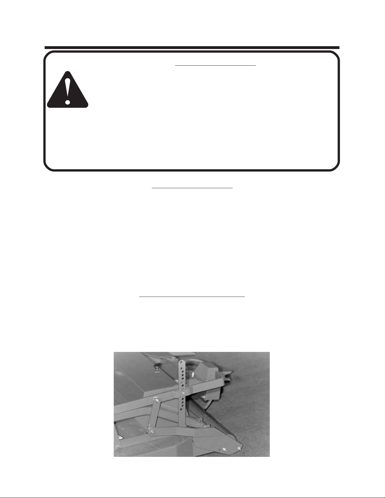
Setting Mower Cutting Height
-Lift mower deck off the ground and shut off tractor engine.
-Remove clevis pin from height adjustment link. See photo 1.
-Raise or lower deck to desired height.
-Replace clevis into height adjustment link.
OPERATION section 4
Operating Precautions
Observe all safety decals.
Keep all shields in place. Do not operate mower with discharge chute removed.
Do not operate mower with other persons in the area. Irregularities in ground
surface can permit foreign material to be propelled from beneath deck to cause
serious injury or death.
Before leaving tractor, stop on a level surface, move Forward - Reverse control to
neutral position, disengage PTO, set parking brake, lower mower deck and stop
engine.
Remove key from ignition if maintenance procedures are to be performed or
tractor is to be left unattended.
Photo 1

rev 8/02 5 - 1 09-254B
SERVICE section 5
MAINTENANCE
Daily maintenance:
·Visual inspection for loose parts and accumulation of grass and dirt.
·Clean accumulation of grass clippings from beneath deck daily for better mowing performance.
·Keep blades sharp. Check the tips of the blades for wear.
25 hour maintenance:
·In addition to daily maintenance, grease roller and all bearings.
·Spindle housings must be kept full of grease. Grease spindles until grease “shows” at the relief hole
under the spindle drive pulley. NOTE: The relief hole is under the spindle hub and is not visible. As
grease enters the spindle housing you can hear the sound of escaping air at the relief hole. Stop
greasing when the sound of escaping air ceases.
·Check drive belt tension. See Drive Belt Installation on page 5-2.
·Check 1/4" cap screws on pulley bushings. Torque should be 95 inch pounds. Tighten these cap screws
in alternating sequence 10-12 times to assure equal torque on all cap screws.
·Check blade bolts. Torque should be 75-85 foot pounds.
Annual Maintenance:
·In addition to daily and 25 hour maintenance, remove the drive belt and check for cracks or wear.
Rotate each spindle to check for roughness which would indicate bearing wear. Remove and sharpen
blades, clean and wash deck prior to storage. The acid in grass clippings causes premature corrosion
and rusting of mower parts.
·Grease all bearings after washing.
ADJUSTMENTS
Sharpening blades
Be careful while sharpening blades that the
corners of the blade do not become rounded at the
tips. This reduces the blades overlap and will cause
skipping. While sharpening, it is essential to ensure
the balance of the blades is maintained to prevent
vibration. Blade bolt torque should be 75-85 foot
pounds. Rotate blades after re-installing to check
for bent or bowed blades and blade alignment.
Blade alignment
When installing sharpened blades or new
blades be sure the mating surfaces are clean and
the retaining washer is not bent. Check for bent
blades by rotating blades until tips are near each
other. (It is easier to do this with main drive belt idler
spring unhooked.)
Leveling mower deck
The front to rear leveling adjustment is pro-
vided by two slots in the linkage which supports the
front of the deck. This allows each side to be ad-
justed independently. Check the blade level with
mower resting on a level floor and the cutting height
set at about 2-1/2" setting. Measure to the tip of the
left blade at the rear, then rotate the blade 180 de-
grees and measure again to the tip of the blade at
the front. The cutting height should be equal or
1/16" lower at the front. Change adjustment in the
left slot as required and measure again until proper
setting is reached. Repeat procedure for blade at
right end of the deck and adjust right slot.

09-254B 5 - 2 rev 8/02
To Remove Belt:
1. Serial Numbers (MD448=1001-1493,
MD460=1001-4727, MD472=1001-1969)
Remove top shield and the bolts which fasten
the hitch arms to the deck brackets. No further
disassembly is necessary.
Serial Numbers (MD448=1494 & Up,
MD460=4728 & Up, MD472=1970 & Up)
Remove the six ¼ x ¾ bolts from the flip-up
braces and remove the pivot stop pin and the
idler spring. Remove the braces.
2. With the idler spring released, move the idler
toward the drive shaft.
3. Slip belt off the outer spindle pulleys.
4. Slip belt off the front center idler and spindle.
5. Remove belt.
To Install Belt:
1. Form loop for drive pulley and idler pulley as
shown. (Photos2&3)
2. Slip loop over drive pulley on left hitch arm.
(Photos2&3)
3. Form a loop around the center spindle pulley
and fixed idler pulley. (Photos2&3)
4. Position belt on the outer spindle pulleys.
(Photos2&3)
5. Serial Numbers (MD448=1001-1493, MD460=
1001-4727, MD472=1001-1969)
Re-install hitch arms and bushings in place .
Serial Numbers (MD448=1494 & Up,
MD460=4728 & Up, MD472=1970 & Up)
Re-install hitch arms and pivot braces. Torque
1/2" attaching bolts to 85 foot pounds. (Photos 2
&3)
6. Hook idler spring in place.
Serial Numbers (MD448=1001-1493, MD460=
1001-4727, MD472=1001-1969)
Choose chain link that stretches spring to an
overall length of 8-9 inches.
Serial Numbers (MD448=1494 & Up,
MD460=4728 & Up, MD472=1970 & Up
Choose chain link which stretches spring
approximately one inch on MD460 or 1-1/2" on
MD448 & MD472.
7. Re-install top shield.
SERVICE section 5
CHANGING MAIN DRIVE BELT
Photo 2 Photo 3

rev 11/02 5 - 3 09-254B
SERVICE section 5
USING THE FLIP-UP OPTION ON THE
MD448, MD460 AND MD472 ROTARY MOWERS
1. Stop on a level surface, set parking brake and shut off the tractor.
2. Lift the deck.
3. Remove the top deck shield and set aside.
4. Standing at the front of the deck, pull the handle on the idler arm so the belt comes loose.
5. Remove the belt from the drive pulley.
6. Remove the presto pin and slide pin from holes.
7. Grasp the handles and lift the deck up and back until you hear a click. This indicates that the latch has
engaged.
8. Lower the deck until the roller touches the ground. This gives stability when working on the deck.
9. Complete your work under the deck.
10. Start the tractor and lift the deck again. Shut off the tractor.
11. Grasp the handles at the front of the deck. Push the deck back slightly and release the catch.
12. Pull the deck forward and down, keeping a firm grip on the handles.
13. Lower the deck to the ground.
14. Replace the pin and clip in the hole above the lift arm.
15. Grasp the idler arm handle again and pull to stretch the spring. Place the belt onto the drive pulley.
16. Make sure the belt is around all pulleys. Release the idler arm.
17. Replace the top shield and secure with the rubber latches.
18. Moving the power unit with the deck in the flipped up position is not recommended. Serious injury and
or damage could result.

09-254B 6 - 1 rev 7/99
PARTS section 6
PARTS INDEX
GROUP FIGURE PAGE
Deck Parts ................
Model MD448 .............Figure 1 .....................6-2
Model MD460 .............Figure 1A.....................6-4
Model MD472 .............Figure 1B.....................6-6
Frame Parts ...............
Model MD448 .............Figure 2 .....................6-8
Model MD460 .............Figure 2A.....................6-10
Model MD472 .............Figure 2B.....................6-12
Hitch and Drive Parts ...........Figure 3 .....................6-14
Spindle Parts ...............Figure 4 .....................6-16
Flip-Up Decks...............Figure 5 .....................6-18
Warranty ............................................last page
ALWAYS GIVE MODEL AND SERIAL NUMBER WHEN ORDERING SERVICE PARTS.
Model MD448 begins with Serial Number 1001
Model MD460 begins with Serial Number 1001
Model MD472 begins with Serial Number 1001
8/01 6 - 2 09-254B
PARTS section 6
Serial No.
1434 & Up
Serial No. 1434 & Up
Serial No. 1434
&Up
Serial No. 1434
&Up
Serial No. 1434
&Up
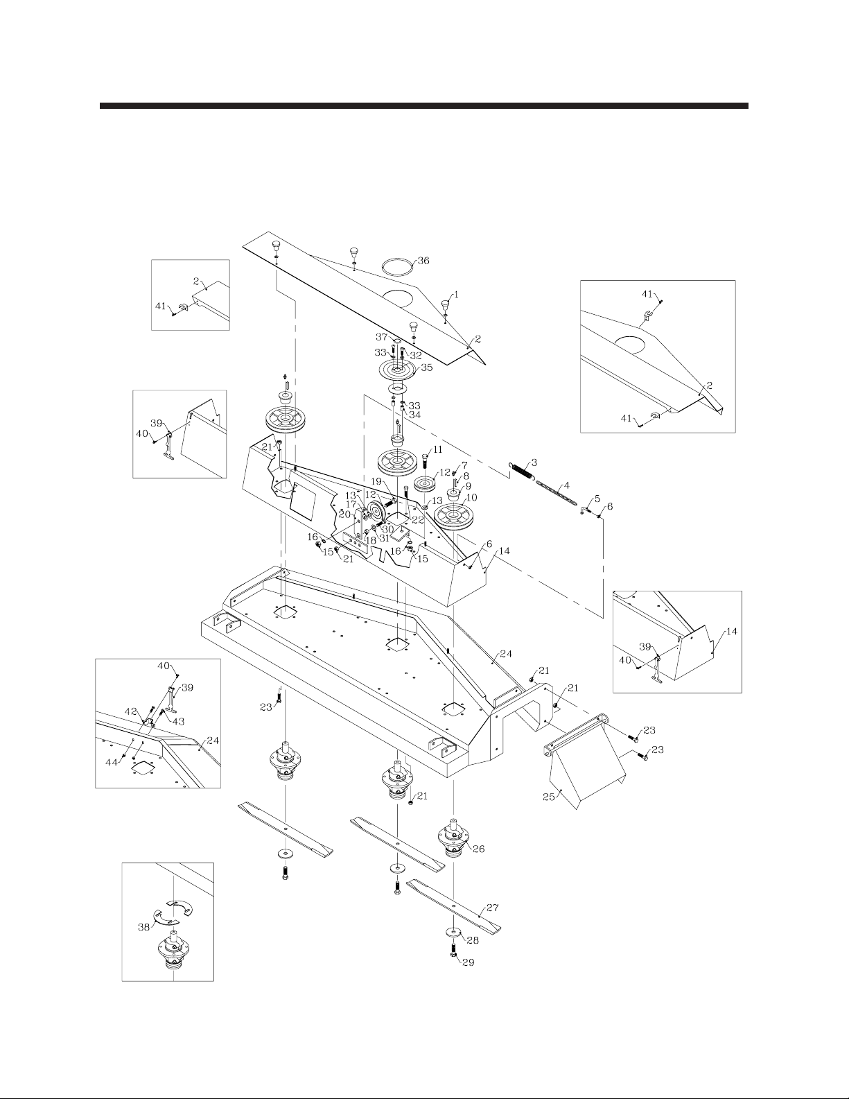
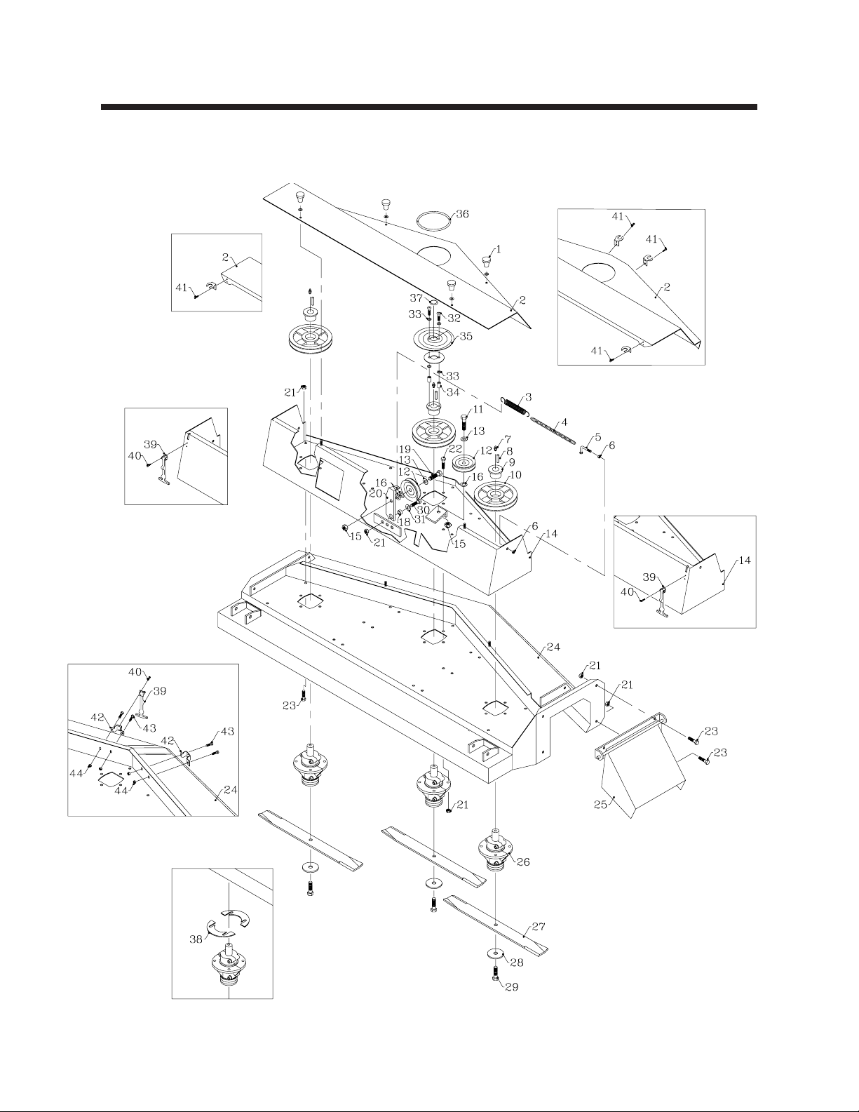
Deck Parts
Model MD448
Figure 1
Optional Repair
Shims

09-254B 6 - 3 rev 3/03
1 47-050 Knob, Ribbed W/ 1/4-20 Threads (Serial No. 1001 - 1433) 4
99-G03 Shakeproof Washer, 5/16" (Serial No. 1001 - 1433) 4
2 60-535 Shield, Top (Serial No. 1001 - 1009) 1
60-567 Shield, Top Deck (Serial No. 1010 - 1433) 1
60-652.17 Shield, Top Deck (Serial No. 1434 - ) 1
3 41-052 Spring, Ext. 0.875 X 6.750 1
4 56-055-11 Chain, Idler Tension (Serial No. 1001 - 1577) 1
5 64-534 Hook, Spring (Serial No. 1001 - 1577) 1
6 99-E20 Flange Nut, 1/4 2
7 29-010 Grease Fitting,1/4 Short 3
8 85-K0408 Key, 1/4 X 1 3
9 83-H16SPL Bushing,HX1"Split Type 3
10 83-BK50H Pulley, 5", H1 Bushing 3
11 90-0812 Bolt, 1/2 X 1-1/2 1
12 83-012 Idler, “V” 1/2" ID X 4-1/2" OD 2
13 99-B12 Washer, 1/4 X 17/32 X 1-1/8 2
14 62-723 Deck, Top (Serial No. 1001 - 1433) 1
62-843 Deck, Top (Serial No. 1434 - 1577) 1
62-872.17 Upper Deck Weldment MD448 (Serial No. 1578 - ) 1
15 92-08 Nut, 1/2 2
16 96-08 Lock Washer, 1/2 2
17 95-08 Flat Washer, 1/2 SAE 1
18 85-B29 Bushing, .406 X .740 X .258 Thick 1
19 90-0814 Bolt, 1/2 X 1-3/4 1
20 40-290 Idler Arm (Serial No. 1001 - 1577) 1
40-329 Idler Arm MD460 & MD448 (Serial No. 1578 - ) 1
21 99-E13 Flange Nut, 3/8 21
22 99-K22 Bolt, Flange 3/8 X 1-1/4 12
23 99-K11 Bolt, Flange 3/8 X 3/4 8
24 62-716 Deck, Mower (Serial No. 1001 - 1433) 1
62-844.17 Deck, Mower (Serial No. 1434 - ) 1
25 60-534.17 Chute, Side Discharge 1
26 87-143 Spindle, Mower 1/2-20 RH Threads 3
27 79-062 Blade, 16-1/4" .700 Air Lift 3
79-064 Blade, 16-1/4" 1-3/8 Air Lift (Optional) 3
28 99-B14 Washer, 1/4 X 1/2 IDX3OD 3
29 91-0810 Bolt, 1/2 X 1-1/4 NF 3
30 90-0608 Bolt, 3/8 X 1 1
31 64-799 Washer, 13/32 x 1-9/32 1
32 99-K38 Bolt, 1/4 X 1-1/4 Button Head (Serial No. 1010 - ) 2
33 95-04 Flat Washer, 1/4 SAE (Serial No. 1010 - ) 4 A/R
34 64-687 Spacer, Rotation Indicator (Serial No. 1010 - ) 2
35 00-137 Decal, Spiral Indicator (Serial No. 1010 - ) 1
60-568 Support, Rotate Indicator (Serial No. 1010 - ) 1
36 56-059-17 Trim-loc, Rubber 17" (Serial No. 1010 - ) 1
37 06-010 Cap Plug,1" (Serial No. 1010 - ) 1
* 00-139 Decal, Warning-Discharge Chute (Serial No. 1010 - ) 2
* 00-140 Decal, ANSI Certification (Serial No. 1010 - ) 1
* 00-138 Decal, Danger-Rotating Blade (Serial No. 1010 - ) 1
* 00-004 Decal, Steiner 1
* 00-092 Decal, Keep Hands & Feet 3
* 00-093 Decal, Warning-Read Owner's 1
* 00-129 Decal, Belt Installation 1
38 64-866 Shim, Spindle 22 Ga.(1 Pair) (Optional) 1
64-867 Shim, Spindle 16 Ga.(1 Pair) (Optional) 1
64-868 Shim, Spindle 12 Ga.(1 Pair) (Optional) 1
39 47-090 Latch, Rubber 3" Long (Serial No. 1434 - ) 3
40 04-008 Pop Rivet, 1/8 X 1/4 SS. (Serial No. 1434 - ) 6
41 04-007 Pop Rivet, 1/8 X 1/8 SS. (Serial No. 1434 - ) 6
42 64-900 Bracket, Top Shield Latch (Serial No. 1434 - ) 1
43 99-K31 Bolt, Flange 1/4 X 1/2 (Serial No. 1434 - ) 2
44 99-E20 Flange Nut, 1/4 (Serial No. 1434 - ) 2
* Not Illustrated
PARTS section 6
Parts List for Model MD448 - Figure 1
Ref. Part No. Description Quantity
rev 3/03 6 - 4 09-254B
PARTS section 6
Serial No.
4189 & Up
Serial No. 4189 & Up
Serial No. 4189
&Up
Serial No. 4189
&Up
Serial No. 4189
&Up
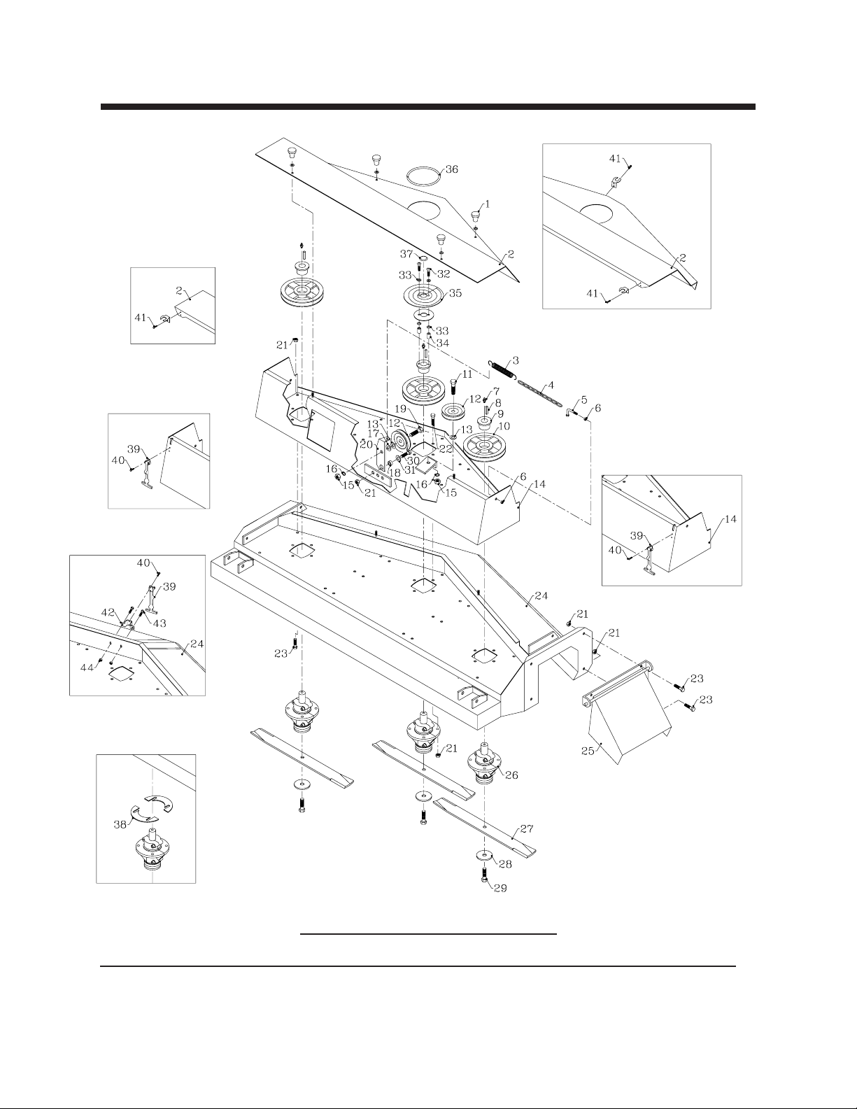
Parts List for Model MD460 - Figure 1A
Ref Part No. Description Quantity
1 47-050 Knob, Ribbed W/ 1/4-20 Threads (Serial No. 1001 - 4188) 4
99-G03 Shakeproof Washer, 5/16" (Serial No. 1001 - 4188) 4
2 60-526 Shield, Top Deck (Serial No. 1001 - 1224) 1
60-544 Shield, Top Deck (Serial No. 1225 - 4188) 1
60-647.17 Shield, Top Deck (Serial No. 4189 - ) 1
Deck Parts
Model MD460
Figure 1A
Optional Repair
Shims

09-254B 6 - 5 rev 3/03
3 41-052 Spring, Ext 0.875 X 6.750 (Serial No. 1001 - 5456) 1
4 56-055-15 Chain, #2 Straight Link (Serial No. 1001 - 5456) 1
5 64-534 Hook, Spring (Serial No. 1001 - 5456) 1
6 99-E20 Flange Nut, 1/4 2
7 29-010 Grease Fitting, 1/4 Short 3
8 85-K0408 Key, 1/4 X 1 3
9 83-H16SPL Bushing,HX1"Split Type 3
10 83-BK72H Sheave, BK72H 3
11 90-0812 Bolt,1/2 X 1-1/2 1
12 83-012 Idler, “V” 1/2" ID X 4-1/2" OD 2
13 99-B12 Washer, 1/4 X 17/32 X 1-1/8 2
14 62-700 Deck, Top (Serial No. 1001 - 1194) 1
62-729 Deck, Top (Serial No. 1195 - 4188) 1
62-835 Deck, Top (Serial No 4189 - 5456) 1
62-868.17 Upper Deck Weldment MD460 (Serial No. 5457 - ) 1
15 92-08 Nut,1/2 2
16 96-08 Lock Washer, 1/2 2
17 95-08 Flat Washer, 1/2 SAE 1
18 85-B29 Bushing, .406 X.740 X.258 Thick 1
19 90-0814 Bolt, 1/2 X 1-3/4 1
20 40-289 Idler Arm (Serial No. 1001 - 1194) 1
40-290 Idler Arm (Serial No. 1195 - 5456) 1
40-329 Idler Arm MD460 & MD448 (Serial No. 5457 - ) 1
21 99-E13 Flange Nut, 3/8 21
22 99-K22 Bolt, Flange 3/8 X 1-1/4 12
23 99-K11 Bolt, Flange 3/8 X 3/4 8
24 62-694 Deck, Main (Serial No. 1001 - 1194) 1
62-727 Deck, Main (Serial No. 1195 - 4188) 1
62-834.17 Deck, Main (Serial No. 4189 - ) 1
25 62-696.17 Chute, Side Discharge 1
26 87-143 Spindle, Mower 1/2-20 RH Threads 3
27 79-050 Blade, 20-1/2" .700 Air Lift 3
79-053 Blade, 20-1/2" 1-3/8 Air Lift (Optional) 3
28 99-B14 Washer, 1/4 X 1/2 IDX3OD 3
29 91-0810 Bolt, 1/2 X 1-1/4 NF 3
30 90-0608 Bolt, 3/8 X 1 1
31 64-799 Washer, 13/32 x 1-9/32 1
32 99-K38 Bolt, 1/4 X 1-1/4 Button Head (Serial No. 1225 - ) 2
33 95-04 Flat Washer, 1/4 SAE (Serial No. 1225 - ) 4 A/R
34 64-687 Spacer, Rotation Indicator (Serial No. 1225 - ) 2
35 00-137 Decal, Spiral Indicator (Serial No. 1225 - ) 1
60-568 Support, Rotate Indicator (Serial No. 1225 - ) 1
36 56-059-17 Trim-loc, Rubber 17" (Serial No. 1225 - ) 1
37 06-010 Cap Plug,1" (Serial No. 1225 - ) 1
* 00-139 Decal, Warning-Discharge Chute (Serial No. 1225 - ) 2
* 00-140 Decal, ANSI Certification (Serial No. 1225 - ) 1
* 00-138 Decal, Danger-Rotating Blade (Serial No. 1225 - ) 1
* 00-004 Decal, Steiner 1
* 00-092 Decal, Keep Hands & Feet 3
* 00-093 Decal, Warning-Read Owner's 1
* 00-129 Decal, Belt Installation 1
38 64-866 Shim, Spindle 22 Ga.(1 Pair) (Optional) 1
64-867 Shim, Spindle 16 Ga.(1 Pair) (Optional) 1
64-868 Shim, Spindle 12 Ga.(1 Pair) (Optional) 1
39 47-090 Latch, Rubber 3" Long (Serial No. 4189 - ) 3
40 04-008 Pop Rivet, 1/8 X 1/4 SS. (Serial No. 4189 - ) 6
41 04-007 Pop Rivet, 1/8 X 1/8 SS. (Serial No. 4189 - ) 6
42 64-900 Bracket, Top Shield Latch (Serial No. 4189 - ) 1
43 99-K31 Bolt, Flange 1/4 X 1/2 (Serial No. 4189 - ) 2
44 99-E20 Flange Nut, 1/4 (Serial No. 4189 - ) 2
* Not Illustrated
PARTS section 6
Parts List for Model MD460 - Figure 1A (Continued)
Ref. Part No. Description Quantity
8/01 6 - 6 09-254B
PARTS section 6
Deck Parts
Model MD472
Figure 1B
Serial No.
1838 & Up
Serial No. 1838 & Up
Serial No. 1838
&Up
Serial No. 1838 & Up
Serial No. 1838
&Up
Optional Repair
Shims
Other manuals for MD448
1
This manual suits for next models
2
Table of contents
Other Steiner Lawn Mower manuals


