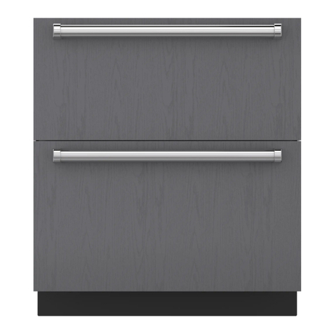
Sub-Zero WOLF ICB User manual

Page 2
SERVICE MANUAL INTRODUCTION
This service manual helps with troubleshooting and diagnosing
malfunctions, completion of repairs, and return of the product to
proper operating condition. Read the complete instructions
contained within before initiating any repairs.
This guide is intended for use by Factory Certified Service. Wolf
Appliance, Inc. recommends that only Factory Certified Service
companies do repairs.
Warning and Caution product safety labels appear throughout
this manual. Product safety labels appear at the beginning of
some sections. Follow the instructions in the product safety
labels to avoid personal injury and/or product damage. The
sample safety labels explain the types of notices that appear in
this manual.
WARNING
States a hazard that may cause serious injury or
death if precautions are not followed.
CAUTION
Indicates minor injury or product damage may occur
if precautions are not followed.
IMPORTANT NOTE: Highlights especially important information.
TIP: Indicates additional, useful information.
Information and images contained herein are copyright of Wolf
Appliance, Inc. Neither this manual nor any information or
images contained herein may be copied or used in whole or in
part without the express written consent of Wolf Appliance, Inc.
©Wolf Appliance, Inc., all rights reserved.
WOLF PRODUCT RATING PLATE INFORMATION
On Vacuum Seal Drawers, the product rating plate is on the side
panel.
Important information for each product is listed on the product
rating plate. Rating plates identify:
▪Model
▪Serial number
▪Electrical information
MODEL DESCRIPTIONS AND SALES ACCESSORIES
For more details on individual model descriptions and a listing
of all compatible sales accessories, see the
Wolf International
Distributor Price List
.
VACUUM SEAL DRAWER MODEL KEY
Model Character Description
ICB International Designation
VS Vacuum Seal Drawer
24 Width (in Inches)
PRODUCT USE AND CARE AND INSTALLATION GUIDES
Product use and care guides, installation guides, and other
product specifications are available in the
Product
Specifications and Manuals Library
.
UNIT WARRANTY
Product warranty is determined by the installation location and
the date of installation.
▪View product warranties at
http://service.subzero.com/
ClaimsAndOrderProcessing/Pages/WarrantyInfo
.
▪Warranties start on the day of product installation.
▪Search for warranty and service information by serial
number, customer last name, and address using Unit
History at
http://service.subzero.com/Tools/UnitHistory
.
ICB Vacuum Seal Drawer
General Information
GENERAL INFORMATION
service.subzero.com
826148 REV. A 01/2019 1

Page 3
THEORY OF OPERATION
This vacuum drawer is solely for vacuuming and sealing food in
suitable vacuum bags and containers. These can then be stored
or processed further (for example, low-temperature cooking or
sous vide cooking).
1The user places the food to be sealed in a vacuum bag, and
then places the bagged food into the vacuum chamber. The
user sets the vacuum level and sealing time using the
buttons on the control panel. With the lid closed, the user
touches to begin the vacuum seal procedure.
2The button turns on the vacuum pump. The vacuum
pump connects to a valve block, consisting of a ventilation
valve (which vents the vacuum chamber to atmosphere) and
a sealing bar valve (which causes the vacuum to move the
vacuum lifting cylinders connected to the sealing bar). Both
of these valves are closed during pump-down, so air is
removed from the vacuum chamber.
3When the pressure sensor on the control board measures
that the specified vacuum level has been reached inside the
vacuum chamber, the control board opens the sealing bar
valve. The pistons in the vacuum lifting cylinders extend
through the vacuum, raising and energizing the sealing bar
to heat-seal the vacuum bag.
4When the specified sealing time has passed, the control
board opens the ventilation valve. Air enters the vacuum
chamber, restoring it to ambient air pressure.
5The return to ambient air pressure causes the vacuum lifting
cylinders to lower. This opens the safety switch, interrupting
the heating of the sealing bar. The user can then open the
lid and remove the food.
1Front panel
2 Control panel
3 Sealing bar
4 Vacuum chamber
5 Vacuum inlet
6 Counterpressure bar
7 Lid
Vacuum Pump, Valve Block, and Vacuum Inlet
The vacuum pump and the valve block (consisting of the
sealing bar valve and ventilation valve) are responsible for
creating and controlling vacuum in the vacuum chamber.
Sealing Bar, Vacuum Lifting Cylinders, and Transformer
During the sealing phase, the pistons in the vacuum lifting
cylinders extend through the vacuum, raising the sealing bar
into contact with the vacuum bag. The upward movement of the
vacuum lifting cylinders closes a safety switch on the underside
of one of the vacuum lifting cylinders, allowing current to flow
from the transformer through the sealing bar (a thermal
protection switch prevents the transformer from overheating).
The sealing bar, pressing the vacuum bag against the
counterpressure bar in the lid, heats up. The heat melts the
plastic of the vacuum bag, creating an air-tight seal.
Control Board
The control board is responsible for controlling the individual
components.
ICB Vacuum Seal Drawer
Theory of Operation
THEORY OF OPERATION
service.subzero.com
826148 REV. A 01/2019 2

Page 4
Control Panel
The control panel communicates the user's settings to the
control board. The control panel also shows the user any error
messages or tips (for example, recommending a
dehumidification cycle). It also contains a reed switch that
senses the magnet in the lid.
Lid and Gasket
The glass lid is laminated and double-glazed. The lid and its
gasket hermetically seal the vacuum chamber. The view into the
vacuum chamber during this process allows the user to
intervene (for example, sealing sooner if bubbles start to form).
ICB Vacuum Seal Drawer
Theory of Operation
THEORY OF OPERATION (continued)
service.subzero.com
826148 REV. A 01/2019 3

Page 5
VACUUM SEAL DRAWER SAFETY
CAUTION
The vacuum chamber and glass lid become distorted
under vacuum. There must be at least a one-
centimeter gap between vessels or screw-top jars
and the appliance lid. Otherwise, the glass can
become damaged and the lid can shatter, causing
personal injury.
CAUTION
The sealing bar in the vacuum chamber gets very
hot. The sealing seam of the vacuum bag also heats
up during the sealing process. Do not touch the hot
sealing bar or other accessible parts, or burns could
result.
CONTROLS
Opening the drawer reveals the control panel, which features
touch controls and LED indicators.
Each control illuminates to indicate that it is active. For vacuum
level, auxiliary vacuum level, and sealing time, three LEDs
above each control indicate the level of vacuum or sealing.
Vacuum and Seal
Vacuum Level: Indicated by one, two, or three illuminated
dashes above .
Seal Level: Indicated by one, two, or three illuminated
dashes above .
CAUTION
Selecting an improper seal level can damage the
sealing bar. Wait at least two minutes between
sealing cycles. All contents must be at or below room
temperature prior to the sealing operation.
1Place food in the vacuum bag.
2Open the lid, and place the bag into the chamber.
3Place the open end of the bag under the bag clip. For
smaller bags, insert the bag support to support the bag
while sealing.
4Touch .
5Touch multiple times to select the desired vacuum level.
6Touch multiple times to select the desired seal level.
7Press down on the lid, and touch to initiate the vacuum
process.
An audible signal indicates the process is complete.
8Open the lid, and remove the food.
Vacuum Only
CAUTION
This process is not intended for canning or making
jam. All contents should be at or below room
temperature.
Jars less than 7.6 cm tall with screw-top lids can be vacuumed
to remove air. Once the vacuum seal is broken, the contents
should be placed in the refrigerator.
1Place the lid on the jar, then lightly tighten the ring and
place in the chamber.
IMPORTANT NOTE: Do not over-tighten the lid. Air must be able
to escape.
2Touch .
3Touch multiple times to select the desired vacuum level.
4Touch multiple times until no LED indicators are
illuminated.
5Touch , then press down on the lid to initiate the vacuum
process.
An audible signal indicates the process is complete.
6Open the lid, and remove the food or jar.
Seal Only
Bags can be sealed without creating a vacuum. The vacuum will
turn on and off briefly during the "seal only" operation to seat
the lid and make sure the sealing bar is in contact with the bag.
TIP: For best results, fill the vacuum seal bags less than half full
when sealing fragile foods.
The original food packaging can be sealed using the "seal only"
function. Adjust the seal level according to the thickness of the
bag. Use seal level 1 for bags thinner than Wolf vacuum seal
bags.
1Place food in the vacuum bag.
ICB Vacuum Seal Drawer
Controls and Operation
CONTROLS AND OPERATION
service.subzero.com
826148 REV. A 01/2019 4
Page 6
2Open the lid, and place the bag into the chamber.
3Place the open end of the bag under the clip. For smaller
bags, insert the bag support to support the bag while
sealing.
4Touch .
5Touch multiple times until no LED indicators are
illuminated.
6Touch multiple times to select the desired sealing level.
Use level 2 for all bags unless otherwise specified for the bag.
7Press down on the lid, and touch to initiate the vacuum
process.
An audible signal indicates the process is complete.
8Open the lid, and remove the food.
Auxiliary Attachment
The included auxiliary attachment allows vacuum sealing of
wine bottles and other rigid containers.
1Place the unit adapter and wine bottle adapter onto
opposite ends of the vacuum hose.
2Place the unit adapter over the vacuum inlet in the vacuum
chamber.
3Place a bottle stopper in the wine bottle.
4Place the bottle adapter over the stopper.
5Touch multiple times to select the desired vacuum level.
Use level 1 for all bottles and rigid containers unless
otherwise specified for the container.
6Touch to start the vacuum process.
TIP: Touching causes the and lights to turn off. To
resume normal operation, select a vacuum setting.
An audible signal indicates the process is complete.
Pump Dehumidification Cycle
If the specified vacuum level is not achieved within the required
time (about two minutes) 10 times, the appliance advises the
user to do a pump dehumidification cycle. The light
illuminates. From this point, the user can run another 10
operating cycles until the appliance quits, forcing the user to
carry out a pump dehumidification cycle.
Without the alarm, the pump dehumidification cycle can only be
started by service personnel using the service menu on the
control panel.
Run a Pump Dehumidification Cycle
Moisture can build up in the vacuum pump oil, which could
damage the unit. Run a pump dehumidification cycle when
appears on the display.
Touch .
The pump cycles for approximately 10 minutes. Once
complete, the unit turns off.
Allow the unit to cool for 1 hour before starting another cycle.
Enter the Service Menu
1With the appliance in standby mode, touch and hold and
at the same time, and hold both buttons for about two
seconds until the appliance beeps.
2While holding and , touch , and hold all three buttons
for about one second until the appliance beeps.
3Release the three buttons within two seconds of the beep.
The Service menu is available, and the following buttons
illuminate:
▪Evacuation time:
▪Sealing time:
▪Start:
▪Stop:
▪Dehumidify:
Exit the Service Menu
Touch to exit the Service menu.
The appliance exits the Service menu, powers down, and
enters standby mode.
ICB Vacuum Seal Drawer
Controls and Operation
SEAL ONLY (continued)
service.subzero.com
826148 REV. A 01/2019 5

Page 7
VACUUM PUMP OIL AND LEAKAGE
CAUTION
The drawer's vacuum pump contains oil that can spill
if the drawer is tilted. Whenever doing any service on
the drawer, make sure that it is level and stable. If the
vacuum pump oil spills, it can contaminate the
vacuum system or the inside of the unit.
GASKET REMOVAL
Remove the Gasket
1Open the lid.
2Starting in the middle of one side, pull the gasket out of the
channel in the lid.
TIP: Do not remove the gasket using a sharp or pointed object.
The gasket could be torn or scratched, affecting vacuum
performance.
3Working around the channel, pull the gasket away from the
glass on all sides until it comes free.
4Remove the gasket from the unit.
GASKET INSTALLATION
Install the Gasket
Install the gasket into the channel in the lid. When fitting the
gasket, make sure its seam is positioned behind the
counterpressure bar on the side where the hinges are (it is
hidden here).
TIP: Soapy water may be used to make it easier to fit the
gasket.
MAGNET REMOVAL
Remove the Magnet
1Open the lid.
2Pull the magnet from the front right corner of the lid. The
magnet is attached with adhesive.
MAGNET INSTALLATION
Install the Magnet
Use the magnet's adhesive backing to attach it to the front
right corner of the lid.
COUNTERPRESSURE BAR REMOVAL
Remove the Counterpressure Bar
1Open the lid.
ICB Vacuum Seal Drawer
Component Removal and Installation
COMPONENT REMOVAL AND INSTALLATION
service.subzero.com
826148 REV. A 01/2019 6

Page 8
2Starting at one corner, pull the counterpressure bar from the
holder.
COUNTERPRESSURE BAR INSTALLATION
Install the Counterpressure Bar
Install the counterpressure bar into the holder.
TIP: Make sure the smooth side faces the lid and the textured
side faces the vacuum chamber.
SEALING BAR ASSEMBLY REMOVAL
WARNING
Turn off the power to the product before starting this
procedure.
Remove the Sealing Bar Assembly
1Open the lid.
2Pull the sealing bar assembly upward to disengage it from
its electrical connections.
3Remove the sealing bar assembly from the vacuum
chamber.
After removing the sealing bar assembly, it is possible to
separate the sealing bar and bag clip from the sealing bar
housing.
SEALING BAR ASSEMBLY INSTALLATION
Install the Sealing Bar Assembly
Position the sealing bar assembly on the locating pins in the
vacuum chamber.
BAG SUPPORT REMOVAL
Remove the Bag Support
1Open the lid.
ICB Vacuum Seal Drawer
Component Removal and Installation
REMOVE THE COUNTERPRESSURE BAR (continued)
service.subzero.com
826148 REV. A 01/2019 7

Page 9
2Pull the bag support from the unit.
BAG SUPPORT INSTALLATION
Install the Bag Support
With the lid open, place the bag support into the unit.
HINGE COVER REMOVAL
Remove the Hinge Cover
1Fully open the lid.
2Loosen the hinge cover by pulling it toward the front of the
unit.
3Remove the hinge cover from the unit.
HINGE COVER INSTALLATION
Install the Hinge Cover
1Place the hinge cover over the hinge.
2Push the hinge cover toward the rear of the unit until it
clicks into place.
LID REMOVAL
To remove the lid, first remove:
1Both
hinge covers
Remove the Lid
1Release the lid from the hinge plates with a left/right
movement.
ICB Vacuum Seal Drawer
Component Removal and Installation
REMOVE THE BAG SUPPORT (continued)
service.subzero.com
826148 REV. A 01/2019 8

Page 10
2Carefully remove the lid from the unit.
LID INSTALLATION
Install the Lid
1Check both hinges are correctly marked and installed (S =
left; D = right).
2Fit the lid into the hinge plates with a left-right movement.
3Position the lid centrally in the fixture.
HINGE SPRING REMOVAL
To remove the hinge spring, first remove:
1Both
hinge covers
2
Lid
Remove the Hinge Spring
Remove the hinge spring from the lid.
HINGE SPRING INSTALLATION
Install the Hinge Spring
Install the hinge spring into the lid.
TIP: Make sure the correct spring is being installed into the
correct side of the lid.
ICB Vacuum Seal Drawer
Component Removal and Installation
REMOVE THE LID (continued)
service.subzero.com
826148 REV. A 01/2019 9

Page 11
FRONT PANEL REMOVAL
Remove the Front Panel
1Pull the vacuum drawer out of the housing, and attach an
adhesive strip to the drawer/housing to prevent it from
sliding.
2Use a 2.5 mm socket to loosen the screws on the left and
right sides of the drawer.
3Use a flat-blade screwdriver in the opening in front of the
drawer slide to pull the front panel and the side panel
slightly apart.
The front panel is no longer attached.
4Push the front panel upward, and remove it from the unit.
FRONT PANEL INSTALLATION
Install the Front Panel
1Attach adhesive strips to the front panel to prevent it from
sliding.
2Push the front panel downward onto the front of the unit.
Mount the front panel from the top down.
3Use a 2.5 mm socket to install the screws on the left and
right sides of the drawer.
CONTROL PANEL REMOVAL
WARNING
Turn off the power to the product before starting this
procedure.
To remove the control panel, first remove:
1
Front panel
Remove the Control Panel
1Use a T-20 Torx bit to remove the front brace screws.
ICB Vacuum Seal Drawer
Component Removal and Installation
service.subzero.com
826148 REV. A 01/2019 10

Page 12
2Remove the front brace from the unit.
3Use a T-10 Torx bit to remove the screws on the underside
of the control panel.
4Disconnect the wire connectors between the control panel
and control board.
CONTROL PANEL INSTALLATION
Install the Control Panel
1Place the control panel into the unit.
TIP: The top side of the lid detection board must face the
magnet on the lid.
2Install the wire connector between the control panel and
control board, routing the cable through the opening in the
drawer cover.
3Use a T-10 Torx bit to install the screws on the underside of
the control panel.
DISCONNECTING THE DRAWER FROM THE SLIDES
CAUTION
The drawer's vacuum pump contains oil that can spill
if the drawer is tilted. Whenever doing any service on
the drawer, make sure that it is level and stable. If the
vacuum pump oil spills, it can contaminate the
vacuum system or the inside of the unit.
To disconnect the drawer from the slides, first remove:
1
Front panel
Disconnect the Drawer from the Slides
1Use a 51/2-mm hex wrench to remove the screws in the
slides (one in the right and one in the left).
2Verify the drawer is loose from the slides by pushing the
slides back under the drawer.
3Pull the drawer out of the housing until it stops on the
slides.
4Lift the drawer slightly so that it does not touch the slides.
ICB Vacuum Seal Drawer
Component Removal and Installation
REMOVE THE CONTROL PANEL (continued)
service.subzero.com
826148 REV. A 01/2019 11

Page 13
5Extend the drawer until the vacuum pump cover is
accessible.
CAUTION
Avoid tipping the drawer. Oil could damage the built-
in filter or leak out.
CONNECTING THE DRAWER TO THE SLIDES
Connect the Drawer to the Slides
1Pull both slides out of the housing as far as they will go.
2Position the drawer on the slides. Make sure that the screw
holes in the slides and extension plates match up.
3Push the drawer together with the slides as far back into the
housing as possible (in the last position).
TIP: The drawer should stand 3 mm proud of the housing.
Adjust the position of the drawer on the slides if necessary.
4Use a 5.5-mm hex driver to install the screws fixing the
drawer to the slides on both the left and right.
CAUTION
Avoid tipping the drawer. Oil could damage the built-
in air filter or leak out.
SIDE PANELS REMOVAL
To remove the side panels, first remove:
1
Front panel
Remove the Side Panels
1Push each side panel from the back to the front until each
stands 0.5 - 1 cm proud of the control panel.
TIP: There are no screws holding the side panels onto the unit.
The side panels use tabs in the front and rear that may be very
tightly fitted.
ICB Vacuum Seal Drawer
Component Removal and Installation
DISCONNECT THE DRAWER FROM THE SLIDES (continued)
service.subzero.com
826148 REV. A 01/2019 12

Page 14
2Pull each side panel away to the side.
3Remove the side panels from the unit.
SIDE PANELS INSTALLATION
Install the Side Panels
1Place each side panel over the appropriate side of the unit.
2Push each side panel from front to back until they are flush
with the control panel.
VACUUM PUMP COVER REMOVAL
CAUTION
The drawer's vacuum pump contains oil that can spill
if the drawer is tilted. Whenever doing any service on
the drawer, make sure that it is level and stable. If the
vacuum pump oil spills, it can contaminate the
vacuum system or the inside of the unit.
To remove the vacuum pump cover, first remove:
1
Front panel
Disconnect the drawer from the slides, and pull it forward
. Then,
remove:
1Both
side panels
Remove the Vacuum Pump Cover
1Use a T-15 Torx bit to remove the screws holding the
vacuum pump cover to the rear of the unit.
2Remove the vacuum pump cover from the unit.
VACUUM PUMP COVER INSTALLATION
Install the Vacuum Pump Cover
1Place the vacuum pump cover onto the unit.
2Use a T-15 Torx bit to install the screws holding the vacuum
pump cover to the rear of the unit.
VACUUM PUMP AIR FILTER REMOVAL
WARNING
Turn off the power to the product before starting this
procedure.
To remove the vacuum pump air filter, first
remove the Vacuum
Seal Drawer from the cabinet
.
Remove the Vacuum Pump Air Filter
1Remove the access cover from the top rear of the unit.
ICB Vacuum Seal Drawer
Component Removal and Installation
REMOVE THE SIDE PANELS (continued)
service.subzero.com
826148 REV. A 01/2019 13

Page 15
2Use a flat-blade screwdriver to remove the vacuum pump
air filter.
VACUUM PUMP AIR FILTER INSTALLATION
Install the Vacuum Pump Air Filter
1Use a flat-blade screwdriver to install the vacuum pump air
filter.
2Install the access cover.
DISCONNECTING THE ENERGY CHAIN FROM THE DRAWER
WARNING
Turn off the power to the product before starting this
procedure.
CAUTION
The drawer's vacuum pump contains oil that can spill
if the drawer is tilted. Whenever doing any service on
the drawer, make sure that it is level and stable. If the
vacuum pump oil spills, it can contaminate the
vacuum system or the inside of the unit.
To disconnect the energy chain from the drawer, first remove:
1
Front panel
Disconnect the drawer from the slides, and pull it forward
. Then,
remove:
1Both
side panels
2
Vacuum pump cover
Disconnect the Energy Chain from the Drawer
1Disconnect the energy chain wire connectors:
▪Mains connection to control board
▪Ground connection
2Remove the cable ties on the bottom of the drawer.
3Feed the mains connection and ground connection through
the hole in the side of the drawer, so that the energy chain is
fully disconnected from the drawer.
CONNECTING THE ENERGY CHAIN TO THE DRAWER
Connect the Energy Chain to the Drawer
1Feed the wire connectors through the drawer.
2Attach the energy chain wire connectors:
▪Mains connection to control board
▪Ground connection to appliance
3Use two cable ties to attach the mains cable to the drawer's
bottom.
REMOVING THE VACUUM SEAL DRAWER FROM THE CABINET
WARNING
Turn off the power to the product before starting this
procedure.
CAUTION
The drawer's vacuum pump contains oil that can spill
if the drawer is tilted. Whenever doing any service on
the drawer, make sure that it is level and stable. If the
vacuum pump oil spills, it can contaminate the
vacuum system or the inside of the unit.
ICB Vacuum Seal Drawer
Component Removal and Installation
REMOVE THE VACUUM PUMP AIR FILTER (continued)
service.subzero.com
826148 REV. A 01/2019 14

Page 16
Remove the Vacuum Seal Drawer from the Housing
1Tape the drawer extension and lid closed.
2Pull the drawer from the housing.
3Place the drawer on an even, stable surface.
Remove the Housing from the Cabinet
1Unplug the power cord from the power socket.
2Loosen the screw connections between the housing's
pilaster strips and the cabinet.
3Remove the housing from the cabinet.
4Unplug the power cord from the rear of the housing.
5Remove the anti-tipping device.
6Put the housing on an even surface (for example, a table).
INSTALLING THE VACUUM SEAL DRAWER INTO THE CABINET
WARNING
Turn off the power to the product before starting this
procedure.
CAUTION
The drawer's vacuum pump contains oil that can spill
if the drawer is tilted. Whenever doing any service on
the drawer, make sure that it is level and stable. If the
vacuum pump oil spills, it can contaminate the
vacuum system or the inside of the unit.
Install the Housing into the Cabinet
1Install the anti-tipping device.
2Plug the power cord into the rear of the housing.
3Insert the housing into the cabinet.
4Install the screws between the housing's pilaster strips and
the cabinet.
5Plug the power cord into the power socket.
Install the Vacuum Seal Drawer into the Housing
1Pull out the slides.
2Place the drawer onto the slides.
3Slide the drawer into the housing until it stops.
ENERGY CHAIN REMOVAL
WARNING
Turn off the power to the product before starting this
procedure.
CAUTION
The drawer's vacuum pump contains oil that can spill
if the drawer is tilted. Whenever doing any service on
the drawer, make sure that it is level and stable. If the
vacuum pump oil spills, it can contaminate the
vacuum system or the inside of the unit.
To remove the energy chain from the drawer housing, first
remove:
1
Front panel
Disconnect the drawer from the slides, and pull it forward
. Then,
remove:
1Both
side panels
2
Vacuum pump cover
Disconnect the energy chain from the drawer
. Then, remove:
1
Drawer from the housing
Remove the Energy Chain from the Drawer Housing
1Use a T-20 Torx bit to remove the screws from around the
mains receptacle.
2Detach the mains receptacle from the connection cover.
ICB Vacuum Seal Drawer
Component Removal and Installation
service.subzero.com
826148 REV. A 01/2019 15

Page 17
3Use a T-20 Torx bit to remove the screws from around the
connection cover.
4Remove the connection cover.
ENERGY CHAIN INSTALLATION
Install the Energy Chain into the Drawer Housing
1Install the mains receptacle into the connection cover.
2Place the connection cover onto the unit.
3Use a T-20 Torx bit to loosely install the screws around
the mains receptacle.
4Use a T-20 Torx bit to install the screws holding the
connection cover to the drawer housing.
5Use a T-20 Torx bit to tighten the screws around the mains
receptacle.
EXTENSION SLIDES REMOVAL
WARNING
Turn off the power to the product before starting this
procedure.
CAUTION
The drawer's vacuum pump contains oil that can spill
if the drawer is tilted. Whenever doing any service on
the drawer, make sure that it is level and stable. If the
vacuum pump oil spills, it can contaminate the
vacuum system or the inside of the unit.
To remove the extension slides from inside the drawer housing,
first remove:
1
Front panel
Disconnect the drawer from the slides, and pull it forward
. Then,
remove:
1Both
side panels
2
Vacuum pump cover
Disconnect the energy chain from the drawer
. Then, remove:
1
Drawer from the housing
2
Housing from the cabinet
Remove the Extension Slides
1Use a T-20 Torx bit to remove the screws on the exterior of
the appliance housing.
2Remove the extension slides.
ICB Vacuum Seal Drawer
Component Removal and Installation
REMOVE THE ENERGY CHAIN FROM THE DRAWER HOUSING (continued)
service.subzero.com
826148 REV. A 01/2019 16

Page 18
EXTENSION SLIDES INSTALLATION
Install the Extension Slides
1Place the extension slides over the sides of the unit.
2Use a T-20 Torx bit to install the screws on the exterior of
the drawer housing.
CAPACITOR REMOVAL
WARNING
Turn off the power to the product before starting this
procedure.
CAUTION
The drawer's vacuum pump contains oil that can spill
if the drawer is tilted. Whenever doing any service on
the drawer, make sure that it is level and stable. If the
vacuum pump oil spills, it can contaminate the
vacuum system or the inside of the unit.
To remove the capacitor, first remove:
1
Front panel
Disconnect the drawer from the slides, and pull it forward
. Then,
remove:
1Both
side panels
2
Vacuum pump cover
Disconnect the energy chain from the drawer
. Then, remove:
1
Drawer from the housing
Remove the Capacitor
1Use a 13-mm combination wrench to remove the nut on the
outside right of the drawer's bottom.
2Remove the capacitor from the unit.
3Mark the capacitor wire connectors.
4Disconnect the wire connectors between the capacitor and
vacuum pump.
CAUTION
High voltage may be present at the capacitor's
terminals. Touching the terminals may result in severe
electric shock!
CAPACITOR INSTALLATION
Install the Capacitor
1Insert the capacitor into the unit.
2Connect the wire connectors between the capacitor and
vacuum pump.
3Use a 13-mm combination wrench to install the nuts on the
outside right of the drawer's bottom.
VACUUM INLET REMOVAL
WARNING
Turn off the power to the product before starting this
procedure.
CAUTION
The drawer's vacuum pump contains oil that can spill
if the drawer is tilted. Whenever doing any service on
the drawer, make sure that it is level and stable. If the
vacuum pump oil spills, it can contaminate the
vacuum system or the inside of the unit.
To remove the vacuum inlet, first remove:
1
Front panel
Disconnect the drawer from the slides, and pull it forward
. Then,
remove:
ICB Vacuum Seal Drawer
Component Removal and Installation
service.subzero.com
826148 REV. A 01/2019 17

Page 19
1Both
side panels
2
Vacuum pump cover
Disconnect the energy chain from the drawer
. Then, remove:
1
Drawer from the housing
Remove the Vacuum Inlet
1Open the lid.
2Twist the vacuum inlet counterclockwise to remove it from
the inside of the vacuum chamber.
TIP: When the vacuum inlet comes free, the threaded valve
block connection may fall through into the bottom of the unit.
The valve block's inward-facing O-ring (on the opposite side of
the vacuum chamber from the vacuum inlet) may also fall into
the bottom of the unit. If only replacing the vacuum inlet,
carefully hold the threaded valve block connection in place.
VACUUM INLET INSTALLATION
Install the Vacuum Inlet
Screw the vacuum inlet onto the threaded valve block
connection in the tray.
TIP: Pull the threaded connection tight against the tray so that
the inner O-ring connects properly.
DISCONNECTING AND REMOVING THE VACUUM CHAMBER
WARNING
Turn off the power to the product before starting this
procedure.
CAUTION
The drawer's vacuum pump contains oil that can spill
if the drawer is tilted. Whenever doing any service on
the drawer, make sure that it is level and stable. If the
vacuum pump oil spills, it can contaminate the
vacuum system or the inside of the unit.
To disconnect and remove the vacuum chamber, first remove:
1
Front panel
Disconnect the drawer from the slides, and pull it forward
. Then,
remove:
1Both
side panels
2
Vacuum pump cover
Disconnect the energy chain from the drawer
. Then, remove:
1
Drawer from the housing
2
Vacuum inlet
Disconnect and Remove the Vacuum Chamber
1Use a T-20 Torx bit to loosen the eight screws on the top
side of the vacuum chamber (four on the left and four on the
right).
CAUTION
Do not remove the two screws from the hinge plate
on the left and right!
2Carefully lift the vacuum chamber away from the drawer.
Make sure no cables or tubes are crushed or damaged.
3Mark and disconnect all electrical and vacuum connections.
4Remove the vacuum chamber from the unit.
INSTALLING AND CONNECTING THE VACUUM CHAMBER
Install and Connect the Vacuum Chamber
1Connect all electrical and vacuum connections.
ICB Vacuum Seal Drawer
Component Removal and Installation
service.subzero.com
826148 REV. A 01/2019 18

Page 20
2Rotate the chamber down into position over the drawer
housing.
3Use a T-20 Torx bit to install the eight screws on the top
side of the chamber (four on the left and four on the right).
MOVING THE VACUUM CHAMBER FOR COMPONENT ACCESS
WARNING
Turn off the power to the product before starting this
procedure.
CAUTION
The drawer's vacuum pump contains oil that can spill
if the drawer is tilted. Whenever doing any service on
the drawer, make sure that it is level and stable. If the
vacuum pump oil spills, it can contaminate the
vacuum system or the inside of the unit.
To move the vacuum chamber for access to the components
behind it, first remove:
1
Front panel
Disconnect the drawer from the slides, and pull it forward
. Then,
remove:
1Both
side panels
2
Vacuum pump cover
Disconnect the energy chain from the drawer
. Then, remove:
1
Drawer from the housing
2
Vacuum inlet
Move the Vacuum Chamber for Component Access
1Use tape to seal the lid closed.
2Use a T-20 Torx bit to remove the screws that attach the
vacuum chamber to the underside on the left and right.
3Lift the vacuum chamber carefully off the lower section, and
rest it on the housing at an angle to allow access to the
components behind the tray. Make sure no cables or tubes
are crushed or damaged. Take particular care that the
transformer cable, the cable on the vacuum lifting cylinders
for the safety switch, and the suction tube with non-return
valve on the vacuum pump are not twisted, crushed, or
damaged.
REPOSITIONING A MOVED VACUUM CHAMBER
Move the Vacuum Chamber Back into Position
1Set the vacuum chamber carefully onto the lower section.
Make sure no cables or tubes are crushed or damaged.
Take particular care that the transformer cable, the cable on
the vacuum lifting cylinders for the safety switch, and the
suction tube with non-return valve on the vacuum pump are
not twisted, crushed, or damaged.
2Use a T-20 Torx bit to install the screws that attach the
vacuum chamber to the underside on the left and right.
VACUUM PUMP REMOVAL
WARNING
Turn off the power to the product before starting this
procedure.
CAUTION
The drawer's vacuum pump contains oil that can spill
if the drawer is tilted. Whenever doing any service on
the drawer, make sure that it is level and stable. If the
vacuum pump oil spills, it can contaminate the
vacuum system or the inside of the unit.
To remove the vacuum pump, first remove:
1
Front panel
ICB Vacuum Seal Drawer
Component Removal and Installation
INSTALL AND CONNECT THE VACUUM CHAMBER (continued)
service.subzero.com
826148 REV. A 01/2019 19
Table of contents
Other Sub-Zero LCD Drawer manuals
Popular LCD Drawer manuals by other brands

Austin Hughes Electronics
Austin Hughes Electronics Cyberview RKP-1015 user manual

Little Shed Creations
Little Shed Creations Desk Tidy Assembly instructions

NetView
NetView NVP215-S801 user manual

Acnodes
Acnodes M3916 user manual

Acnodes
Acnodes RK 1000B installation guide

Bosch
Bosch HMD8053UC use and care manual