SVS 12HSE LIFT User manual

SVS 12HSE LIFT
INSTALLATION INSTRUCTIONS
(220V)
SVS, INC. Lifting Your Image
2513 Jenks Ave
Panama City, FL 32405
www.svslifts.com
Tel 850-522-4747
Fax 850-522-4739
International Sales
Tel 001-720-283-6410
Fax 001-720-283-6424
SVS 12HSE Lift Installation Instructions Page 1 of 16

SVS 12HSE LIFT
INSTALLATION INSTRUCTIONS
SECTIONS: Page
1. General escription.................................................................................................................................3
2. Features & Specifications........................................................................................................................3
3. Lift Warranty...........................................................................................................................................4
4. Preliminary Installation Checks.............................................................................................................5
5. Considerations for Lift Placement..........................................................................................................6
6. Lift Supporting Structure........................................................................................................................6
7. Lift Installation.........................................................................................................................................8
8. Electrical Connections.............................................................................................................................10
a. How to Use the Wall Plate Controller..........................................................................................10
b. Connecting to a Touch Screen Controller (External Controller)..............................................11
9. Accessory Installation..............................................................................................................................11
10. Cable Management..................................................................................................................................12
11. Setting the Show Position........................................................................................................................13
12. Maintenance and Adjustments...............................................................................................................14
13. Troubleshooting........................................................................................................................................15
SVS 12HSE Lift Installation Instructions Page 2 of 16

SVS 12HSE LIFT
1. General escription:
The SVS 12HSE Series Lift support large projectors (up to 32.5"
[82.5cm] wide) that require additional size and weight
accommodations. It features the “longest” lowering distances from
24-feet 9-inches (7.59m) to 33-feet 8-inches (10.3m). This model is
supplied with an Accessory #13 Removable Welded Steel Platform
to support projector (non-inverted) and Dual Accessory #7 Cable
Retractors. This model has been designed with safety in mind, it
features redundant limit switches, a patented drum lock system and
a grooved cable drum for level and accurate image tracking.
Figure 1. shows the SVS 12HSE Series Projector Lift with projector and
Accessory #1 Removable Platform (projector not included).
2. Features & Specifications
Lowering istances:
•SVS 12HSE-24 24' 9” (7.59m)
•SVS 12HSE-29 29' 3” (8.9m)
•SVS 12HSE-33 33' 8” 910.3m)
(all SVS 12HSE Lifts include ual Cable Retractors)
Lift Height in Closed Position (*):
•SVS 12HSE-24 27.5” (72.4cm)
•SVS 12HSE-29 30.5” (80.0cm)
•SVS 12HSE-33 33.5” (87.6cm)
(*accessories/support structure additional)
Lift Positions:
•Storage – Projector can be aesthetically stored above the ceiling when not in use.
•Show – Projector automatically positioned for show/operation.
•Service – Projector easily lowered for service.
Lift Capacity Up to 700 lbs [317.5 Kg] Lift Weight: From 410 lbs (186kg)
Maximum Projector Width: 32.5” (82.5cm)
Voltage
Material
•110V/60Hz @ 1.5Amps
•Steel/Aluminum/Nylon
•220V/50Hz@ .75Amps
•Steel/Aluminum/Nylon
Low Voltage Control
•Wall Plate Controller supplied with lift
•24VAC Contact Closure Control (latch to move lift)
•Connects to lift using supplied 12-pin connector and 75-feet of cable (22 AWG/9 Conductor)
Precision Grooved rum – Provides accurate and level tracking for consistent screen image.
Patented Fail Safe rum Lock System – Insures safety in the event of mechanical failure. 100% safety
record for 20 years of manufacturing.
Quiet and Strong Motor – Extra quiet for meeting and presentations or simply for home use.
Redundant Limit Switches (up & down) – For secure and safe motor shutdown.
Cable Management System – Keeps cables out of the way during lift operation.
Operating Temperatures: 32°F to 104°F [0°C to 40°C] Maximum Humidity 85%
SVS 12HSE Lift Installation Instructions Page 3 of 16
Figure 1. SVS 12HSE Projector Lift

3. SVS 12HSE LIFT WARRANTY
SVS, Inc. 's limited warranty only covers failures due to defects in materials or workmanship that occur
during normal use. This limited warranty OES NOT cover failures resulting from accident, misuse,
abuse, neglect, mishandling, misapplication, faulty or improper installation and set-up adjustments,
improper maintenance or alteration. Specific product warranties are as follows:
A 5-year parts and 90-day factory labor warranty applies to the following SVS products:
•All scissors style lifts
•Accessory #11 Extra Show Position
•Accessory #14 Floor Access Motor Control
•Accessory #15 12-Volt Trigger
A 1-year parts and 90-day factory labor warranty applies to the following SVS products:
•All Lift Motors
•Accessory #1 Ceiling Closure
•FP1 Closure Panel
•Accessory #2 Plenum Shroud
•Accessory #9 Projector Mount
•Accessory #10 Dual Stack Projector Mount
•Accessory #13 Platforms
A Return Material Authorization (RMA) number must be received from SVS prior to the return of any
product. Products returned to SVS must be shipped adequately insured with freight prepaid and the
RMA number clearly noted on the shipping label and crate. Items received freight collect or without
RMA numbers clearly noted will be refused. Lift model, serial number, and proof of original purchase
date may be required before warranty performance is rendered.
SVS 12HSE Lift Installation Instructions Page 4 of 16

IMPORTANT: PLEASE REA THROUGH ALL INSTRUCTIONS
BEFORE BEGINNING YOUR INSTALLATION.
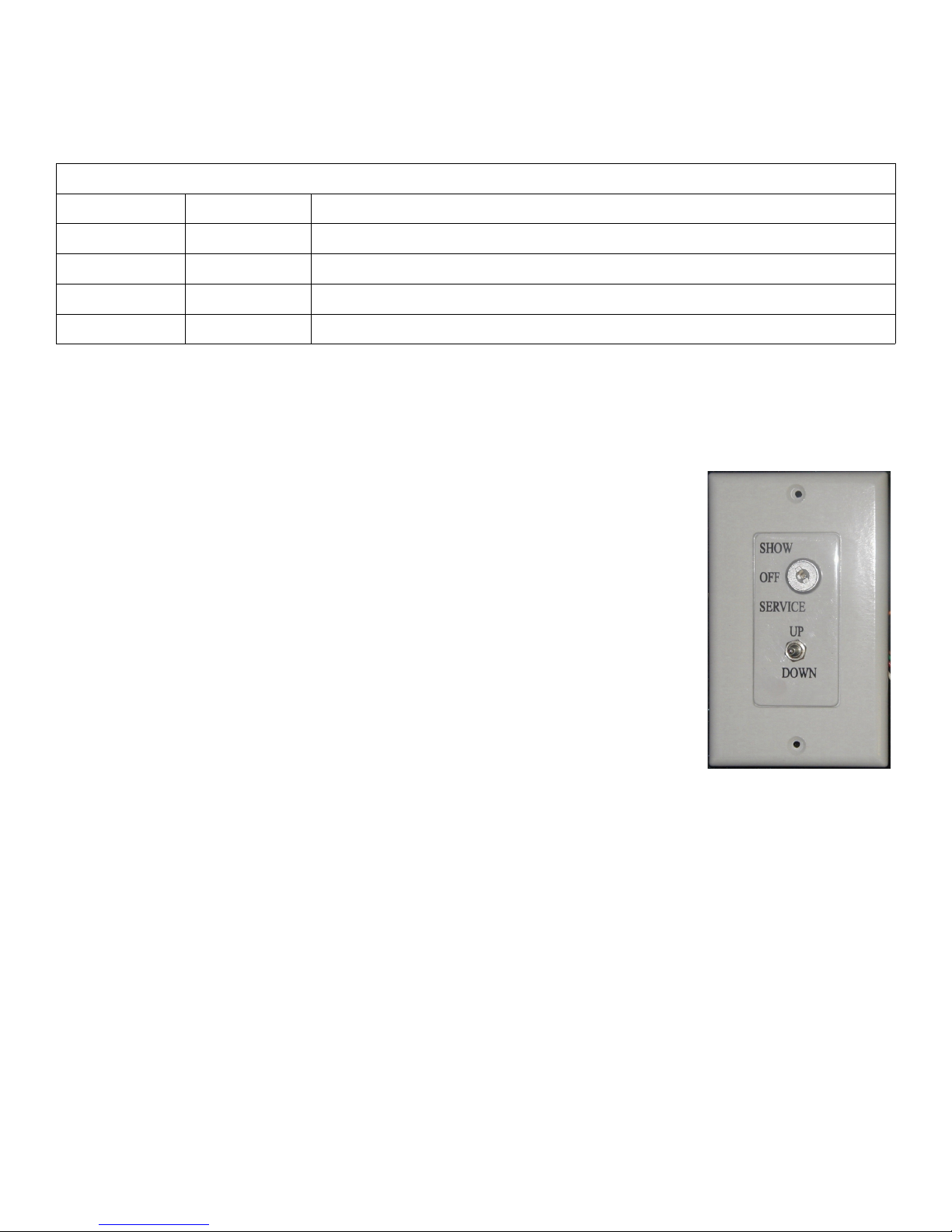
This Lift is designed to be used with a Wall Plate Controller, either automatically or manually controlled
and will function without any special training in the “Show” mode. The Wall Plate Controller features a
key switch which can be placed in the “Show” or “Auto” positions for normal operation. The “Off”
position disables the Lift. The “Service” position must be used only by trained technical personnel when
the Lift is lowered to floor level for service/access.
Note: The “Auto” position on the Wall Plate Controller is for Accessory #15 12-Volt Trigger only
WARNING
To prevent personal injury and property damage when servicing any part of the Lift drive system
(electric motor/brake, drive chain/sprockets, steel lift cables, and/or drum lock assembly) the projector
must be removed and the Lift's lower frame supported by straps, chain, or cable to prevent it from
lowering unexpectedly while the drive system is being serviced.
IMPORTANT
Please read all Accessory Installation Instructions before beginning your installation. If an Accessory #2
Plenum Shroud is to be installed with the Lift. Please read the Accessory Installation Instructions before
beginning your installation. The Lift support structure will need to allow enough space to install the
mounting hardware for the Plenum Shroud.
TO AVOI CABLE SPILLS
•o not push the lift bottom frame upwards once the Lift has been installed.
•Make sure that there are no obstructions in the Lift's path. If the bottom frame is lowered onto an
obstruction the cable will slack and spill over the cable drum.
4. PRELIMINARY INSTALLATION CHECKS
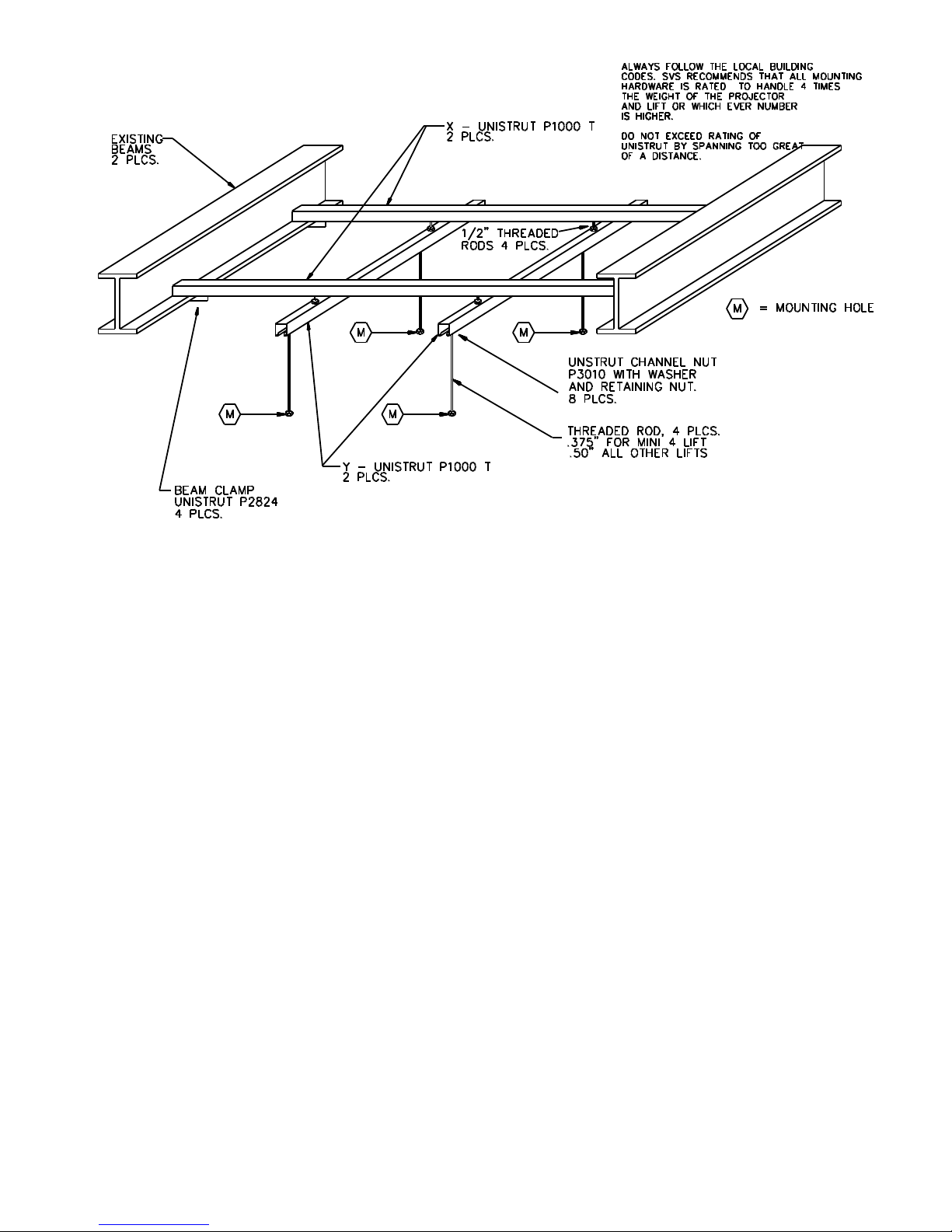
•SVS recommends that the Lift support structure holds at least four (4) times the weight of the Lift and
projector combined. Always follow your local building codes.
•Required space for the Lift, Projector, and accessories should be considered prior to installation. Check
for obstructions that may prevent the Lift or accessories from being installed or operated.
•Plan for necessary Lift low voltage control cabling, projector audio/video/control cabling, and power
connections.
•Do not install the projector on the Lift until the Lift, hardware, and any accessories have been properly
installed and are operational.
•This Lift has been adjusted with cables tightly packed on the cable drum and leveled for precise tracking
prior to being shipped from the factory. o not remove the lift's shipping blocks until instructed to
do so in Section 7. SVS scissor lifts are shipped in a slightly open position to eliminate stress on the
limit switches and to maintain a tight cable pack on the cable drum. If physical height measurements are
taken before the blocks are removed from the Lift, they may not accurately reflect the height of the
closed Lift.
•All weight attached to the Lift must be centered between the lift's cables. The balance point of the
projector should be placed in line with the Lift cables (+/- 1-inch). If this is not possible you may need to
counter weight the Lift to keep the Lift level.
•As a reminder, clear all persons and obstructions from the Lift's path during its operation. Keep fingers
and other objects away from the scissors and other moving parts. Technical personnel should always be
present whenever the Lift is in the Service mode.
SVS 12HSE Lift Installation Instructions Page 5 of 16

5. CONSI ERATION FOR LIFT PLACEMENT
•Before beginning the installation, check the dimensions of the lift against the available space above the
ceiling. Be sure to include the projector lens and any accessories which may add to the overall
dimensions
•Preliminary measurements should also be made to layout the orientation of the projector and lift to the
screen. Consider if the lens is offset from the center of the projector and thus the center of the Lift.
6. LIFT SUPPORTING STRUCTURE
The SVS 12HSE Lift should be mounted
from six 1/2” rods. The mounting hole
locations are marked with a <M> in
Figure 3. The thread rods must be
supported by a rigid structure. If the
threaded rods exceed more than 2-feet
(0.6 M) from the support structure to the
lift's top mounting holes cross bracing
should be installed between the support
rods. Figure 4 shows the cross bracing
and the correct height for mounting the
lift above the false ceiling.
Note: SVS 12HSE Lift imensions
may vary with projectors. Please
verify the Lift dimensions on the Lift
imension drawing included in the
Lift Installation package.
SVS 12HSE Lift Installation Instructions Page 6 of 16
Figure 2. SVS 12HSE Front & Side Views
Figure 3. SVS 12HSE Top View

If the ceiling clearance allows, an “X-Y” or a cross-supporting structure is strongly suggested as shown in
Figure 6 Recommended Lift Support Structure for Flat Ceilings. This allows for front-to-back and side-to-side
adjustments of the Lift for alignment to the screen.
SVS 12HSE Lift Installation Instructions Page 7 of 16
Figure 4. Cross Bracing & Correct Height
Figure 5a. Recommended Lift Support Structure for Flat Ceilings

Important
When attaching the Lift to a flat concrete ceiling, SVS suggest two (2) pieces of P1000T Unistrut (or
equivalent) approx. 10-feet (3.04 m) long, to be installed on the ceiling first. Proper spacing between the two
pieces will be based on the distance between the four (4) mounting holes of the Lift as shown in Figure 4.
You should use at least four (4) 1/2” bolts and anchors evenly spaced on each piece of Unistrut to distribute the
weight of the supporting structure. Attach the two lower pieces of Unistrut to the upper two pieces of Unistrut
using 1/2” threaded rods to the Unistrut, using Unistrut P3010 1/2” channel nuts in the channel, along with a
locking washer and nut below the channel to lock into place.
IMPORTANT
If you are installing an Accessory #2 Plenum Shroud with the Lift, please read the Accessory Installation
Instructions before beginning your installation. The Lift support structure will need to allow enough
space for the Plenum Shroud mounting hardware.
7. LIFT INSTALLATION
a. Preparation:
1. The Lift is shipped in a wooden crate.
2. Do not remove the Lift from the crate until you are ready to install it.
3. The Installation Instructions, Wall Plate Controller with control cable, and projector mounting hardware
are located in a cardboard box inside the crate.
4. Unbolt the Lift from the bottom of the crate to remove the lift from the crate.
b. Installing the Lift in the Ceiling
SVS 12HSE Lift Installation Instructions Page 8 of 16

1. Raise the Lift into the ceiling and line up the six (6)
mounting holes in the Lift's top frame with the 1/2”
threaded rods of the supporting structure. Make sure that
there is a top nut and a flat washer on each threaded rod
before the Lift is mounted. See Figure 6. (Plenum Shrouds
require additional hardware installed on the threaded rods
before the Lift.)
2. Once the Lift's top frame has been inserted, add a hexnut to
each threaded rod below the Lift frame. Always leave the
top nut loose to allow adjustments until the Lift is leveled.
3. Level the Lift's top frame side-to-side and front-to-back
using the lower hexnuts on the threaded rods.
4. Once the Lift is leveled, secure the Lift to the threaded rods by tightening the upper hexnuts. Do not
over tighten the fasteners as it could distort the Lifts top frame.
5. Plug the 12-pin connector of the Wall Plate Controller into the 12-pin socket on the Lift's gray electrical
box mounted on the Lifts top frame. The Wall Plate Controller includes 75-feet of cable and is shipped
with the Lift. It is located in the cardboard box attached to the lid of the Lift's shipping crate.
6. Once the Lift is properly installed in the ceiling and leveled, you can remove the shipping blocks.
Remove the blocks by removing the screws and tie-raps holding them in place.
Leveling the Projector
•If you can not level the projector using the projector's leveling adjustments, you can adjust the level of
the lift.
•Level corrections are made with the projector mounted after confirming that the cable is packed tightly
and is straight on the Cable Drum.
•It is best to lower the lift to the Service position and then completely up before leveling the projector.
•Level adjustments should be made with the projector in the Show position.
•Position a level across the front of the projector. Fine adjustments are done by adjusting the nuts on the
bottom of the cable eye bolts. Raise and lower the Lift until satisfactory level is achieved.
•After adjustments are made tighten the eye bolt nuts.
TO AVOI CABLE SPILLS
•o not push the lift bottom frame upwards once the Lift has been installed.
•Make sure that there are no obstructions in the Lifts path. If the bottom frame is lowered onto an
obstruction the cable will slack and spill over the cable drum. If the cable spills over the cable
drum and the Lift is not stopped the cable will back-wind onto the cable drum causing severe
damage to the Lift and accessories.
8. ELECTRICAL CONNECTIONS
SVS 12HSE Lift Installation Instructions Page 9 of 16

Electrical connections should be made at this time. The SVS 12HSE requires 220V/50Hz at 1.2 Amps and is
supplied with a six foot power cord. The SVS 7 Lift is controlled with a 24VAC Low Voltage Controller called
the Wall Plate Controller. This controller can easily be connected to external controllers like Crestron, AMX,
Extron, etc. The Wall Plate Controller is supplied with 75-feet of cable (22 AWG, 9 conductor).
Wall Plate Controller Information
Wire Color Connector Pin Function
Black 3 Down to Show Position when 24VAC connected from Pin 1
Green 4 Down to Service Position when 24VAC connected from Pin 1
Red 2 Up when 24VAC connected from Pin 1
White 1 24 VAC Out (Common) (can be measured between Pin 1 and Pin 7)
1. Make sure that the area below the Lift is clear and that all cable are clear of the Lift.
2. Apply power to the Lift by plugging it into an AC Outlet.
a. How to use the Wall Plate Controller
1. To lower the Lift to the Show position, turn the key switch to the Show
position and press the toggle switch down. The lift will lower as long as you
hold the toggle switch down, the lift will stop when the rear scissor roller
compresses the Show Position microswitch.
2. To lower the Lift to the Service position, turn the key switch to the Service
position and press the toggle switch down. The Lift will lower as long as
you hold the toggle switch down, the Lift will stop when the rear scissor
roller compresses the own Limit microswitch. The Service position
bypasses the Show Position microswitch.
3. To raise the lift press the toggle switch up. The Lift will rise until the Up
Limit microswitches are compressed. The Lift will rise as long as you hold
the toggle switch up. The Lift can be raised with the key switch in either the
Show or Service positions.
4. The Off position on the key switch disables the Lift.
5. The Power light only comes on when the Lift is raising or lowering (Lift
motor turning), not when power is applied to the Lift.
Important The toggles switch on the Wall Plate Controller must be pressed to raise or lower the Lift, releasing
the toggle switch stops the Lift. This is designed as a safety feature. The key switch is an extra precaution, when
the key is removed, the Lift is secure.
SVS 12HSE Lift Installation Instructions Page 10 of 16

b. Connecting a Touch Screen Controller (External Controller)
The simplest external controller connections are to use the White wire (pin 1) as the common and the Black (pin
3) for down to Show position and the Red wire (pin 2) for up. For this and other wiring options please refer to
the external controller wiring diagrams in the Appendix. Also
1. Program a release of relays to stop the Lift on up and down positions
2. Program a time out after the normal runtime, 2 seconds max. (SVS Lifts raise/lower at 1-inch/second.)
3. Program an exclusive lockout on up and down so that both cannot be activated at the same time. (Note
SVS Lifts have a lockout function that disables the Lift when it receives a up and down command at the
same time. Removing one of the two commands releases the lockout condition.)
4. Hold relays on to raise/lower the Lift.
5. Never leave voltage on the up and down. Always program a release after the travel time has been
achieved.
If you have any questions please contact SVS for proper wiring.
9. ACCESSORY INSTALLATION
Please refer to the accessory installation instructions located in the accessory shipping crates for specific
instructions for each accessory. The Accessory #2 Plenum Shroud requires that hardware be added to the
threaded rods supporting the Lift before the Lift is installed. The Accessory #1 Ceiling Closure and FP1 Closure
Panel attach the ceiling closure support brackets on the platform of the Lift using supplied threaded rods.
11. CABLE MANAGEMENT
SVS 12HSE Lift Installation Instructions Page 11 of 16
VIEW F RO M BACK
RP2
S HOW-OFF-S E RV ICE
DOWN
WHT
WHT
WHT
ORN
BLK
UP
RED
GRN
BL K
G RN
1
2
C
( SERVICE)
( SHO W)
( 2 4 va c)
1 11 12
789
654
1 2 3

Cable Management is used to keep projectors cables away
from the scissors during Lift operation. Do not attach the
projector cables to the scissors of the Lift as they could be
repeatedly pinched when the Lift raises and lowers. See
Figure 11.
Dual Accessory #7 Cable Retractor are standard equipment
on all SVS 12HSE Series Lifts. The Cable Retractors are a
spring-loaded reel on the rear of the Lift. The retractor
automatically retracts your cable as the Lift ascends and
releases your cable as the Lift descends.
Warning: Over-winding the reel or winding the reel
counter-clockwise will damage the cable reel springs.
Broken cable reel springs are not be cover by the Lifts
warranty.
Instructions:
1. Please read all instructions before installing your
cable on the Cable Retractor cable reel.
2. Lower the Lift to its maximum down position
(Service position).
3. Clamp your cable securely to the outrigger on the
top frame of the Lift. See Figure 10.
4. Wind the cable reel clockwise
7 complete turns for the SVS 12HSE-24
8 ½ turns for the SVS 12HSE-29
9 ½ turns for the SVS 12HSE-33
5. Hold the cable reel in this position to stop the reel
from unwinding.
6. Attach upper half of your cable to the cable reel
between two of the four (4) holes with 3/16” tie-
wraps. Leave the tie-wraps semi-loose in case
adjustment is needed. See Figure 11.
7. Make one and a half turns around the cable reel
counter clockwise with your cable. Lock your
cable in the same way as in Step 6, to the two
remaining holes (180° from the first holes used.)
8. Clamp your cable securely to the outrigger on the
bottom frame of the Lift.
9. Run the Lift up and down to check the slack in
your cable. Your cable will be slacked at the top of
the Lift when the Lift is in a full up position, and
equally slacked at the bottom in a full down
position.
Note The Cable Retractor is located near the center of the
scissors, but due to different number of scissors and the
opening time of the scissors, there can be slack in your cable above or below the cable reel as the Lift lowers.
SVS 12HSE Lift Installation Instructions Page 12 of 16
Figure 11a. Cable Retractor (inside view)
Figure 10. Cable Retractor

Excess slack can be removed by adjusting the cable
clamping on the cable reel after tracking the Lift up &
down. If the slack is adjusted correctly, the cable will be
more even when in the up and down positions, with slack
occurring only in the middle position.
10. When proper cable tension is achieved, you can
securely tighten the tie-wraps.
12. SETTING THE SHOW POSITION
The Show position is adjusted by positioning the Show
position microswitch located on the rear right of the
Lift's top frame so that the large roller washer
compresses the Show position switch when the Lift
reaches the Show position.
1. Place the key switch in the Service position and
lower the Lift to the desired Show Position.
2. Loosen the thumb screw holding the Show microswitch (bracket) in place and slide the Show
microswitch (bracket) along the Lift frame until the large roller washer compresses the microswitch. You
should hear a slight click as you position the microswitch over the washer and the microswitch is
compressed.
3. Moving the Show microswitch toward the rear of
the Lift raises the Show position and moving the
Show microswitch toward the front of the Lift
lowers the Show position.
4. Tighten the thumb screw. Make sure that the
microswitch is not positioned too close to the
washer because the washer must be able to pass
under the microswitch to reach the Service
position.
5. The Show position is now set. Raise the Lift to a
closed position and place the key switch in the
Show position and press the toggle switch down.
The Lift will lower and stop at the Show position
you set. It maybe necessary to repeat steps 1
through 3 to get the Show position set where you
want it.
6. The Lift will only stop at the Show position when lowering from above the Show position and not when
rising from below the Show position.
7. The Show position is adjustable with an accuracy of +/- 1/8-inch (0.32 cm).
13. MAINTENANCE AN A JUSTMENTS
SVS 12HSE Lift Installation Instructions Page 13 of 16
Figure 12. Show Position Adjust
Figure 11b. Cable Retractor (side view)

a. Maintenance
•Inspect the Lift occasionally for any loose bolts or cable clamps. The scissor bolts are adjusted for no
slack, but must not be too tight. If scissor bolts are found loose, tighten to approximately 151 lbs torque,
the back off 1/8-inch. These bolts have nylon locking nuts and should stay at this position.
•Check Lift and projector cables for damage or wear.
•Check the Drum Lock Assembly to see if the Drum Lock solenoid energizes and raises the Drum Lock
arm when you press the own toggle switch to lower the Lift. At all other times the Drum Lock
solenoid is de-energized and the Drum Lock arm stays in its down position. If the solenoid does not pull
up, the microswitch will not allow the motor to turn when to lowering the Lift.
•Check the Drum Lock pawl (white nylon piece) located on the Cable Drum. The pawl should move
freely and drop when when it reaches the top of the Cable Drum's rotation, avoiding contact with the
Drum Lock arm. If the drum rotates too fast, the pawl will swing out and catch the arm, locking the
drum after the first rotation.
•The Cable Drum Bearings (pillow block bearings) are pre-lubricated and do not require attention.
•The Lift motor does not require attention. If the magnetic brake (part of the Lift motor) does not hold
properly, it should be replaced immediately.
WARNING
To prevent personal injury and property damage when servicing any part of the lift drive system (electric
motor/brake, drive chain/sprockets, steel lift cables, and/or drum lock assembly) the projector must be
removed and the lift's lower frame supported by straps, chain, or cable to prevent it from lowering
unexpectedly while the drive system is being serviced.
Figure 13. Lift Part Locations
SVS 12HSE Lift Installation Instructions Page 14 of 16

14. TROUBLESHOOTING
All SVS Lifts are quality checked before they leave the SVS Factory and are fully operational. Shipping
damage and installation oversights can cause problems to appear. Here are a few common and simple things to
check. If at anytime you are unsure of the check, please contact SVS, we will be happy to help you troubleshoot
your problem.
When calling SVS for technical support please have the Lift Serial Number on hand. This will greatly assists us
in helping you resolve the problem. The Lift Serial Number is a four digit number and can be found on the on
the Lift Serial Number Plate located on the Lifts Bottom Frame on the front left side when facing the projector.
The serial number is also written on the gray control box mounted on the Lift.
Symptom Possible Cause(s) Solution
Lift does not move Lift is not plugged into AC outlet or
AC outlet circuit breaker off.
Make sure Lift is plugged in and
circuit breaker is turned on.
Is the Wall Plate Controller
connected to the Lift?
Plug the Wall Plate Controller into
the Lift Gray Control Box 12-pin
Clinch-Jones connector.
Check the Lift Power fuse located
on the Lift Control Box
If the fuse is blown see Blown Fuse
Symptom.
Lift power supply At the Wall Plate Controller
terminal strip measure the AC
voltage between the white and
black wires, the voltage should be
about 24VAC, if not contact SVS.
The Drum Lock Solenoid does not
energize when you press the toggle
switch down.
Note The Drum Lock Arm being
down will cause the Drum Lock
microswitch to disable the Lift
motor.
Disconnect one of the solenoid
wires and measure the resistance
across the solenoid terminals. If the
resistance is less than 9.5 ohms
replace the solenoid.
The Drum Lock Arm does not raise
when the Drum Lock Solenoid
energizes.
Check the Drum Lock Linkage
between the Drum Lock Solenoid
and Drum Lock Arm. If the Linkage
is disconnected, reconnect. If
broken, replace it.
Drum Lock microswitch damaged. Check Drum Lock microswitch.
Blown Fuse Power Transformer Shorted Unplug the lift, replace the fuse,
and measure across the Blue and
Brown wires of the Lift power cord.
Always make sure there is no
voltage present on the wires. The
resistance reading should be about
68 ohms.
SVS 12HSE Lift Installation Instructions Page 15 of 16

Drum Lock Solenoid Disconnect one of the solenoid
wires and measure the resistance
across the black and green wire. If
the resistance is less than 9.5 ohms
replace the solenoid.
Lift works with the key switch in
the Service position but will not
lower in the Show position
The Show position microswitch
may be set too near the rear of the
Lift and is compressed by the roller
washer.
Set Show position
The Show microswitch or
associated wiring has been
damaged
Look for damage. Check for
continuity from the Wallplate
Controller to the Show
microswitch.
Lift works with the key switch in
the Service position but only lower
very little in the Show position
The Show position microswitch
may be set too near the rear of the
Lift.
Set Show Position
Lift does not lower but will rise Down Limit microswitches or
associated wiring damaged
Look for damage. Check for
continuity from the Wallplate
Controller to the Down Limit
microswitch.
Lift does not raise but will lower Up Limit microswitches or
associated wiring damaged
Look for damage. Check for
continuity from the Wallplate
Controller to the up limit
microswitch.
Lift stopped working after being
connected to an external controller
External controllers can not be used
with Accessory #15 12Volt Trigger.
Contact SVS to disable the 12Volt
Trigger
Wall Plate Controller key switch in
the wrong position
Place key switch in the Show
position
If the external controller is closing
the contacts between the White wire
and the Red wire at the same time
that it is closing the contacts
between the White wire and Brown
wires, the Lift will go into a
lockout, and will not work until one
of the closed contacts is opened.
Correct external controller
programming
If the Wall Plate Controller and
external controller are paralleled
and they are closing different
contacts the Lift will go into a Lock
Out.
Place the Wall Plate Controller key
switch in the off position when
using the external controller. Turn
off the external controller when
using the wall Plate Controller
SVS 12HSE Lift Installation Instructions Page 16 of 16
Table of contents