TDE MACNO DSC Series User manual

BRUSHLESS DRIVES
DSC SERIES
User manual
TDE MACNO S.p.A Viale Dell’Oreficeria, 41 – 36100 Vicenza, Italy tel. ++39-0444-565444

User manual 1-1 DSC/DSCT Series
CONTENTS
1. GENERAL SAFETY INFORMATION...................................................................................................... 1-1
1.1. WARNINGS...................................................................................................................................... 1-2
2. CHARACTERISTICS .............................................................................................................................. 2-1
2.1. TECHNICAL DATA FOR DSC/DSCT DRIVES .............................................................................. 2-2
2.1.1. REGULATING MAGNITUDES ...................................................................................................... 2-2
2.1.2. POWER CIRCUIT (DSC)............................................................................................................... 2-2
2.1.3. POWER CIRCUIT RATINGS......................................................................................................... 2-3
3. FIRST INSTALLATION INSTRUCTIONS...............................................................................................3-1
3.1. GENERAL SCHEME OF THE DSC DRIVE CONNECTIONS (3 X 220VAC) .................................. 3-1
3.2. GENERAL SCHEME OF DSCT DRIVE CONNECTIONS (3 X 380 VAC). ...................................... 3-2
3.3. DEFAULT CONNECTIONS.............................................................................................................. 3-3
3.4. KEYPAD ........................................................................................................................................... 3-4
3.4.1. DESCRIPTION OF KEYBOARD OPERATION............................................................................. 3-4
3.4.2. IDLE STATE .................................................................................................................................. 3-4
3.4.3. SETTING AND READING OF PARAMETERS AND CONNECTIONS......................................... 3-4
3.4.4. DISPLAY OF INTERNAL MAGNITUDES...................................................................................... 3-4
3.4.5. DISPLAY OF I/O AND ALARMS ................................................................................................... 3-4
3.5. SAVING AND RESETTING PARAMETERS.................................................................................... 3-5
3.6. DESCRIPTION OF FONDAMENTAL DATA .................................................................................... 3-5
3.6.1. PARAMETERS .............................................................................................................................. 3-5
3.6.2. CONNECTIONS ............................................................................................................................ 3-5
3.7. GETTING STARTED........................................................................................................................ 3-6
3.8. MALFUNCTIONING WITH ALARM SIGNAL : DIAGNOSIS ........................................................... 3-6
4. ANTI-INTERFERENCE MEASURES...................................................................................................... 4-1
5. DESCRIPTION OF THE SIGNALS ON THE CONNECTORS ............................................................... 5-1
5.1. CONNECTING CABLE TO RESOLVER (CONNECTOR J4) ..................................................... 5-1
5.2. SERIAL LINE CONNECTOR (CONNECTOR J5) ............................................................................ 5-1
5.3. SIGNALS ON THE CONNECTORS................................................................................................. 5-2
5.3.1. LOGIC SIGNALS (CONNECTOR J1) ........................................................................................... 5-2
5.3.2. ANALOG SIGNALS (CONNECTOR J2)........................................................................................ 5-2
5.3.3. FREQUENCY INPUT CONNECTOR (CONNECTOR J6) ............................................................ 5-2
5.4. SIGNALS ENCODER EMULATION (CONNECTOR J3) ................................................................ 5-3
6. POWER: CONNECTIONS AND SIZING.................................................................................................6-1
6.1. POWER OF DSC DRIVE ................................................................................................................. 6-1
6.1.1. TRANSFORMER SIZING .............................................................................................................. 6-1
6.2. POWER OF DSCT DRIVE ............................................................................................................... 6-1
6.2.1. CALCULATION OF THE REACTANCE OR OF THE AUTOTRANSFORMER ............................ 6-1
6.2.2. SIZING OF PROTECTIVE FUSES AND CABLES........................................................................ 6-2
6.3. AUXILIARY POWER SUPPLY (OPTIONAL) ................................................................................... 6-2
6.4. CONNECTION WITH SOFT-START CIRCUIT................................................................................ 6-3
7. CONFIGURATIONS ................................................................................................................................ 7-4
7.1. LOGIC INPUTS CONFIGURATION ................................................................................................. 7-4
7.2. LOGIC OUTPUTS CONFIGURATION............................................................................................. 7-5
7.3. ANALOGIC OUTPUT CONFIGURATION........................................................................................ 7-5
7.4. OUTPUT ENCODER SIMULATION CONFIGURATION ................................................................. 7-6
8. DIAGNOSTICS ........................................................................................................................................ 8-1
8.1. DISPLAYS ........................................................................................................................................ 8-1
8.2. EXCLUSION AND ALARMS ............................................................................................................ 8-1

User manual 1-2 DSC/DSCT Series
9. AVAILABLE DATA FROM KEYPAD...................................................................................................... 9-1
9.1. PARAMETERS ................................................................................................................................. 9-1
9.2. CONNECTIONS ............................................................................................................................... 9-2
9.3. MAGNITUDES WHICH MAY BE DISPLAYED ................................................................................ 9-3
10. SETTING AND CALIBRATION ......................................................................................................... 10-1
10.1. ADAPTATION WITH MOTOR .................................................................................................... 10-1
10.2. SETTING REFERENCES AND SPEED LIMITS ........................................................................ 10-1
10.3. SETTING MINIMUM SPEED, MAXIMUM SPEED AND SPEED RANGE SIGNAL LEVEL....... 10-1
10.4. SETTING OF THE PEAK CURRENT LIMIT VALUES AND CURRENT RANGE ...................... 10-2
10.5. CURRENT LOOP AUTO-TUNING COMMAND ......................................................................... 10-3
10.6. RESOLVER PHASE AUTO-TUNING COMMAND ..................................................................... 10-3
11. DESCRIPTION OF THE SPEED REGULATION .............................................................................. 11-1
11.1. EXPLANATION OF THE BLOCK-DIAGRAMS........................................................................... 11-1
11.2. BLOCK DIAGRAM OF THE REGULATION .............................................................................. 11-1
11.3. SPEED REFERENCE BLOCK ................................................................................................... 11-1
11.4. RAMP AND SPEED LIMITS BLOCK.......................................................................................... 11-2
11.4.1. STOP IN PLACE........................................................................................................................ 11-3
11.5. SPEED REGULATOR AND CURRENT LIMITS ........................................................................ 11-3
11.6. CURRENT LIMITS...................................................................................................................... 11-4
11.7. THERMAL MOTOR PROTECTION............................................................................................ 11-5
11.8. LOGIC SEQUENCES ................................................................................................................. 11-5
12. REPLACING AN SC DRIVE WITH A DSC (SCT WITH A DSCT).................................................... 12-6
13. POSITIONER ..................................................................................................................................... 13-1
13.1. USE OF THE BRUSHLESS MOTOR DRIVE AS POSITIONER................................................ 13-1
13.2. ZERO-POSITION SEARCH........................................................................................................ 13-2
13.3. POSSIBLE USES ....................................................................................................................... 13-4
13.3.1. TWO SPEEDS AND TWO POSITIONS .................................................................................... 13-4
13.3.2. TWO ABSOLUTE POSITIONS WITH LIMIT SWITCH.............................................................. 13-5
13.3.3. SPEED, POSITION WITH INITIAL ABSOLUTE NUMBER....................................................... 13-6
13.4. POSITIONER IMPROVEMENTS ............................................................................................... 13-6
14. FREQUENCY INPUT(OPTIONAL).................................................................................................... 14-1
14.1. END OF MOVEMENT LOGIC OUTPUT .................................................................................... 14-2
14.2. IMPROVEMENTS FOR THE FREQUENCY REFERENCE INPUT ........................................... 14-2
15. DIMENSIONS AND SIZES ................................................................................................................ 15-3
15.1. DIMENSIONS AND SIZES OF DSC DRIVES ............................................................................ 15-3
15.2. DIMENSIONS AND SIZES OF DSCT DRIVES.......................................................................... 15-4

User Manual 1-1 DSC/DSCT series
1. GENERAL SAFETY INFORMATION
All the drives manufactured by TDE MACNO S.p.A. of Vicenza which belong to the DSC and DSCT series
comply with the Low Tension Directive CEE 73/23, as amended by the Directive CEE 93/68 and the
corresponding law of the country of destination.
In their manufacture parts and articles have been applied which comply with the harmonising legislation
EN 60204-1.
Important safety norms
In the design, installation, starting up, maintenance and checking of the drives the safety and accident
prevention norms must be observed with regard to their specific use.
•Among others the following norms in particular must be observed :
∗CEI 64.8
Electrical plant using a nominal voltage not greater than 1000V AC - 1500V DC
∗CEI EN 60204-1
Machine safety; Electrical equipment in machinery
∗CEI EN 60146-1-1
∗LEGISLATIVE DECREE 626/94
Accident prevention legislation

User Manual 1-2 DSC/DSCT series
1.1. WARNINGS
•Carefully read the manual before installing and using the equipment.
•The manufacturer declines any liability for any improper use of the equipment different from
that set out in the manual.
•No alteration or operation not prescribed by the manual is permitted except with the express
authorisation of the manufacturer, and must by carried out by qualified personnel. Failure to
observe this rule will mean that the manufacturer shall decline any liability for any possible
consequences and the guarantee will cease to have effect.
•The setting up and installation may only be carried out by qualified personnel who are
responsible for observance of the safety rules imposed by the laws in force.
•If the drive is installed without the proper E.M.C. filter and plugged in low voltage public mains
supply, it can cause radio frequency noises or interferences.
•In the specific case for which the equipment is being used it is necessary to take into account
the safety regulations for the prevention of accidents. The installation, cabling and opening of
the equipment and the drive must all be done with the voltage supply cut off.
•Equipment and drives must be installed in a contact proof case with IP grade protection which
complies with the norms.
•Position the equipment in such a way that access for maintenance operations is easy and that
there is no danger of interference with moving parts.
•Ensure that there is always sufficient ventilation to discharge what is lost from the drive.
•Do not use extinguishers containing water when there is fire in proximity to the equipment.
•Avoid at all times the penetration of water and other fluids into the equipment.
•Any work carried out within the equipment must be done with the supply of voltage cut off. As
there are condensers wait at least 8 minutes before accessing the inside of equipment to work
on it.

User Manual 2-1 DSC/DSCT series
2. CHARACTERISTICS
Sinusoidal Brushless motors DSC and DSCT drives are realized with a high performance IGBT power
module structure, which can operate to high frequency with low losses. Some of the principal characteristics
are the following:
•Speed and torque digital regulation. Drive parameters can be set by on-board keypad or serial line. The
3-key keypad allow quick data setting and displaying (4 1/2 digits).
•Speed and position feedback from motor resolver; resolver phase auto-tuning.
•Analog speed, torque and external current limit references from connector (+/-10V), or digital references
from memory (set by keypad or by serial line).
•Digital inputs are isolated from regulation; connection with optocouplers.
•Automatic current loop parameters adaptation to the motor. The band of the current regulation is 2kHz.
•Possibility to connect directly to the mains by transformer or autotransformer.
•Regulation circuits can be supplied directly from the power connections or from optional auxiliary supply
(to keep data in case of mains supply power fault).
•On-board clamping circuit, except the resistor connected externally.
•Cooling fan, if necessary, incorporated and supplied from the circuit control supplier.
•Parameters saving on EEPROM.
•Easy diagnostic of the drive “ state” on the on-boarddisplay or the serial line.
•Fault protections displayed on the on-board keypad or on the serial line: MIN. and MAX. voltage, motor
overheating, radiator over-temperature, resolver fault, power alarm (IGBT in protective block), etc.
•Simulated encoder output, tho channels and zero signal, number of pulses per revolution selectable by
keypad.
•Single overcurrent protection on every power element.
•Transitory overloading (T<=100msec. from stop and T=2sec. With f>2.5Hz) equal two times the nominal
current, with automatic reentry to nominal current.
•Frequency input by standard encoder TTL or by frequency & up/down directional signals.
•Possibility to use drive as point-to-point positioner.
•Sample time for logic inputs and ouputs : approx. 10ms
•Sample time for analog output : approx. 2ms

User Manual 2-2 DSC/DSCT series
2.1. TECHNICAL DATA FOR DSC/DSCT DRIVES
2.1.1. REGULATING MAGNITUDES
Analog inputs Range ± 10 V for speed and torque reference
0 - 10V for current limit
Input impedance >20KΩ
Digital inputs Opto-isolated, with separate supply
Input impedance 1.5KΩwith series threshold 12V (≅8mA)
level L : < 6V
level H : > 18V
Digital outputs Opto-isolated, transistor NPN with open collector and emitter
Drive capacity = 30 Ma
Voltage reference outputs +10V ± 2% Drive capacity 10 mA
Analog programmable output
(A.P.O.)
Range ±10 V with 100 Ωimpedance
Drive capacity 2 mA
Analog outputs:
tachometer (TG.O)
Current (IOUT)
±10 V with 100 Ωimpedance
Drive capacity 2 mA
2.1.2. POWER CIRCUIT (DSC)
DSC-03N DSC-06N DSC-10N DSC-15N DSC-20N DSC-30N DSC-40N DSC-60N
INPUT VOLTAGE 3 x (140 - 240 ) Veff. 45-65 Hz
MAX OUTPUT VOLTAGE
(Veff)
3 x Vi x 0.9 (Vi = input voltage)
OUTPUT FREQUENCY 0 - 400 Hz
NOMINAL RMS CURRENT
( A ) 3.5 6 10 15 20 30 40 60
MAX RMS CURRENT ( A )
100 ms for f=0
2.5 s for f>2.5 Hz
7 122030406080120
CLAMPING VOLTAGE 380 V c.c.
OVERVOLTAGE LEVEL
( V )
410
MAX PEAK CURRENT
(t<0.3 sec.) ( A )
15 25 38 50
MINIMUM VALUE OF
RESISTIVE LOAD Ω(W)
27 (100W) 15 (200W) 10 (300W) 15 (200 W)||
15 (200 W)

User Manual 2-3 DSC/DSCT series
2.1.3. POWER CIRCUIT RATINGS
DSCT-03N DSCT-07N DSCT-15N DSCT-22N DSCT-28N DSCT-37N DSCT-47N
3-PHASE MAIN SUPPLY 3 x (340 ÷ 460 ) Veff. 45÷65 Hz
MAX OUT.3-PHASE
VOLTAGE
3 x Vi x 0.9 (Vi = voltage input)
OUTPUT FREQUENCY 0 ÷ 400 Hz
NOMINAL RMS CURRENT
(A ) 3.5 7 15 22 28 37 47
MAX RMS CURRENT
( A )
100 ms per f=0
2.5 s per f>2.5 Hz
7 143044567494
CLAMPING VOLTAGE 720 V c.c.
OVERVOLTAGE LEVEL
(V)
800 Vcc
PEAK CLAMP CURRENT
A (t<0.3 sec.)
91824 36
MINIMUM VALUE OF
RESISTIVE LOAD ȍ(W)
82 (100W) 82 (100W)||
82 (100W)
≅40Ω200W
15 (300W) +
15 (300W)
≅30Ω600W
10 (300W) +
10 (300W)
≅20Ω600W

User manual 3-1 DSC/DSCT Series
3. FIRST INSTALLATION INSTRUCTIONS
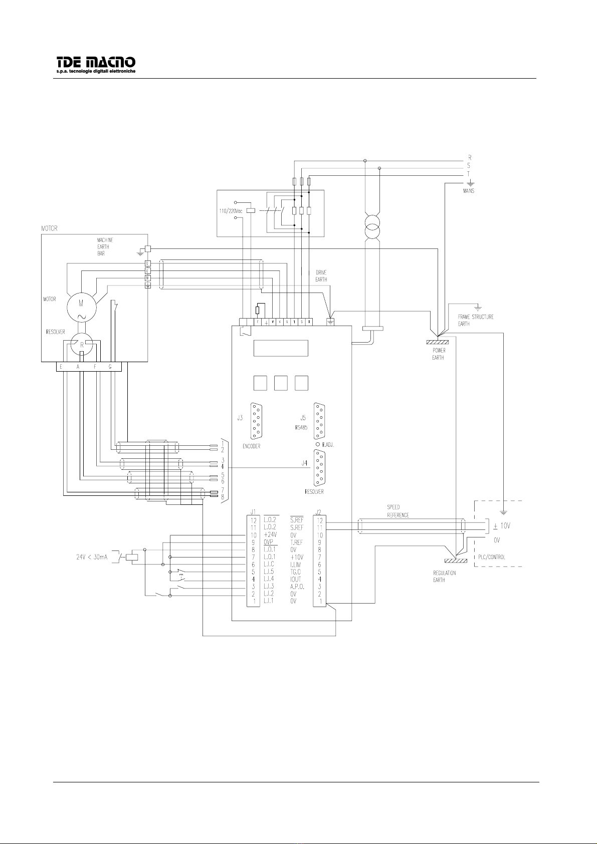
3.1. GENERAL SCHEME OF THE DSC DRIVE CONNECTIONS (3 X 220VAC)
+
F
Tr
RF
F
AUX. POWER
EXTERNAL ENABLE
RESET
REF. ENABLE
ON-LINE
SW SUPPLY WITH
380V/220V
30VA MAX.
TRANSFORMER
CONNECTOR FOR AUX.
POWER SUPPLY
(OPTION)
User manual 3-2 DSC/DSCT Series
3.2. GENERAL SCHEME OF DSCT DRIVE CONNECTIONS (3 X 380 VAC).
CONNECTOR FOR
AUX.POWER SUPPLY
AUX.POWER
EXTERNAL ENABLE
RESET
REFERENCE ENABLE
ON-LINE
K
SUPPLY WITH
380V/220V
30VA MAX.
TRANSFORMER
RSS
F
IC IC
RF
INTERNAL RELAY, ONLY FOR
SIZES 37 AND 47A
K2
K1
External switch-on current limitation
device only necessary for sizes 37A
and 47A
SW
(OPTION)
User manual 3-3 DSC/DSCT Series
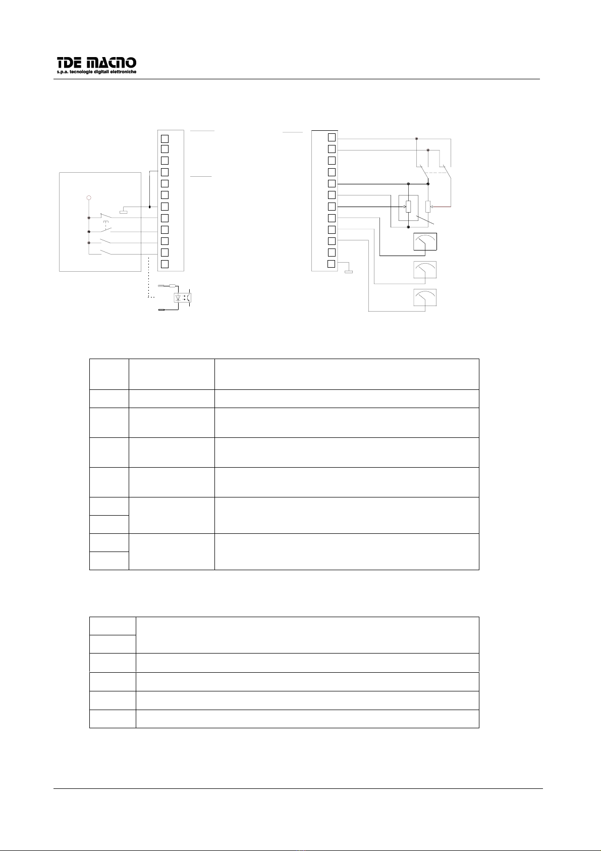
3.3. DEFAULT CONNECTIONS
J1
10
11
12
2
3
4
5
6
7
8
9
1
L.O.2
L.O.2
+24V
0VP
L.O.1
L.O.1
L.I.C
L.I.5
L.I.4
L.I.3
L.I.2
L.I.1
+24V
0
PLC o CNC
0V
0V
0V
A.P.O.
IOUT
TG.O
I.LIM
+10V
T.REF
S.REF
S.REF
0V
J2
0V
(∗
∗∗
∗)
(∗) If used it will be enabled with c31
10K
10
11
12
2
3
4
5
6
7
8
9
1
CW/CCW
1-2-3-4-5
6
Meaning and programming of digital I/O defaults (connector J1):
L.I.1 Torque enable Enables the drive to work with external torque reference
signal T.REF(±10V)
L.I.2 Run Enables the power to the motor.
L.I.3 Reference 1
enable
Enables the speed reference present in S.REF and
S.REF/.
L.I.4 Alarm reset Resets the alarms if the alarm causes have been
removed (minimum time of transition T=100mS).
L.I.5 External enable If this input is in the LOW state, the drive is in alarm A8,
and is not ready. (External emergency)
L.O.1
L.O.1/
Drive ready Active when the drive is ready to run (no alarm
presence).
L.O.2
L.O.2/
Drive running Active when the drive is running.
Meaning of the analog signals (connector J2):
S.REF
S.REF/
Differential speed reference input ±10V
I.LIM Maximum current limit 0÷+10V
TG.O Actual speed output -10V ÷+10V
IOUT Torque current request output -10V ÷+10V
A.P.O. configurable analogic output.
Note: L.I.1÷
÷÷
÷L.I.5 are comanded by signals between the range of 18V÷
÷÷
÷27V.

User manual 3-4 DSC/DSCT Series
3.4. KEYPAD
3.4.1. DESCRIPTION OF KEYBOARD OPERATION
The keyboard has three keys: 'S' (selection), '+' (increase) and '-' (decrease), and it has a display with four
and a half digits plus the decimal points and the minus sign '-'.
3.4.2. IDLE STATE
When the equipment is switched on, the keyboard displays "Stop"; if there are any alarms, the keyboard
flashes, displaying "Stop" intermittently. When the drive is working, if no special magnitude to be displayed
has been set (see 'c13'), magnitude d5 is displayed. The keyboard automatically returns to the rest state ten
seconds after the last operation, expecting that it doesn,t display an internal quantity or a digital state.
3.4.3. SETTING AND READING OF PARAMETERS AND CONNECTIONS
Press push-button 'S' and the keyboard will display the last parameter or magnitude selected, then, by using
the '+' and ' -' keys, scroll the menu up and down until you find the address of the parameter (P) or of the
connection (c) to be read and, if necessary, corrected. Next to the number of the parameter or connection
the letter 'r' appears if the parameter is reserved, 't' if it is TDE-reserved and 'n' if it is a parameter that can
be modified only when the drive is not running; all the reserved parameters are 'n'-type parameters which
may be modified only when the drive is not running (off-line).
On pressing key 'S', the parameter value is displayed and can therefore be read; press 'S' again to go back
to the menu and the system also automatically goes back to the menu 10 seconds after the beginning of the
display; to correct the parameter or connection value, when this is displayed, press the '-' and '+' keys at the
same time; the decimal point of the first figure at the left then starts to flash, which means that, from that
moment on, pressing the '-' and '+' keys changes the value set. The value is changed only from stop if the
parameter is OFFLINE or only after the access code, P50, has been set, if the parameter is reserved, or P80
for TDE-reserved parameters.
The TDE-reserved parameters and connections are not listed, unless access code P80 is set.
Once the value has been corrected, press 'S' to go back to the menu confirming the modified parameter or
connection; to exit without confirming, just wait for ten seconds and then the keyboard will display the
address discarding the changed value; if the value is not touched, just press 'S' to exit (the previous value
will be confirmed). Once in the menu, the keyboard automatically returns to the rest state.
3.4.4. DISPLAY OF INTERNAL MAGNITUDES
Move from the menu with the '+' or '-' keys until the address of the magnitude to be displayed 'dxx' appears;
on pressing 'S' the address disappears and the value is displayed.
Return to the menu from this state by just pressing 'S'; returning from the menu to the rest state is automatic
after 10 seconds.
3.4.5. DISPLAY OF I/O AND ALARMS
From the menu use the '+' and '-' keys to move to the address required for the digital inputs (i), the outputs
(o) and the alarms (A); the box to the right shows this and the state: 'H' = active (high), 'L' = not active (low).
To return to the rest state from this state, just press 'S'.
ATTENTION: For the complete list of all the magnitudes given by the keypad, refer to the chapter 9 on the
user manual.
User manual 3-5 DSC/DSCT Series
3.5. SAVING AND RESETTING PARAMETERS
The drive has a permanent memory (EEPROM) where parameters are stored. When the drive is switched
on, the drive transfers the parameters from the user permanent memory (EEPROM) to the working memory
(RAM). All the parameter changes are stored in the working memory (RAM); to save these changes in the
user permanent memory (EEPROM), activate the connection (c43=1).
If there is an EEPROM alarm (A2=H), it means that permanent values can not be read from the EEPROM; it
is necessary to reset the system: reset the default parameters (c41=1), and then save them in the user
permanent EEPROM memory (c43=1), overwriting the wrong parameters.
To return to the initial parameters in the permanent memory (EEPROM) after the changes in the working
memory (RAM) have been made, without switching off and on again, just activate connection c42 (c42=1).
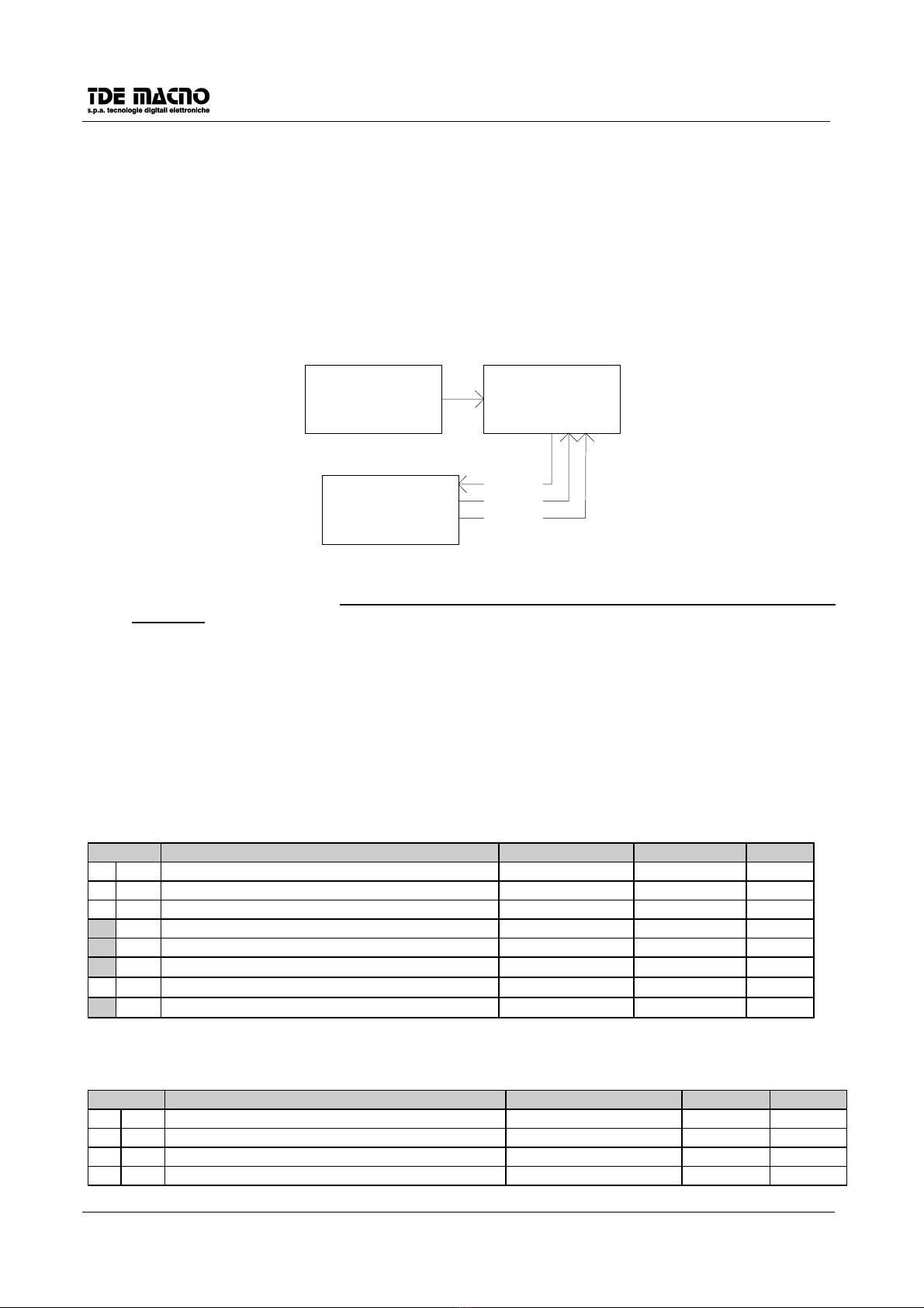
These procedures are explained below :
system memory with
default parameters
EPROM
working parameters
memory
RAM
C41
User parameters
permanent memory
EEPROM
C43
C42
Power on
N.B. As the default parameters are standard parameters which are certainly different from the customised
parameters, it is important to copy the parameters of the user permanent memory carefully after the
installation for each drive, so that, if necessary, they can be copied in a spare drive, or if the memory
is resetted with the default parameters.
3.6. DESCRIPTION OF FONDAMENTAL DATA
In the following are described the parameters, the connections and the minimum displaying magnitudes
necessary for the initial function of the drive. To have the first general vision of all the data prepared for the
customer it’s necessary to read the paragraph 9 of the manual user.
3.6.1. PARAMETERS
(Note: n= off-line, r=reserved customer, t= TDE customer)
SECT. DESCRIPTION FIELD DEFAULT Notes
P 1 JOG 1 speed ±100.0% 0.0%
P 2 JOG 2 speed ±100.0% 0.0%
P 3 JOG 3 speed ±100.0% 0.0%
P 23 Speed loop proportional gain 0.5-100.0 4.0
P 24 Speed loop lead constant time 4.0-150.0 ms 40.0 ms
P50 Reserved parameter access key 0÷9999 n
P 51 Drive identification number for the serial line 1÷255 255 r
P52 Setting maximum motor speed (rpm/1') 375÷19000 2500 r
3.6.2. CONNECTIONS
(Note: n = off-line , r = reserved to the customer, t = TDE-reserved)
CON. DESCRIPTION RANGE DEFAULT Notes
c 26 Ramp inclusion 0(excluded) 1(included) 0
c 41 Reset default values 0(disabled) 1(reset) 0 n
c 42 Reset EEPROM values 0(disabled) 1(reset) 0 n
c 43 EEPROM writing 0(disabled) 1(reset) 0 n

User manual 3-6 DSC/DSCT Series
3.7. GETTING STARTED
1. Verify that the connections are well done, that the terminals are well tighten and that the correct resolver
cable is used (see par 5.1).
2. Disconnect the power terminals of the motor.
3. Supply the drive and after a laps of time it will appear at the display the stable term “ stop” if there are no
alarms, light blinks if there are.
4. Configure the drive parameters: inputs (c1 - c5), outputs(c7-c8), and the motor parameters, motor
current (P56), motor poles (P53), resolver poles (P54), ecc.
5. Set at a low value (5%) the internal limits, P35,P36, and set to zero the velocity reference.
6. Reconnect the power terminals of the motor and start running (L.I.2).
7. If no alarm appears, on the display will appear the motors speed in RPM.
8. The motor must be in stillstand the reference is digital or moving very slowly if analog.
9. Setup the limits P35 P36 and calibrate if necessary the speed offset with the P4 parameter.
10. Give some reference and verify the correct working, in particular for a correct speed and eventually tune
the controller parameters (P23, P24) for a better dynamical response of the drive.
11. Execute motor cycles and see that everything is correct.
12. Save the parameters in EEPROM.
ADVISING: If during the operativity just explained, in particular at points 8 and 10, the motor goes over
cycles or it doesn’t move or it moves in kicking way, verify the correct execution of the electric cables.
The drive is already tuned to the motor specified at the ordering.
3.8. MALFUNCTIONING WITH ALARM SIGNAL : DIAGNOSIS
SAFETY ACTIVE DESCRIPTION REMEDIES
A1 Internal supply
error
The internal voltages are
incorrect
Check the +24V in the pin J1-9 and J1-10
A2
RAM , EEPROM
alarm
The drive reads wrong
parameter values
If the problem remains after turning on/off the drive, it
is necessary to make the C41 configuration
(reloading default values) or C42 (reloading EEPROM
values) and than use C43 (EEPROM writing). See
par. 3.5
A3 Power alarm
The output current from the
drive has reached such
levels that the saturation
control circuit of the
I.G.B.T. has intervened;
this may be caused by an
overcurrent due to
dispersion in the cables or
in the motor or to a short
circuit between the drive
output phases. Or it may be
due to a breakdown in the
regulation.
Check the connection cables particularly on the motor
side of the terminal block to remove any dispersion or
short-circuiting; check the insulation of the motor
itself, doing a dielectric rigidity test, and if necessary
replace it.
Check that the drive power circuit is working by
making it run after disconnecting the motor; if the
safety device intervenes the power circuit is
damaged.
If the safety device only intervenes during working it
could be a matter of regulation (replace it along with
the current transducers) or vibrations causing voltage
transients.
A4 Radiator thermal
switch alarm
The radiator temperature
sensor has switched on
because the radiator
temperature is too high.
Check the drive cooling circuit ; the ventilator, its feed
and the slits and filters for the entry of air into the
cabinet ; if necessary replace them or clean them
and ensure that the ambient temperature (near to the
drive) is within the permitted limits for the technical
characteristics.
If everything is in order and the alarm continues even
when the drive is cold check the connecting wires to
the thermal switch.

User manual 3-7 DSC/DSCT Series
SAFETY ACTIVE DESCRIPTION REMEDIES
A5 Motor thermal
switch alarm
The motor temperature
sensor has switched on
because of excessive coil
temperature.
Check the motor cooling circuit is complete ; the
ventilator, its feed, the slits and filters for the entry of
air, and if necessary replace or clean them, and also
check that the ambient temperature (near to the
motor) is within the permitted limits for the technical
characteristics.
If everything is in order and the alarm signal is still on
even when the motor is cold, check the connector
wires of the thermal probe and of every auxiliary
devices.
If it’s used a motor with thermal bimetallic protection, if this is
measured between pins 1 and 2 of J4 it must be closed. If it’s used
a motor with thermal protection like PTC, from pins 1 and 2 of J4 it
must be measured it’s nominal value at the corrisponding ambient
temperature.
A6 Motor in thermal
overload
The motor overload safety
electronic device has been
activated by excessive
current absorption for
prolonged period.
Check the motor load and consider if its reduction
may stop the intervention of the safety function.
Check the level of the setting thermal current, if
necessary correct it, and also check that the value of
the thermal constant is sufficiently long.
Check the power of the motor being adequate to the
load and if necessary increase it.
A7 Resolver failure Resolver failure indicates
that the drive does not find
its proper resolver
connection
Check the resolver connections and that all
connections have been made according to the
connection scheme (see motor user’s manual and
connection scheme).
Check the resolver shield and grounds being
connected properly (in particular the resolver shield
must be wired to pin 1 or 2 of J6, and then the 0V
must be grounded).
A8
Intervention of
the external
alarm
The external enable signal
is no more present, and
the drive has not the
consent to work
The external safety has removed the enable signal to
the drive: give it back and reset.
The continuity of the connection has been lost; check
and remove the fault.
A9 Overspeed The drive indicates that
motor speed is above the
max. allowed. (P52)
Check the parameters that change the motor
dynamics (P23, P24, P25).
A10 Minimum voltage
in the DC power
circuit
The voltage of the
intermediate circuit of the
drive is below the
minimum range.
The safety functions is
tripped when the input
voltage drops below the
permitted value
Undervoltage may occur when the main transformer
power is not sufficient to support the loads, or in case
that there is not the correct 220 AC three phase
voltage (for instance one phase is not powered).
Check the voltage in RST .
A11 Overvoltage of
the DC power
circuit
The voltage of the
intermediate voltage circuit
is strongly increased due
to excessive regenerative
energy coming from the
motor, e.g. in slow down
phase, and the limit of
overtension is exceeded
This alarm can happen if the motor is often breaking
in his working cycle. Even overvoltage on the mains
side can lead to the intervention of this safety function.
If the drive has a clamping circuit check that the value
of the resistor is not too high to absorb the peak
power.
Check, if the resistor is not heating up, its continuity,
the connections and functionality of the circuit itself.

User manual 3-8 DSC/DSCT Series
SAFETY ACTIVE DESCRIPTION REMEDIES
A12 Input
configuration
error
Two digital input were set
with the same function.
Check inputs configuration.
A13 pole setting error The drive has been set
with a wrong poles number
(P53, P54).
Check poles number.
A14 Mains
connections error
Motor phases U,V,W are
inverted.
Check the sequence of motor phases.

User manual 4-1 DSC/DSCT Series
4. ANTI-INTERFERENCE MEASURES
Electrical and electronic equipment can interfere each other through the mains connections or other metal
connections between each other. In order to minimise or eliminate this reciprocal interference it is necessary
the drive being correctly installed in conjunction with anti-interference devices (if required).
The following advice regards a mains power supply which is not disturbed. If interference exists other
measures must be taken to reduce the interference itself.
In these latter cases giving general advice is not possible and if the anti-interference measures do not lead
the desired results we would kindly ask you please to contact TDE MACNO.
•Ensure that all the equipment in the cabinet is well connected to the ground bar using short cables with
starconnections. In particular , it is important that any control equipment connected to the drive, e.g. PLC,
is grounded by using short wires.
•The drive must be fixed with screws and washers to ensure a good electrical connection between the
external container and the metallic support, connected to ground, and to the switchboard. If necessary
remove the paint to ensure a good contact.
•For the motor connection use only shielded or armoured cable and connect the shielding to ground both
at the drive end and at the motor end. If it is not possible to use shielded cable the motor cables should
be placed in a metal channel which is connected to ground.
•Keep the motor connection, drive and control connection cables separate from each other and at a
distance from each other.
•For the braking resistance cable connection use shielded cable connecting the shield to ground on both
sides, the drive side and the resistor side.
•Lay the control cables at a distance of at least 10 cm from any parallel power cables. In this case too it is
advisable to use a separate metal channel which is also connected to ground. If the control cables should
cross over the power cables maintain a cross-over angle of 90°.
•Ensure that any RC groups or flywheel diode for coils for the remote switches, relays and other
electromagnetic switches installed in the same cabinet as the drive are mounted directly onto the coil
connections themselves.
•Make all connections of control, measuring and regulation external systems with shielded cables.
•Cables which can radiate interference must be placed separately and distant from the drive control
cables.
If the drive operates in a particularly noise sensitive environment it is also necessary to take the following
measures to reduce the conducted and radiated interference:
•Use the DSC or DSCT drive with an external EMC filter (Shaffner, …).
•Take all necessary measures with regard to the cabinet thus to block radiated emissions, like grounding
all metal parts, the use of minimum hole openings in the external walls and the use of conducting gasket
User manual 5-1 DSC/DSCT Series
5. DESCRIPTION OF THE SIGNALS ON THE CONNECTORS
5.1. CONNECTING CABLE TO RESOLVER (CONNECTOR J4)
DB9 FEMALE TYPE CONNECTOR TO BE CONNECTED TO RESOLVER AS SHOWN IN THE FOLLOWING FIGURE
J4
DB9 FEMALE TYPE CONNECTOR MOTOR
CONNECTOR RESOLVER
TRANSF. RATIO
1: 0.5
1: 0.45
R1
R3
S1
REF
0REF
0COS
3
4
5
RESOLVER FEEDER OUTLET
(6,5 VOLT RMS - 7,8 KHz - MAX 20mA)
RESOLVER SIGNAL INPUT
RESOLVER SIGNAL INPUT
COS
0SIN
6
8
S3
S4
S2SIN
SP6
0SP6
7
1
2
MOTOR THERMAL SW ITCH
J2-10V
CABLE
CONNECTING
SWITCH
THERMAL
MOTOR
THEY MUST HAVE THE SAME FEATURES.
THE RESOLVER MUST BE OF THE SAME TYPE ALREADY USED, SEE TABLE, OR
RAP.TRAS. 0.5RESOLVER ARTUS ES. 26S19RX452b.F
CABLE : INTERCOND SPECIALFLEX H
fi
g
. 1
USED TAMAGAWA ES. TS2640N71E10
4x(2x0.25SK) COD. 2MB 24P 04R
RAP.TRAS. 0.5
PLUS EXTERNAL SHIELD.
THE SHIELD ON THE CONNECTOR SIDE J4 MUST BE CONNECTED TO
TERMINAL 1 OF CONNECTOR J2 AND FINALLY CONNECTED TO THE
THE CONNECTING CABLE MUST BE 4-BIGHTS PLAIED AND SHIELDED
ADJUSTING EARTH BAR AS SHOW IN PARAGRAPH 1.2.
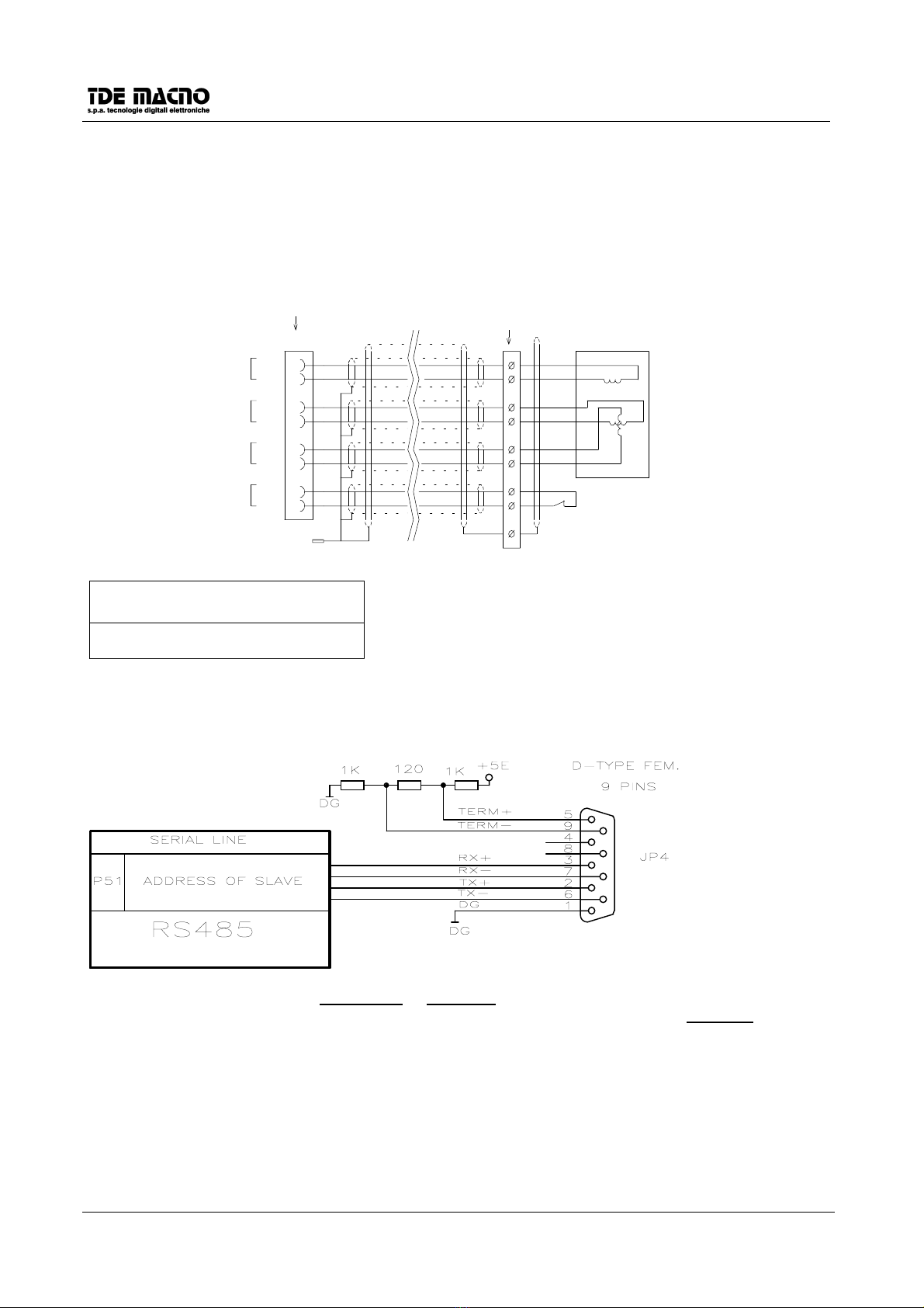
5.2. SERIAL LINE CONNECTOR (CONNECTOR J5)
The serial line communicates in half duplex on four wires: RX+ and RX- are receiving wires for the drive
while TX+ and TX- are transmitting wires. It can be done the connection with only two wires connecting
together RX+ and TX+, and RX- and TX- (each couple of wires must be twisted).
There is the possibility to ‘terminate’ the connection with 120Ωof impedance and polarizing the line
connecting the terminals 5 with 3 and 9 with 7.
It is available a simple PC supervisor software ( DOS or Windows 95) for the DSC/DSCT series drives.

User manual 5-2 DSC/DSCT Series
5.3. SIGNALS ON THE CONNECTORS
5.3.1. LOGIC SIGNALS (CONNECTOR J1)
PIN FUNCTION DESCRIPTION PAR.
1 L.I.1
2 L.I.2
3 L.I.3
4 L.I.4
5 L.I.5
Logic configurable inputs
ON = +24Vdc (>18Vcc) 10mA max.
OFF = 0Vcc (<6Vcc)
All inputs are opto-insulated from the internal regulation.
7.1
6 L.I.C Common connection of the logic inputs. Connect to the negative pole of the
inputs supply.
7.1
7 L.O.1
8/L.O.1
Logic configurable output
Transistor NPN with free collector ( L.O.1 ) and emitter ( /L.O.1 ), insulated
from the regulation and protected from overvoltage.
In CONDUCTION when output is ACTIVE : +24 Vdc 30 mA max;
7.2
90VP
10 +24V
Internal supply +24V, insulated from the regulation
11 L.O.2
12 /L.O.2
Logic configurable output
Transistor NPN with free collector ( L.O.1 ) and emitter ( /L.O.1 ), insulated
from the regulation and protected from overvoltage.
In CONDUCTION when output is ACTIVE : +24 Vdc 30 mA max;
7.2
5.3.2. ANALOG SIGNALS (CONNECTOR J2)
PIN FUNCTION PAR.
10V
20V
Regulation 0V
3 A.P.O. Analog configurable output: ±10V /2mA
Default configuration: CURRENT REQUEST(c13=11)
7.3
4 I.OUT Current request output signal ±10V <2mA
5TG.O
Motor speed analog output ±10V <2mA
6 I.LIM Analog input Max. Current Limit 0÷+10V <0.5mA
7+10V
80V
+10V / 10mA max.
Stabilized power supply
9T.REF
Analog input Torque Reference ±10V <0.5mA
10 0V 0V of the speed reference
11 S.REF Speed reference differential input.
12 /S.REF ±2.5V÷±10V <0.5mA
5.3.3. FREQUENCY INPUT CONNECTOR (CONNECTOR J6)
PIN FUNCTION
1 FA Channel /A input.
2 FA/ (F) Channel A/ input or frequency input.
3 FB Channel B input.
4 FA (UP/DOWN) Channel B/ input or UP/DOWN
5 0DG 0V of the frequency input

User manual 5-3 DSC/DSCT Series
5.4. SIGNALS ENCODER EMULATION (CONNECTOR J3)
The frequency of the signals depends on the motor revolutions, the number of resolver poles and the
selection made (see connection c10, c11 and c12) and their behaviour in time depends on the tachometer
signal and on c10 as shown in the figures below
MALE DB9 CONNECTOR
J3
d5>0 con c10=0
d5<0 con c10=1
d5>0 con c10=1
d5<0 con c10=0
1
2
3
4
5
6
7
8
9
/B
B
/A
A
VS (+)
/C
C
0VS
CHANNEL B
CHANNEL A
CHANNEL C
+VS
0VS
+VS
A
B0VS
+VS
+VS
0VS
C
0VS
+VS
0VS
*A
*B
+VS
0VS
*C
+VS
0VS
A
+VS
0VS
B
+VS
0VS
C
+VS
0VS
+VS
0VS
*A
*B
+VS
0VS
*C
5V≤VS≤30V
Fmax=500KHz for channel
The encoder simulated outputs are all driven by a “ LINE DRIVER” type ET7272.Their level in the standard
drive version is referred to +5V and than it is connect to the internal supply (TTL +5V). In option there is the
possibility to refer the signal level to an external supply whose value must be between +5V and +24V
(connection on terminals 5 and 9, (TTL 24V)).
For the immunity it is better to use a differential input (where the signal arrives) in order to avoid loops with
zero reference; to limit noise effects it is better to load this input (10mA max).
It is necessary to use a twisted shielded cabe to make a proper connection.
Attention, the external power supply zero is connected with the drive zero; (it is not
optoisolated).
Attention, for the encoder simulation with external supply (standard drive version)
you must not connect the terminal 5 (VS) because it could seriousuly demage the
drive.
This manual suits for next models
16
Table of contents


