Tecumseh 5267-1900 User manual
OWNER'S MANUAL
32"- 5 H.P. RIDING MOWER
MODEL 5267-1900
WARRANTY
Lawn Mower Division Warranty Policy.
ONE YEAR LIMITED WARRANTY
For one (1) year from date of purchase by the first'consumer for residential use (thirty (30) days
commercial use), Lawn Mower Division warrants that it will replace free of charge, including
labor, any original part of anyLawn Mower Division product found to be defective by any
authorized Service Dealer orthe factory, except the battery which isWarranted for ninety (90) days
from date of purchase. 1
This warranty does not cover engines, transmissions,_trensaxles or differentials (these items are
covered by their manufacturer's own warranty). This warranty does not cover parts that have
faile d due to normal wear or parts that have failed subject to misuse or abuse. Transportation of
the unit or parts to and from an authorized Service Dealer or the factory isthe responsibility ofthe
owner.
Astep by step explanation as to what procedure should be followed for this Warranty is;
1. If a part becomes defective, contact t_te store where the unit was purchased for the name
and address of the authorized Service Dealer nearest to you.
2. If you cannot locate an authorized Service Dealer, write Service Department ofLawn Mower
Division, for the name and address of the authorized Service Dealer in your area.
3. Return the defective productoalong with proof ofpurchase tosuch authorized Service Dealer
for replacement of any defective part where covered by this warranty.
There is no other express warranty. Implied warranties, including those of merchantability and
fitness for a particular purpose are limited to one (1) year from date of purchase. Liability for
incidental or consequential damages are excluded.
Some states do not allow limitations on how long an implied warranty lasts, so the above
limitation may not apply to you. Some states do not allow the exclusion of incidental or
consequential damages, so the above exclusion may not apply to you. This warranty gives you
specific legal rights, and you may have other rights which vary from state to state.
Lawn Mower Division P.O. Box 377 Des Moines. Iowa 50302
'UNIT PARTS AND SERVICE
This manual contains instructions for safety, assembly and maintenance. Read this manual carefully and
completely so that you will know proper assembly, use and care of your unit. Also fill in and mail the warranty
registration card packed with the unit. For service other than covered in this manual, contact an authorized
service dealer. A nationwide parts and service organization has been established to provide locally available
parts and service. A list of authorized parts distributors has been included in this manual. When ordering
repair parts, always give the following information: 1. The Part Name; 2. The Part Number; 3. The
Quantity desired; 4. The Full (eight digit) Model Number of the unit. The model number will be found on a
plate attached to the unit.
Look for this symbol. It means -- ATTENTION! BECOME ALERT! A
HAZARD TO OPERATOR. BYSTANDERS, PROPERTY OR UNIT
MAY EXIST.
=art No. 62211 Rev. 3/82
LAWN MOWER DIVISION
P.O. BOX 377
DES MOINES. IOWA 50302 1182
Pwinlecl in U S A
It isimportant when using your Riding Mower that certain precautions betaken to
prevent injury or damage. Please read the following list of precautions before you
assemble or use yourRidingMower.
1. Know the controls and howto stop quickly. Read the
Owner's Manual. Wear safety glasses or eye shields when
assembling or operating unit.
2. Disengage ell attachment clutches, shift to neutral,
and set parking brake before attempting to start the en-
gine. Unless these steps are followed, the engine will not
start because of safety interlock or lockouts. When
starting your engine or mower equipped with a pull
starter, stand firm and make sure your feet are well away
from the blade(s).
3. When using vehicle with mower:
A. Do not operate this mower without either the
chute deflector or an entire grass catcher in place.
B. Mow only in daylight or good artificial light.
C. Never make a cutting height adjustment of
housing guide wheel while eKgine is running.
D. Shut engine off when removing grass catcher
and/or unclogging chute.
E. DO not operate mower when barefooted. Always
wear substantial footwear, preferably steel-toed
shoes. Do not wear loose fitting clothing that
could get caught in any moving parts. ,
F. Always keep clear of discharge chute or any
moving parts while engine is running.
4. Always place the blade control lever in a disengaged
position when not cutting grass, such as when crossing a
gravel driveway or roadway and when transporting the
mower.
5. Disengage power to attachments, stop engine,
remove ignition key. and set parking brake before leaving
operator position. AlWays dismount on the side away
from the discharge chute.
6. Handle gasoline with care; it is highly flammable.
A. Use only approved gasoline containers.
B. Never remove cap or add gasoline to a running or
hot engine or fill fuel tank indoors. Wipe up spilled
gasoline,
C. Check your fuel supply before each '_seallowing
space for expansion as the heat of the engine
and/or sun can cause gasline to expand.
D. Never store gasoline or equipment with gasoline
in the tank inside of a building where fumes may
reach an open flame or spark. Never stoze your
mower for prolonged periods {more than 15 days}
with gasoline in the tank, Store gasoline and your
mower in a locked, safe storage area secure from
children and others.
7. Allow engine to cool before storing in any enclosure.
8. To reduce fire hazard, keep engine free of grass,
leaves, or excessive grease.
9. Do not allow children to operate the mower. Never
allow adults to operate it without proper instructions.
10. Never attempt to carry passengers. TheiPsafsty, as
well as yours, may be in danger. Do not allow others,
including children and pets in the area while operating the
mower. Be especially watchful for children and passersby.
Place the blade control lever in • disengaged position and
stop the engine while others ere in the vicinity of:the
mower.
11. When using any attachments, never direct discharge
of material toward bystanders or allow anyone near the
vehicle while in operation.
12. Clear work area of objects which may be picked up
and discharged by the mower. {These include rocks,
stones, wires, cans, boards, branches, bones, and other
foreign objects).
13. Vehicles and attachments should be stopped and in-
spected for damage if vibration devolopes or after striking
a foreign object. Any damage should be repaired before
restarting and operating the equipment.
14. Stay alert for holes in terrain and other hidden
hazards. Exercise care when mowing around fixed objects
in order to prevent blade{s} from striking it. Never deliber-
ately run a power mower over any foreign object. Always
disengage blade control before attempting to remove the
mower from a hole or other obstruction.
15. Keep all nuts, bolts and screws tight to be sure equip-
ment is in safe working condition. Check blade mount
nuts or bolts for proper tightness at frequent intervals.
16. Keep vehicle and attachments in good opersting con-
dition and keep safety devices in place.
17. Disengage power to attachments, stop engine.
remove ignition k_y, set parking brake and remove spark
plug before working on any part of the mower or making
any adjustments.
18. Do not change engine governor settings or over-
speed engine.
1g. Check grass catcher bag frequently for wear end/or
deterioration. Replace with new bag for protection.
20. Do not stop or start suddenly, especially when going
uphill or downhill. Mow slowly when On slopes and mow
up and down the slope, never across it. On slopes, bevary
cautious and avoid sharp turns to prevent tipping or loss of
control. Exercise caution when changing direction on
slopes. Never operate your lawn mower in wet or slippery
grass where direction is unsure or at a speed which could
cause a skid. Avoid shifting gears on an incline whenever
possible, If necessary, be sure brake is epplled when
shifting.
21. Watch out for traffic when crossing or near
roadways.
22. Do not run the engine indoors. Open doors if engine
is run in garage. Exhaust fumes contain carbon monoxide
gas w_ich is odorless and a deadly poison.
23. Use care when pulling loads or using heavy equip-
ment.
A. Use'only approved drawbar hitch points.
B. Limit loads to those youcan safely control.
C. Do not turn sharply. Use care when backing.
D. Never shift gears to reverse your direction until
the mower comes to a complete stop. Do not
operate your mower with the parking brake :
engaged.
24. Take all possible precautions when leaving the
vehicle unattended, such as disengaging the power take-
off. lowering attachments, shifting into neutral, setting
the parking brake, stopping the engine, and removing the
key.
--2--

' Record the following information about your unit so that you will be able to provide it in case of loss or theft.
PURCHASE DATE: _MODEL NO.: 5267-1900 CODE NO.:
DEALER'S NAME & ADDRESS
CITY STATE TELEPHONE
WARNING
This unit is equipped with an internal combustion
engine and should not be used on or near any
unimproved forest-covered, brush-covered or
grass-covered land unless the engine's exhaust
system is equipped with a spark arrester meeting
app)icable state or local laws (if any). If a spark
arrester is used, it should be maintained in effective
working order by the operator.
CONTENTS OF SHIPPING CARTON
1 - 32 inch Riding Mower
1-Steering Wheel (with roll pin partially installed)
1-Engine Manual
TOOLS REQUIRED FOR ASSEMBLY
1 - '/2 inch Wrench (or adjustable wrench)
1 - 7/16 inch Wrench (or adjustable wrench)
1- Hammer (plastic or rawhide preferred)
DANGER
The operation of any powered equipment can result
in foreign objects being thrown into the eyes, which
can result in severe eye damage. Always wear safety
glasses or eye shields while assembling or operating
power equipment.
STEERING WHEEL ASSEMBLY
1. Position front wheels straight forward.
2. Push steering wheel (figure 1) onto steering shaft.
3. With one spoke of steering wheel straight 0p, align
cross holes in steering wheel wit_ holes in steering shaft.
4. Drive roll pin through holes with hammer.
ROLL PIN
I
4. Fill gas tank (located on engine) with clean, fresh,
regular grade automotive gasoline. Low-lead gasoline is an
acceptable substitute. Do not use Ethyl, high octane
gasoline or GasohoL Re certain container is clean and free
from rust or foreign particles. Never use gasoline that may be
stale from long periods of storage in the container.
DANGER A
Never fill the gas tank while the engine is running or
is hot. Immediately wipe off any spilled gasoline
before attempting to start engine. I
5. Check tire pressure. Correct tire pressure is 12 to 15
pounds in each tire. Inflate all tires equally.
6. Check all nuts and bolts to be sure none are loose.
7. Check all adjustments listed in Adjustment section of
this manual to make sure unit is properly adjusted.
8. Check to make sure that spark plug is tightened
securely into engine and spark plug wire is attached to spark
plug.
/
OIL FILL CAP
The operation of any powered outdoor equip-
ment can result in foreign objects being thrown
into the eyes, which Can result in severe eye
damage, Always wear safety glasses or eye
shields before beginning riding mower operation. We
recommend standard safety glasses or Wide Vision Safety
Mask for over spectacles.
Familiarize yourself with the equipment and with the
Operational Precautions.
STEERING WHEEL
TO SERVICE ENGINE
1. Place unit so engine is in a level position.
2. Fill engine crankcase with oil. See Engine Operation
and Maintenance Manual for proper procedure.
3. Replace oil fill cap (figure 2) and tighten securely.
ADANGER A
DO NOT operate this mower without either the
chute deflector or an entire grass catcher in place. A
riding mower can be dangerous to operate if
misused. On slopes, be very cautious and avoid
sharp turns to prevent tipping or loss of control.
Your new mower will give years of service if cared for
properly. Never run into trees, curbs, etc. Service regularly
--3--
and store in dry area. Operate your mower at slow speeds
until you become familiar with the machine. Avoid sharp
turns at high speed and uphill or downhill turns. Operate
mower carefully. Be especially cautious on hills• When
riding down inclines, keep shift control in low speed with
brake-clutch pedal out. This helps the engine control the
speed. Use brake for fast stops on hills.
CONTROLS
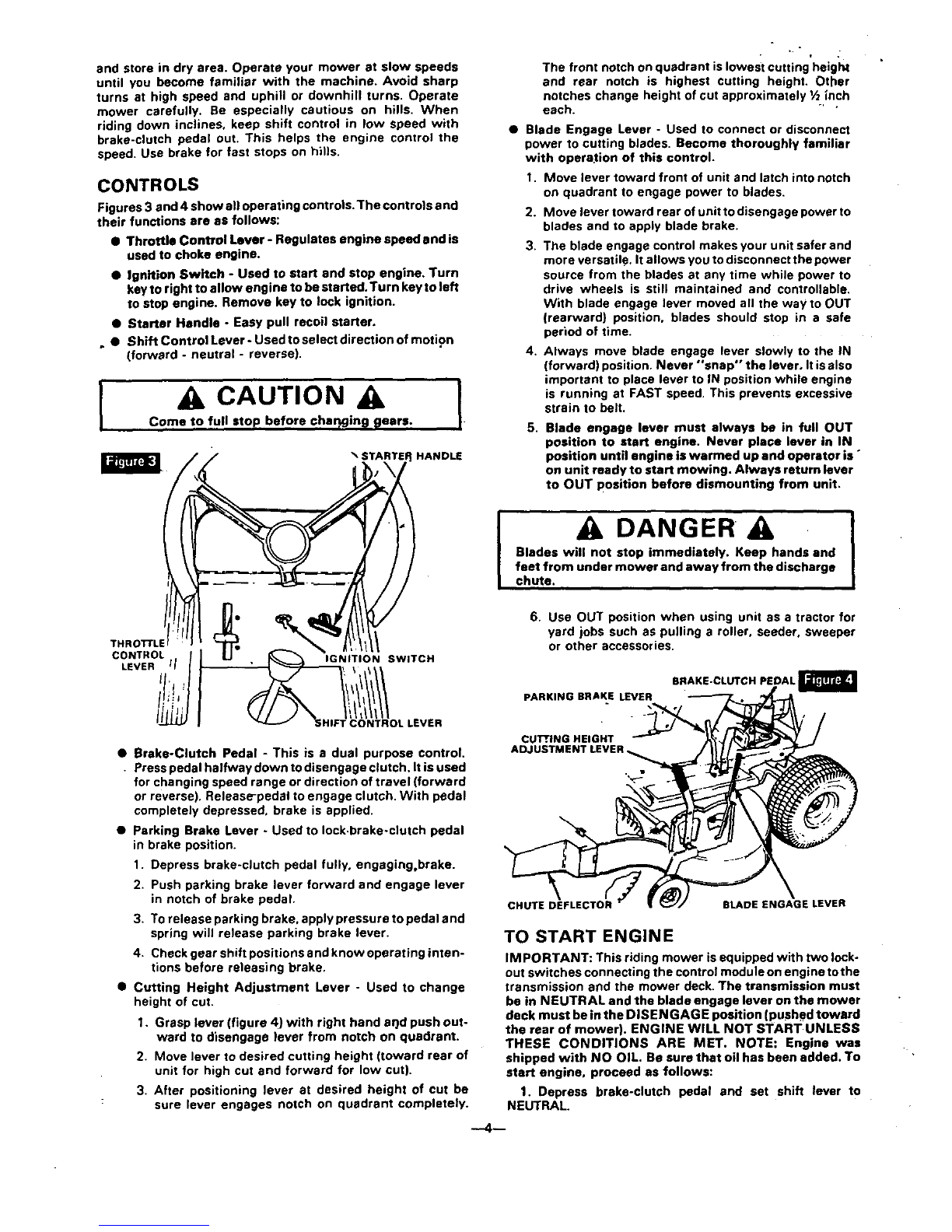
Figures 3 and 4 show all operating controls.The controls end
their functions are as follows:
• Throttle Control Lever - Regulates engine speed and is
used to choke engine.
•Ignition Switch - Used to start end stop engine. Turn
key to right to allow engine to be started. Turn key to left
to stop engine. Remove key to lock ignition.
•Starter Handle - Easy pull recoil starter.
••Shift Control Lever- Used toselect direction of motion
(forward -neutral - reverse).
,CAUTION
Come to full stop before char_gin_ _ears.
HANDLE
• f
The front notch on quadrant islowest cutting height
and rear notch is highest cutting height. Other
notches change height of cut approximately 1/2inch
each. "'"
•Blade Engage Lever - Used to connect or disconnect
power to cutting blades. Become thoroughly familiar
with opera,ion of this control.
1. Move lever toward front of unit and latch into notch
on quadrant to engage power to blades.
2. Move lever toward rearofunittodisengagepower to
blades and to apply blade brake.
3. The blade engage control makes your unit safer and
more versatile. It allows you to disconnect the power
source from the blades at any time while power to
drive wheels is still maintained and controllable•
With blade engage lever moved all the way to OUT
(rearward) position, blades should stop in a safe
period of time.
4. Always move blade engage lever slowly to the IN
(forward) position. Never *'snap" the lever, It isalso
important to place lever to IN position while engine
is running at FAST speed. This prevents excessive
strain to belt.
5. Blade engage lever must always be in full OUT
position to start engine. Never place lever in IN
position until engine is warmed up and operator is °
on unit ready to start mowing. Always return lever
to OUT position before dismounting from unit.
m
m
,
DANGER
Blades will not stop immediately. Keep hands and
feet from under mower and away from the discharge
chute. I
THROTrLE
CONTROL !IGNITION SWITCH
LEVER 'l /
tl'!
!ti:, / .EVEn
6. Use OUT position when using unit as a tractor for
yard jobs such as pulling a roller, seeder, sweeper
or other accessories.
BRAKE-CLUTCH PEDAL
PARKING BRAKE LEVER
•Brake-Clutch Pedal - This is adual purpose control.
Press pedal halfway down to disengage clutch. It isused
for changing speed range or direction of travel (forward
or reverse). Release-pedal to engage clutch. With pedal
completely depressed, brake is applied.
CUl!', ING HEIGHT
ADJ
•Parking Brake Lever - Used to lock.brake-clutch pedal
in brake position.
1. Depress brake-clutch pedal fully, engaging,brake.
2. Push parking brake lever forward and engage lever
in notch of brake pedal.
3. To release parking brake, apply pressure to pedal and
spring will release parking brake lever.
4. Check gear shift positions and know operating inten-
tions before releasing brake.
•Cutting Height Adjustment Lever - Used to change
height of cuL
1. Grasp lever (figure 4) with right hand arid push out-
ward to disengage lever from notch on quadrant.
2. Move lever to desired cutting height (toward rear of
unit for high cut and forward for low cut).
3. After positioning lever at desired height of cut be
: sure lever engages notch on quadrant completely.
CHUTE DEFLECTOR BLADE ENGAGE LEVER
TO START ENGINE
IMPORTANT: This riding mower is equipped with two lock-
out switches connecting the control module on engine tothe
transmission end the mower deck. The transmission must
be in NEUTRAL and the blade engage lever on the mower
deck must be in the DISEN GAG E position (pushed toward
the rear of mower). ENGINE WILL NOT START UNLESS
THESE CONDITIONS ARE MET. NOTE: Engine was
shipped with NO OIL. Be sure that oil has been added. To
start engine, proceed as follows:
1. Depress brake-clutch pedal and set shift lever to
NEUTRAL.
:2. Place blade engage lever to OUT position.
3, Place engine control lever to START position.
4. Turn ignition key to START.
5, Crank engine (pull starter handle).
6. After engine starts, move engine control lever to
desired engine speed.
DANGER
Never run engine indoors or in enclosed, poorly
ventilated areas. Engine exhaust contains carbon
monoxide, an odorless and deadly gas.
Keep hands, feet, hair and loose clothing away from
eny moving parts on engine or riding mower.
WARNING -Temperature of muffler and nearby areas
may exceed 150 ° F. Avoid these areas.
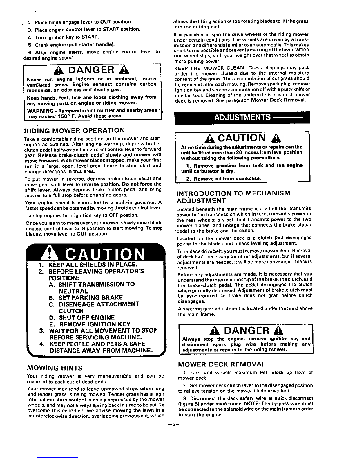
RIDING MOWER OPERATION
Take a comfortable riding position on the mower and start
engine as outlined. After engine warmup, depress brake-
clutch pedal halfway and move shift control lever to forward
gear. Release brake-clutch pedal slowly ar)d mower will
move forward. With mower blades stopped, make your first
run in a large, open. level area. Learn to stop. start and
change directions in this area.
To put mower in reverse, depress brake-clutch pedal and
move gear shift lever to reverse position. Do not force the
shift lever. Always depress brake-clutch pedal and bring
mower to a full stop before changing gears.
Your engine speed is controlled by a built-in governor. A
faster speed can be obtained by moving throttle control lever.
To stop engine, turn ignition key to OFF postion.
Once you learn to maneuver your mower, slowly move blade
engage control lever to IN position to start mowing. To stop
blades, move lever to OUT position.
1. KEEP ALL SHIELDS IN PLACE.
2. BEFORE LEAVING OPERATOR'S
POSITION:
A. SHIFT TRANSMISSION TO
NEUTRAL
B. SETPARKING BRAKE
C. DISENGAGE ATTACHMENT
CLUTCH
D. SHUT OFF ENGINE
Eo REMOVE IGNITION KEY
3. WAIT FOR ALL MOVEMENTTO STOP
BEFORE SERVICING MACHINE,
4. KEEP PEOPLE AND PETS A SAFE
DISTANCE AWAY FROM MACHINE.
allows the lifting action of the rotating blades to lift the grass
into the cutting path.
It is possible to spin the drive wheels of the riding mower
under certain conditions. The wheels are driven by atrans-
mission and differential similar to an automobile. This makes
short turns possible and prevents marring of the lawn. When
one wheel slips, shift your weight over that wheel to obtain
more pulling power. "
KEEP THE MOWER CLEAN. Grass clippings may pack
under the mower chassis due to the internal moisture
content of the grass. This accumulation of cut grass should
be removed after each mowing. Remove.spark plug, remove
ignition key and scrape accumulation off with a putty knife or
similar tool. Cleaning of the underside is easier if mower
deck is removed. See paragraph Mower Deck Removal.
ACAUTION A
At no time during the adjustments or repairs can the
unit be lifted more than 20 inches from level position
without taking the following precautions:
1. Remove gasoline from tank and run engine
until carburetor is dry.
2. Remove oil from crankcase.
INTRODUCTION TO MECHANISM
AD_JUSTMENT
Located beneath the main frame is a v-belt that transmits
power to the transmission which in turn, transmits power to
the rear wheels; a v-belt that transmits power to the two
mower blades; and linkage that connects the brake-clutch
•pedal to the brake and the clutch.
Located on the mower deck is a clutch that disengages
power to the blades and a deck leveling adjustment.
To replace drive belt. you must remove mower deck. Removal
of deck isn't necessary for other adjustments, but if several
adjustments are needed, it will be more convenient if deck is
removed.
Before any adjustments are made. it is necessary that you
understand the interrelationship of the brake, the clutch, and
the brake-clutch pedal. The pedal disengages the clutch
when partially depressed. Adjustment of brake_clutch must
be synchronized so brake does not grab before clutch
disengages.
Asteering gear adjustment is located under the hood above
the main frame.
]DANGER
Always stop the engine, remove ignition key and
disconnect spark plug wire before making any
adjustments or repairs to the riding mower.
MOWING HINTS
Your riding mower is very maneuverable and can be
reversed to back out of dead ends.
Your mower may tend to leave unmowed strips when long
and tender grass is being mowed. Tender grass has ahigh
internal moisture content is easily depressed by the mower
wheels, and may not always spring back in time to be cut. To
overcome this condition, we advise mowing the lawn in a
counterclockwise direction, overlapping previous cut. which
MOWER DECK REMOVAL
1. Turn unit wheels maximum left. Block up front of
mower deck.
2. Set mower deck clutch lever to the disengaged position
to relieve tension on the mower blade drive belt.
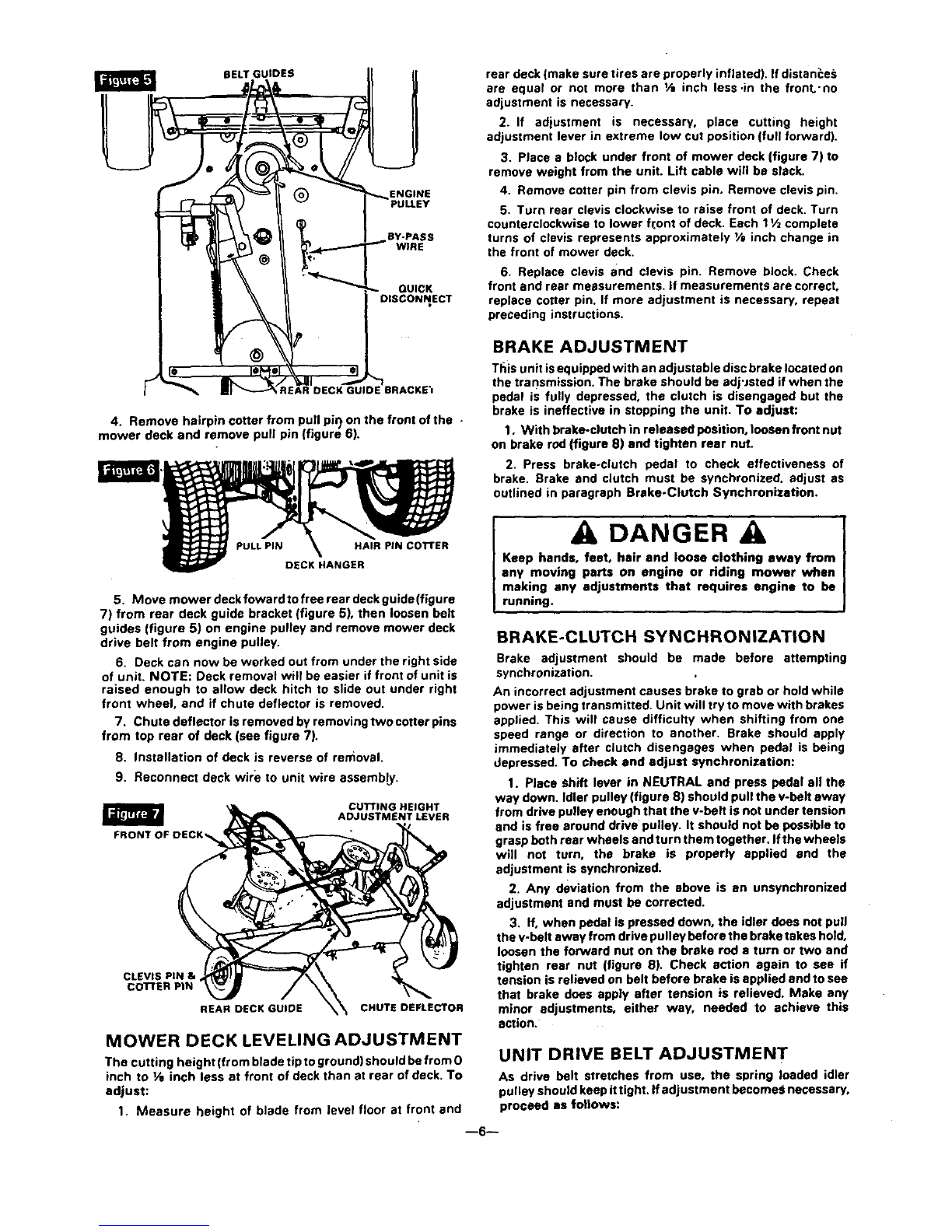
3. Disconnect the deck safety wire at quick disconnect
(figure 5) under main frame. NOTE: The by-pass wire must
be connected to the solenoid wire on the main frame in order
to start the engine.
--5--
BELT GUIDES
ENGINE
BY'PASS
WlHE
QUICK
"AR DECK GUIDE BRACKE'I
4. Remove hairpin cotter from pull pil) on the front of the -
mower deck and remove pull pin (figure 6).
5. Move mower deckfowardtofreerear deckguide(figure
7) from rear deck guide bracket (figure 5), then loosen belt
guides (figure 5) on engine pulley and remove mower deck
drive belt from engine pulley.
6. Deck can now be worked out from under the right side
of unit. NOTE: Deck removal wilt be easier if front of unit is
raised enough to allow deck hitch to slide out under right
front wheel, and if chute deflector is removed.
7. Chute deflector is removed by removing two cotter pins
from top rear of deck (see figure 7).
8. Installation of deck is reverse of removal.
9. Reconnect deck wire to unit wire assemb_.
CUTTING HEIGHT
ADJUSTMENT LEVER
_A
CLEVIS PIN &
co'n'ER PIN
REAR DECK GUIDE CHUTE DEFLECTOR
MOWER DECK LEVELING ADJUSTMENT
The cutting height (from blade tip to ground) should be from 0
inch to V, inch less at front of deck than st rear of deck. To
adjust:
1. Measure height of blade from level floor at front and
rear deck (make sure tires are properly inflated). If dlstan_:e_;
are equal or not more than I/a inch less .in the front'no
adjustment is necessary.
2. If adjustment is necessary, place cutting height
adjustment lever in extreme low cut position (full forward).
3. Place a block under front of mower deck (figure 7) to
remove weight from the unit. Lift cable will be slack.
4. Remove cotter pin from clevis pin. Remove clevis pin.
5. Turn rear clevis clockwise to raise front of deck. Turn
counterclockwise to lower fr.ont of deck. Each 11/z complete
turns of clevis represents approximately VB inch change in
the front of mower deck.
6. Replace clevis and clevis pin. Remove block. Check
front and rear measurements, if measurements are correct,
replace cotter pin. If more adjustment is necessary, repeat
preceding instructions.
BRAKE ADJUSTMENT
This unit isequipped with an adjustable disc brake located on
the transmission. The brake should be adj'Jsted if when the
pedal is fully depressed, the clutch is disengaged but the
brake is ineffective in stopping the unit. To adjust:
1. With brake-clutch in released position, loosen front nut
on brake rod (figure 8) and tighten rear nut.
2. Press brake-clutch pedal to check effectiveness of
brake. Brake and clutch must be synchronized, adjust as
outlined in paragraph Brake-Clutch Synchronization.
DANGER A
Keep hands, feet, hair and loose clothing away from
any moving parts on engine or riding mower when
making any adjustments that requires engine to be
running.
BRAKE-CLUTCH SYNCHRONIZATION
Brake adjustment should be made before attempting
synchronization.
An incorrect adjustment causes brake to grab or hold while
power is being transmitted. Unit will try to move with brakes
applied. This will cause difficulty when shifting from one
speed range or direction to another. Brake should apply
immediately after clutch disengages when pedal is being
depressed. To check and adjust synchronization:
1. Place shift lever in NEUTRAL and press pedal all the
way down. Idler pulley (figure 8) should pull the v-belt away
from drive pulley enough that the v-belt is not under tension
and is free around drive pulley. It should not be possible to
grasp both rear wheels and turn them together. Ifthe wheels
will not turn, the brake is properly applied and the
adjustment is synchronized.
2. Any deviation from the above is an unsynchronized
adjustment and must be corrected.
3. If, when pedal is pressed down, the idler does not pull
the v-belt away from drive pulley before the brake takes hold,
loosen the forward nut on the brake rod a turn or two and
tighten rear nut (figure 8). Check action again to see if
tension is relieved on belt before brake is applied and to see
that brake does apply after tension is relieved. Make any
minor adjustments, either way, needed to achieve this
action.
UNIT DRIVE BELT ADJUSTMENT
As drive belt stretches from use, the spring loaded idler
pulley should keep it tight. If adjustment becomes necessary,
proceed as follows:
--6--
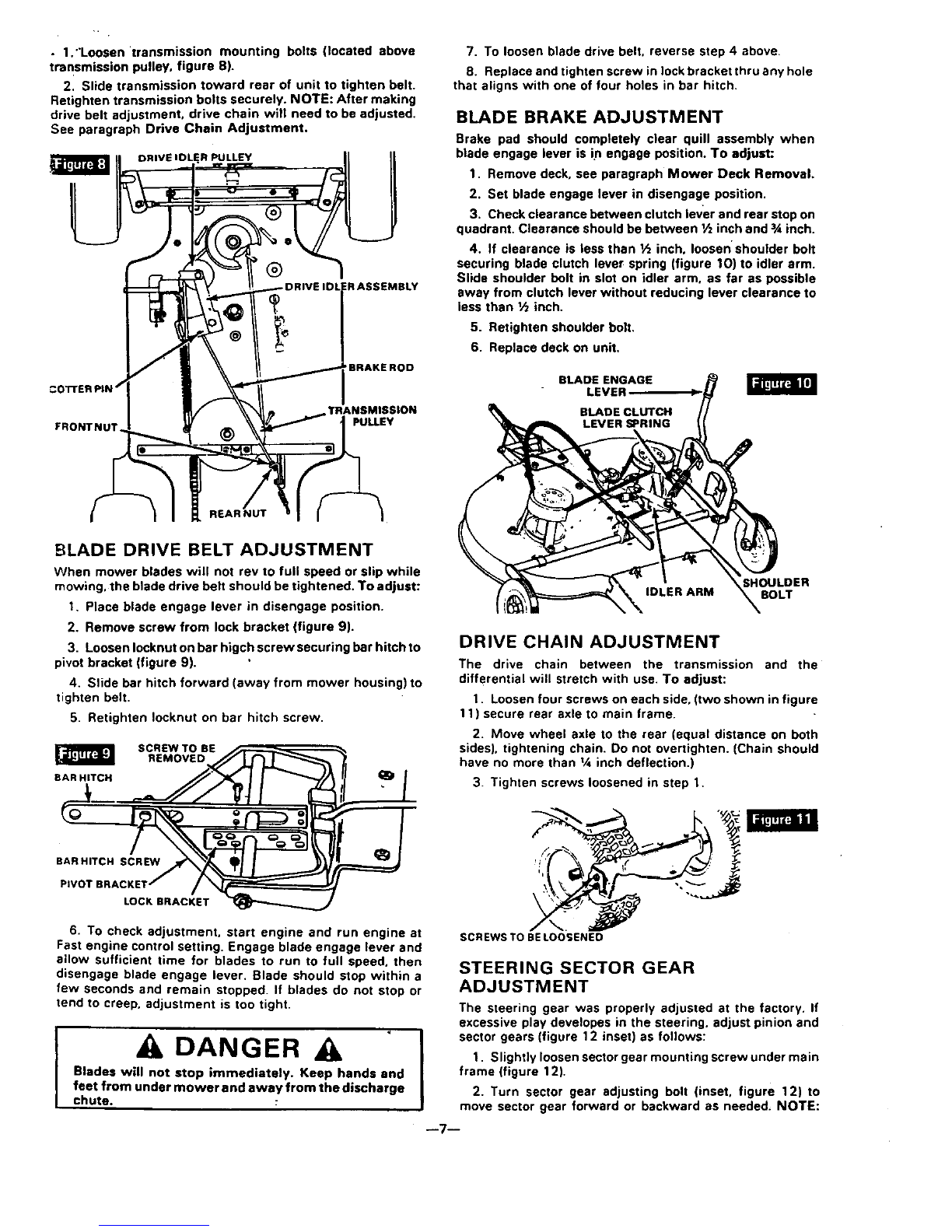
• 1,"Loosen transmission mounting bolts {located above
transmission pulley, figure 8).
2. Slide transmission toward rear of unit to tighten belt.
Retighten transmission bolts securely. NOTE: After making
drive belt adjustment, drive chain will need to be adjusted.
See paragraph Drive Chain Adjustment.
DRIVEIDLER PULLEY
_R ASSEMBLY
'BRAKEROD
FRONTNUT PULLEY
7. To loosen blade drive belt. reverse step 4 above,
8. Replace and tighten screw in lock bracket thru any hole
that aligns with one of four holes in bar hitch,
BLADE BRAKE ADJUSTMENT
Brake pad should completely clear quill assembly when
blade engage lever is in engage position. To adjust:
1. Remove deck, see paragraph Mower Deck Removal.
2. Set blade engage lever in disengage position.
3. Check clearance between clutch lever and rear stop on
quadrant. Clearance should be between 1/=inch and 3Ainch.
4. If clearance is less than Ih inch, loosen shoulder bolt
securing blade clutch lever spring (figure 10) to idler arm.
Slide shoulder belt in slot on idler arm. as far as possible
away from clutch lever without reducing lever clearance to
less than ½inch.
5. Retighten shoulder bolt.
6. Replace deck on unit.
BLADEENGAGE
LEVER
BLADE DRIVE BELT ADJUSTMENT
When mower blades will not rev to full speed or slip while
mowing, the blade drive belt should be tightened. To adjust:
1, Place blade engage lever in disengage position.
2. Remove screw from lock bracket (figure 9).
3, Loosen Iocknut on bar higch screw securing bar hitch to
pivot bracket (figure 9).
4. Slide bar hitch forward (away from mower housing) to
tighten belt,
5. Retighten Iocknut on bar hitch screw,
SCREW TO BE
REMOVED
BAR HITCH
BAR HITCH SCREW
PIVOT B|
LOCK BRACKET
6. To check adjustment, start engine and run engine at
Fast engine control setting. Engage blade engage lever and
allow sufficient time for blades to run to full speed, then
disengage blade engage lever. Blade should stop within a
few seconds and remain stopped. If blades do not stop or
tend to creep, adjustment is too tight.
DANGER A
Blades will not stop immediately. Keep hands and
feet from under mower and away from the discharge
chute•
LEVERS=RING
SHOULDER
IDLER ARM BOLT
DRIVE CHAIN ADJUSTMENT
The drive chain between the transmission and the
differential will stretch with use. To adjust:
1. Loosen four screws on each side, (two shown in figure
11) secure rear axle to main frame.
2. Move wheel axle to the rear (equal distance on both
sides), tightening chain. Do not overtighten. (Chain should
have no more than tAinch deflection.)
3. Tighten screws loosened in step 1.
SCREWS TO BE LOOSENED
STEERING SECTOR GEAR
ADJUSTMENT
IThe steering gear was properly adjusted at the factory. If
excessive play developes in the steering, adjust pinion and
sector gears (figure 12 inset) as follows:
1. Slightly loosen sector gear mounting screw under main
frame (figure 12).
2. Turn sector gear adjusting bolt (inset, figure 12) to
move sector gear forward or backward as needed, NOTE:
--7--
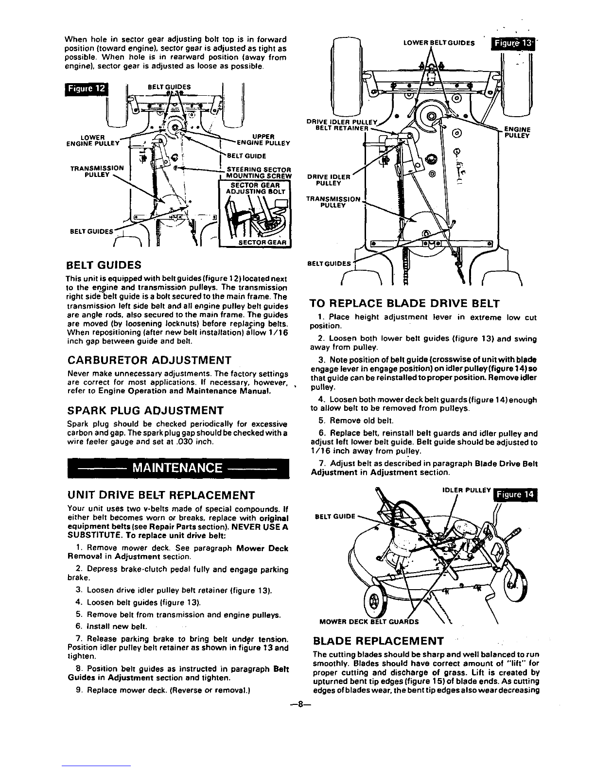
When hole in sector gear adjusting bolt top is in forward
position (toward engine), sector gear is adjusted as tight as
possible. When hole is in rearward position (away from
engine), sector gear is adjusted as loose as possible.
BELT GUIDES
LOWER BELTGUIOES
LOWER UPPER
ENGINE PULLEY EY
DRIVE IDLER PULLEY
BELT RETAINI . ENGINE
PULLEY
TRANSMISSION STEERING SECTOR
MOUNTING SCREW DRIVE IDLER
PULLEY
TRANSMISSION
PULLEY
BELT GUIDES
This unit isequipped with belt guides (figure 12)located next
to the engine and transmission pulleys. The transmission
right side belt guide is a bolt secured to the main frame. The
transmission left side belt and all engine pulley belt guides
are angle rods. also secured to the main frame. The guides
are moved (by loosening Iocknuts) before replacing belts,
When repositioning (after new belt installation) allow 1/16
inch gap between guide and belt.
CARBURETOR ADJUSTMENT
Never make unnecessary adjustments. The factory settings
are correct for most applications. If necessary, however. ,
refer to Engine Operation and Maintenance Manual.
SPARK PLUG ADJUSTMENT
Spark plug should be checked periodically for excessive
carbon and gap, The spark pluggap should be checked with a
wire feeler gauge and set at .030 inch.
BELTGU|O_
TO REPLACE BLADE DRIVE BELT
1. Place height adjustment lever in extreme low cut
position.
2. Loosen both lower belt guides (figure 13) and swing
away from pulley,
3. Note position of belt guide (crosswise of unit with blade
engage lever in engage position) on idler pulley(figure 14)so
that guide can be reinstalled to proper position. Remove idler
pulley.
4. Loosen bothmower deck beltguards(figure14)enough
to allowbelttobe removed from pulleys.
5. Remove old belt.
6. Replace belt, reinstall belt guards and idler pulley and
adjust left lower belt guide. Belt guide should be adjusted to
1/16 inch away from pu!ley.
7. Adjust belt as described in paragraph Blade Drive Belt
Adjustment in Adjustment section.
UNIT DRIVE BELT REPLACEMENT
Your unit uses two v-belts made of special compounds. If
either belt becomes worn or breaks, replace with original
equipment belts (see Repair Parts section). NEVER USE A
SUBSTITUTE. To replace unit drive belt:
I. Remove mower deck. See paragraph Mower Deck
Removal in Adjustment section,
2. Depress brake-clutch pedal fully and engage parking
brake.
IDLER PULLEY_
3, Loosen drive idler pulley belt retainer (figure 13).
4. Loosen belt guides (figure 13).
5. Remove belt from transmission and engine pulleys.
6. Install new belt. MOWER DECK BELT GUARDS
7. Release parking brake to bring belt undgr tension.
Position idler pulley belt retainer as shown in figure 13 and
tighten.
B. Position belt guides as instructed in paragraph Belt
Guides in Adjustment section and tighten.
9, Replace mower deck. (Reverse or removal.)
BLADE REPLACEMENT
The cutting blades should be sharp and well balanced to run
smoothly, Blades should have correct amount of "'lift" for
proper cutting and discharge of grass. Lift is created by
upturned bent tip edges (figure 15) of blade ends. As cutting
edges ofblades wear, the bent tip edges also wear decreasing
--8--

I_la_e lift. resulting in decreased cutting ability. Because of
"this, ,resharpbning of blades will not help much. It is
recommended that blades be replaced•
IMI_ORTANT: Stop engine, remove spark plug end
inspect blades at once if you strike any solid unyielding
object. Check to make sure blade mounting screws are
tight. To remove blades:
1. Remove mower deck (see paragraph Mower Deck
Removal in Adjustment section•
2• With a 9/16 inch wrench, remove blade mounting
screws (figure 15) by turning screws counterclockwise.
When replacing blades, be sure all parts are reassembled in
proper order (see Unit Repair Parts section for proper order)
or severe vibration will occur. Bent tip edges of blades must
be up toward topof mower deck or blades will not cut. NOTE:
Make sure blade mounting screws are tightened securely.,
We recommend a 10 inch wrench or atorque wrench. If
torque wrench is used. torque blade mounting screws to
between 30 and 35 font pounds.
BENT TIP EDGE
QUILL
ASSEMBLY
AIR FILTER MAINTENANCE
The air filter should be cleaned and re-oiled after every 25
hours of operation under normal operating conditions; more
often under dusty conditions, To clean air filter, proceed as
instructed in Engine Operation end Maintenance Manual.
CAUTION A
Never run the engine without the air cleaner element
installed, a defective air cleaner can result in loss of
engine power end can cause excessive wear or
damage to engine components if dirt or dust is
permitted to enter engine through the carburetor. A
damaged air cleaner, orone that isclogged with dust
or dirt should be replaced immediately.
WIRING DIAGRAM
Parts breakdown on page 13 of this manual isdesigned to be
used as a wiring diagram.
We recommend that unless you are fully qualified to make
repairs on the electrical system on this unit, you take it to a
competent repairman for such work or adjustments.
BLADE MOUNTING SCREWS
TO CHANGE CRANKCASE OIL
Crankcase oil should be changed after first 5 hours of
operation and every 25 hours thereafter. See Engine
Operation and Maintenance Manual for proper procedure.
Check oil level before each use. Add oil as required.
1, Place flat bottom 2 quart container beneath oil drain
tube (see figure 16).
2. Remove drain plug end drain oil. NOTE: Oil fill cap
should also be loosened to serve as an air vent.
3. Replace plug. remove oil fill cap and refill crankcase as
outlined in Engine Operatlon-and'Maintenance Manual.
4. Replace oil fill cap•
OIL FILL CAP
OIL DRAIN TUBE
LUBRICATION
Lubricate as shown in Lubrication Chart.
ADANGER A
Never store engine with fuel in tank indoors or in
enclosed, poorly ventilated enclosures, where fuel
fumes may reach an open flame, spark or pilot light
as on a furnace, water heater, clothes dryer, etc.
Handle gasoline carefully. It is highly flammable end
careless use could result in serious fire damage to
• your person and/or property.
The riding mower should be immediately prepared for
storage at the end of the season or if the unit is to be un-used
for 30 days or more.
ENGINE STORAGE
Gasoline, if permitted to stand un-used for extended
periods (30 days or more), may develop gummy deposits
which can adversely affect the engine carburetor end
cause engine malfunction. To avoid this condition,
proceed as follows:
1 Prior to shut down for 30 days or more, drain fuel tank.
2. Run engine until fuel tank is empty end engine stops
due to lack of fuel.
3. Remove spark plug and pour one (1) ounce ofengine oil
through spark plug hole into cylinder. Crank engine several
times to distribute oil. Replace spark plug.
UNIT STORAGE
1. Clean the unit thoroughly.
2. Inspect the riding mower for worn or damaged parts,
tighten all loose hardware.
3. Oil all points shown in Lubrication Chart.
4. Store the riding mower in eprotected area end cover
the unit for additional protection.
A yearly checkup or tuneup by a qualified repairman is agood
way of insuring that your riding mower will provide
maximum performance for the next season.
--9--
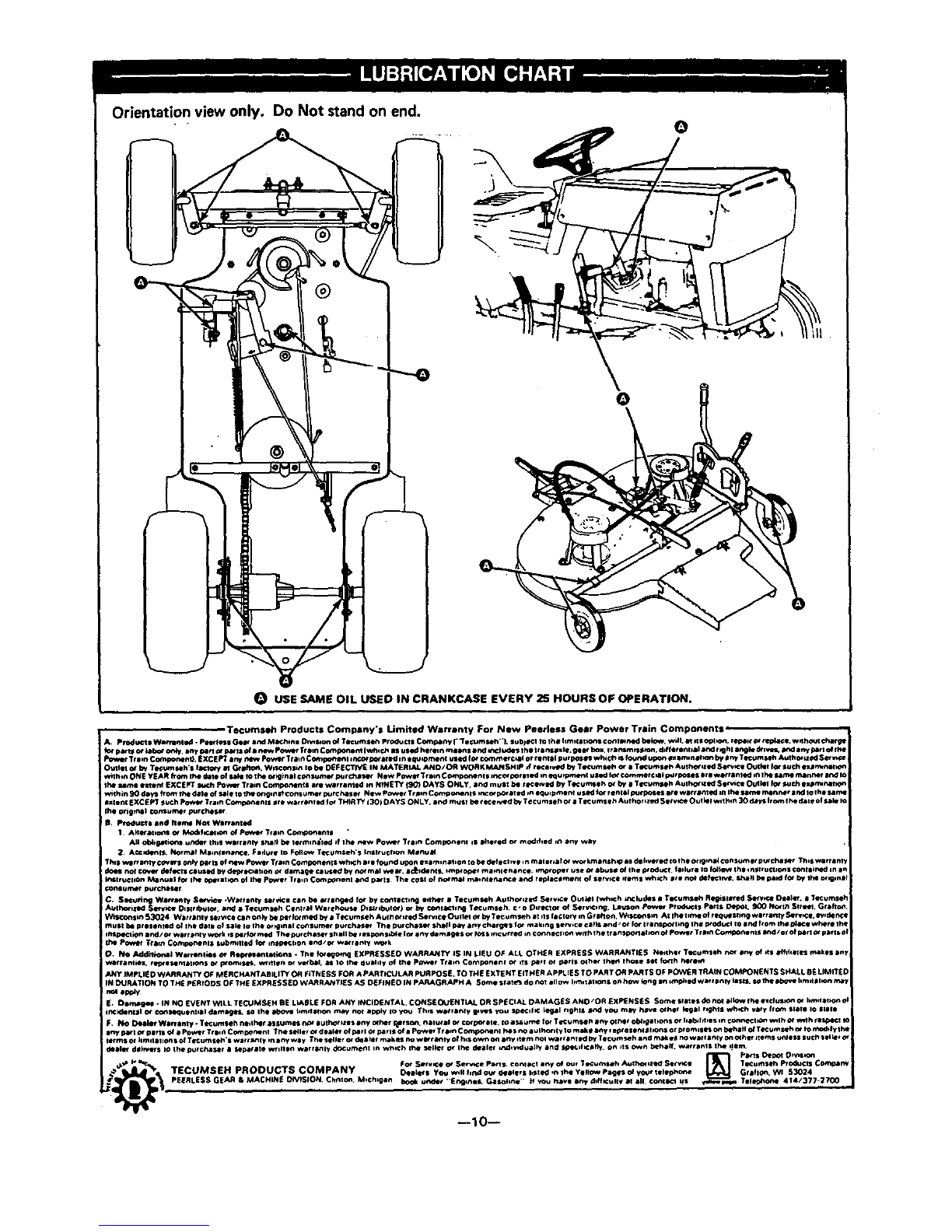
Orientation view only. Do Not standon end. 0
OUSE SAME OIL USED IN CRANKCASE EVERY 25 HOURS OF OPERATION.
, Tecumslh Products Company's Limited Warranty For New Peerless Gear Power Train Components,
A. P_¢luct• Wemlnlld. pW_m Gear and M_chin| Dn_s_on of Tl_cmseh P)-oducl| Coml_ny i"[e_mseh'_, sub)•C11o t he hm_la: _Cc_III_KI bek_, w_l.ltolSOpl_,r_l¢_tl_dace.w_hC_lchargtm
f_" _Or I_b_ otdy, any N rt _, IrMlS _ • Pew P_r Tr•nn C ml_tn_ IwhlcP. 8S uSial herren ms•n | •rKt mc_u_es l he Item.hie. Ile_r box, _rJrmm ;st._on, dJferBnl0•l •rKI r_h181_kl dr .VqlL led •ny N rt of Ihe
Pr*wer _r_m c_m_n4m_ |xcEFr18rr_ _ P_ Tta1n c_m_p_en_ au_e_ed _n_n_ _ f_ _m_r©_ _ r_n_ pur_ whiCh _ _ u_ _nI_ _ D_ T_um_ _N $_
• •hi! _by Te_umseh's f_ MGr iho_. W_s_, K• be DEFECTIVE IN MATERIAL AND/OR WORKMANSHIP Jrwcelved by Tecumsel_ ¢,r •Tecumset_ Author _lSe_:l Outl_l fo_ Such ex_mmmN_
w_lhin ONIE yE_.R _ram the _i_le ol sa_l Io lhe _qlin•l ¢_summ- _t _ N_wP_w_TremC_mp_nent_o_4)r$1_dm_x_u_pm_nIu$_d_c_mm_r¢N_r_r`s-es_rIworr_medm_h1furr4m_nrmt8n_
1he Hme extent EXCEPT _PO_ Tt•in Ccm'_onent s art w•rranl_KI mI_NEI"f fO0) DAYS ONLY. an_ mu$_ be rt_ce_ by T_K.,t_e ho,' by • T_rcurnseh Authored S_C_ Outlel for t.uch •]u_rmt_al_n
w,th_n SO d_, nh-(_m lhe dale of S_l_ to th_ot0gml_consum_r purchaser NOw p_l.q_ Tr•mC_oqent$ _r_or _¢_•_•d _n •qu_pmenl u$_l for ren_•_ I;_rl_X_s are wl_t_ntqd n_ Ihe same m_nPA_r •hal lU the same
•xeenK EXCEPT _bch Pow_ Tra_ Com_._,_nl$ •¢e w_r r•n¢_l for "[HIRTY 130) DAYS ONLY. er, d muST be ¢ece ;veal by "r_¢umseh ot •Tm:umseh Au_hof _zsd S_t¥_-e Oulkfl wd_m _0 days from th_ d_le ol s_le m
i Iho origrn•l _nsumer purch_
!III, P_ucts and hem4 Not Wo_'onted
1 A;ler/*lim_ of It4_d_hr_m of Power "[film C_n#ormnl• •
All obh_mtin urger Ihh• wmrranly sha_ I_ letmln_led _f ihe _A_w power "[t •;n Component _s Idler ecl or modnhed i_ _ny way
;_ A_:_e_e$, NormD_ M•mlln•_¢, Fmdur_f I• FOI_ Tecumseh'$ InStrucfmn Monu_
"rl_ s v*l_anty Cm_lr$ only IHrlS of new pow_ Train Comoonent$ wh)Ch •ro fourKI upon exammJl_on io be _fe¢llve inma_lr_•t of wof km•nsh_ ms dmlr._ered _oCh•or rg_r,l_ ¢_nsumet pu_chJt.er This warr•m
d_es nor C_I_ de_:fl _l_lld by de_r ic_•10on _. dlma_ie r.Jt_S_ by n_'m•l wear. •c_:0dent•. _m_ _er mm_nlenance, irr_roper USe or •buS• 0# the i_ •duct a_dur eto foIk_w th• in_ruClmns con I•_ned an •
I_stru_lhon Mlnual for ihe 0get it _'1 (4 _Pcw_Jr Tram C(m_nenl •_,d Dwl$ The coal of nor m_)l m_t _*P_ln_e er.:l re_l_©emenl of serwc_ ilem$ wh:Ch •_t no€ de_'lw¢, sh•)l bl _1_ rot by lt_ _rlgln_l
ronsum_f purch_lSer
C* S_ng W•mmt_t Se_-_-I -W•rr •nty set w=e ¢•n be _t •n_d _o_ by co_l•¢l_n_l _her • TecumS41h Aulhor_zs, dSet vN:t O_,IMI fwh_:h _nc ludl• •Tlcumslh R_nsl_ed Se_;ce D_•I_, •T_c urns•;"
_lhoti_KI Setv_l D_St r_.¢ul_; and • T•¢umleh CBnlr_)l War•house DnSI_ 01_JIo_) o, by c¢_la_llnfl TeCumseh, ©, o Dit_ct _of Serv_:lng. Lauson p¢_*_l f pt _d_l• P•rl$ Depot. 900 N_;/1 Stt_L Gr•hm_
Wnl¢_n•hr_ 5_024 W•rt•nly serv_c• c_n on )y be pe_lot m_l by • Tec umseh A _11_of _ed Se_*_¢e Ou ilel _ by T ecumS_h •t nl$ r•¢lont on G r•hon, Wl_n •m AI Ihe I _,_1 of r t_u4_sl_n_ w•rren_/Set _¢_, I_rd_ _l:q
must b_ prosent•d of ih• ¢_•_• oP $•_¢ io the of _0nel Coctsumer pu¢cha_ The _urch•sl_ ShMI _ •'y chef.slot making Se_ce ©•f)s and, or |or _r•ns_lmg 1he I_0d_Cl Io •,_d f_om _he _11_ where lh_
ihspe_i_n end/_ w_r r•nly work IS i_t fof m_l The purch•$of •1_•11 be r•$_ons_ble lot •ny d_m_$ or I_$ mc_rr_l i,_¢_ne¢_lon wnlh _he t r•nspOnehO_ o# Power Tr_n Comic•hems Ind/or of p_rl o¢p•rlsoi
dm P_et Tr•m Coml_nenl• submlll•d for ms_g_on •nd/cx wart •_ly w_k
O. NO Addilkmal Wu •n _e• Or R e_m _n• - T_e fo_e_m_l EXPRE$SEO WARRANTY _S IN LIeU O. _ ALl. OTHER EXPRESS WARRANTI£$ Neither l"Kumseh nor •r,y ef ;_• Ifhk•i_ mak•$ av
v_rr•nl_es, rll_•SeP4•t_s of promises+ wtl_l_n or v_l_l_ am IO lhe _u•lnl¥ _4 _h• pm_'er Tr•m Compone_l or _!S parl or _rl$ _4 f',l_ th_ Ih_e •t_ fo_h hece_
ANY IMPLIED WARRANTY OF M_RCHANTAB_LII_ OR fiTNESS FOR APARTICULAR PURPOSE. TO THE EXTENT EITHER APPLIES TO PART OR PARTS OF pOWeR TRAIN COMPONENTS SHALL 0E LIMITS
)N DURATION TO THE p_RIOOS OF THE EXPRESSEO WARRANTIES AS DEFIN£O IN pARAGRAPH A Sore• Stern do not allow I_.'_i _1m_s on how kong •n*mp)_lw•r r•nly la$1_, _th_ •b_ I_m_t_l_n real
;_D_m_ 9e_ -IN NO £VENT WILL TSCUMSI_H 8E LL_I_ LI_ FOA ANY _NCIDENTAL. CONSEQUENT_L OR SP£_IAL DAMAGES ANO/OR £XPENS£_; Som_ •_•t_$ do no_ •_l_w Ih_ e.clus_ _ I_m,l•.on o
i_¢ m_n_l o¢ con_u•n_l•l damages, _ _he _ I_mlt •_on may nof •_¥ io YOU Thrl w_tF_nly _$ you s_ecnl_¢ _egal rlg_l$ •rid you _f h_v_ _I_g•l .ghl$ which v•ry rrom $1•1_ IO •l•le
FN_ I_t_ler W_l_•my Tl_umsehnenlh_r•$sumesP_*•u_ho_ls•nY •4her _s_, n•lU eof c_o_el_. _oessurm_ of Trcumse_•nyocr4r_bll_•t_onsofll•_r_lsm¢orm4_v_mV_lhMWdhrl_*_l_h
•r.ypatlorp•tl$of•pm_r Tr•_Com_mln_ -(_se_er_td••_er_f_r_ofp_r_$of•PGw_Tr•_nC_mp_nen_P_$rm•u_h°r_ty1_make•n¥rmpr•$en_*°n•°r_°m_ses°_beh•_ofT_um_ _tO,'N_k ylh_
I•rm$ Of heal•lions CJ T_cum$•l_'s wl_¢_l_ m•ny w•y The seller Of deek_r m_kes no wle r_niy of h_s _on _ny *tern nol werr•nTId by Te©umseh and make_ no w•rr•nly on o_h_ _tem$ unleSS such SBI;eF Of
de•let d_F_tr$ Io ihe p_r ¢;le_er •sep_r •re WtnllBn w•r rarely documerlt in w_*¢h _he seller or ihe d_•ler md_,_du_l_y and t._l_._ _c• f )y on •Is _n behalf, wet r•nl• _he 0_em,
,_ I* _*_%_ For Service _. Ser_e Perls CO_l•©t eny o/ Our 1_:umseh _lh_ll_ S_V_;t TKurnseh Products Cornel mt
TECUMS EH PR •DUCTS COMPANY _e_'• Y_ w,alf,na ou, _otr• I,_1_ ,noh• V•llow pa_eso_yourIile_,o*_ Gr•hon, W_ S3024
PEERLESS GEAR & MACHINIE ON_51ON C_rnton, M*ch_gan book ut_er "Er_llnef_ G•solln_'" ;_ vo_ have _ny dlff_¢ullv 31 •11, conll¢l us _e_. Tilephone 414/377-_700 ,
--10--

PROBLEM
Mower Cuts
Ragged or
Uneven
Mower Leaves
Unmowed Strip
Between
Blades
CORRECTION
1. Make certain blades are sharp and in good condition (not bent or incorrectly mounted).
2. Check blade mounting bolts. Blade bolts must be tight.
3. Check quill assamblyfs) for damage or bearing wear. Replace if necessary.
4. Remove any accumulation of grass clippings from underside of deck housing.
5, Check for possible damage to mower deck housing. Repair or replace if necessary.
6. Check pivot tube assembly for damage. If bent or damaged, repair or replace.
1,
2.
3.
4,
5.
6.
1,
Mower 2.
Scalps Lawn 3.
Mower Will 1.
Not Discharge 2.
Clippings
Properly 3.
Check for worn or dull blades. Replace if necessary,
Check quill assemblies and make certain none are bent. Replace if necessary.
Mowing a heavy stand of grass or grass with excessive surface moisture could allow mower
to leave a strip unmowed. Mow counterclockwise (side discharge only). Do not mow wet grass,
Forward speed should be adjusted to mowing conditions by gear selection. Engine should be
run at full throttle.
Check blade belt tension. Adjust if necessary.
Check for damage to mower deck housing, Repair or replace if necessary.
Check for bent blade(s) or bent quill assambly(s). Replace if necessary.
Check mower height adjustment setting and readjust if needed, Scalping is more likely on rough or
uneven lawns.
Check deck leveling adjustment setting and readjust if needed.
Check underside of dec_ housing for accumulation of clippings. Remove accumulated clippings.
Wet conditions can cause the discharge chute and underside of deck to become clogged
with clippings. Do not mow wet grass.
If blades have been replaced, make sure they have been correctly mounted.
1. Check belt tension. Adjust if necessary.
2. Check all belt guides. Correct clearance is 1/16 inch from belt when blade engage lever is engaged.
Blade Drive Belt 3. Make certain deck leveling adju6tment is correct. If not, readjust.
Comes Off 4. Check for and remove any foreign objects interfering with belt travel.
During Use 5. Check all pulleys on mower deck. A split or bent pulley could cause problems. Replace if needed.
6. Check engine drive pulley inner surface. If inner surface is rough or split, pulley should be replaced.
7. Check blade throwout assembly for wear. Replace necessary parts,
1. If grass is too high or wet, belt slippage may occur,
Blade Drive Belt 2. Check belt for wear or damage, Replace if necessary.
Slips 3. Check belt tension. Adjust if necessary,
4. Check blade drive belt tension spring. If spring is stretched or damaged, replace spring.
1. Check all belt guides. Correct clearance is 1/16 inch from belt when blade engage lever isengaged.
Blade Drive Belt 2. Check for and remove any foreign objects interfering with belt travel,
Wears Exces- 3. Check pulleys for damage, Replace if necessary,
sively 4, Make certain belt brake is clearing belt when mower is engaged, If brake cable is too long
or broken, adjust or replace.
!5. Make certain mower deck leveling adjustment is correct. Adjust if necessary,
Blade(s) J1. Check be_t. If worn or broken, replace, If belt is too loose, make belt adjustment if necessary.
Will Not i2. Check engagement spring on deck engagement idler, If broken or damaged, replace.
Engage 3. Check for end remove any foreign obje,"._sinterfering with engagement idler travel.
Blade(s) 1. Check belt tension. Adjust if necessary.
Will Not 2. If blade drive belt adjustment will not provide enough slack in drive belt, replace with correct
Disengage original equipment belt,
3. Check for and remove any foreignobjects interfering with engagement idler travel.
1. Check blades and make certain ;hey are not bent, out of balance or loose. Replace if necessary.
Extreme Vi- 2, Check belt for burn spots or irregularities that might contribute to vibration. Replace if necessary.
bration Occurs 3. Cneck quill assemblies for damage or wear. Replace if necessary,
When Blade is 4. Check for worn cr damaged hla,Je engagement parts. Repair or replace as necessary.
Engaged 5, Check engine drive pu!!ey inner s_rface, If inner surface is rough or split, pulley should be replaced.
6, Check underside of deck huus_n3 for accumulation of clippings. Remove accumulated clippings.
7, Check for loose or damaged engir:e mounts. Tighten or replace as necessary,
!Deck or Deck 1. Deck drive belt adjustment is tr)o tight. Readjust.
iWheel Hits Rear 2. O'.her than original equipment belt is being used and is either too long or stretched. Replace belt.
, Wheel and Tire 3. Belt is worn, Replace with new o._;ginetequipment belt.
iAssembly 4. Check pivot tube assembly for damage, R':Dair or replace if necessary.
--1 1--

DeckLift
CableBroken
UnitDriveBelt
Slips
Unit Drive Belt
Squeals When
3rake is Applied
Unit Drive Belt
Comes Off
During Use
Unit Will Not
Propel Itself
When CWtch or
Vari-Speed
Lever is
Engaged
Extreme Vi-
bration Occurs
When Clutch is
Engaged
(Let-Out)
Unit Will Not
Shift or Shifts
Hard
Steering Slips
or is Loose
Engine Will No1
Turn Over
Engine Turns
Over But Will
Not Start
CORRECTION
1. Check operating procedure. Excessive ground speed on rough lawn may cause deck bounce, resulting
in lift cable failure.
2. Remove excessive clippings from under deck housing (build up of clippings adds excessive weight
to deck).
1. Check unit drive belt adjustment(s). Adjust if necessary.
2. Check for damaged or broken clutching idler spring. Replace if necessary,
3. Check belt(s) for wear or damage. Replace if necessary.
4. Check vari-apeed control lever adjustment.
5. Check for and remove any foreign objects obstructing vari-speed or clutching idler mechanisms,
1.
2.
3.
4.
1.
2.
3.
4.
Check brake-clutch synchronization (does not apply to vsri-speed units). Adjust if necessary.
Check unit drive belt adjustment(s). Adjust if necessary.
Check for and remove any foreign objects obstructing vari-speed or clutching idler mechanisim.
Check brake adjustment.
Check belt tension. Adjust if necessary.
Check belt guides. Adjust if necessary.
Check for split or damaged pulleyS. Replace if necessary.
Check clutching idler pulley alignment. If out of alignment, idler bracket may be bent. Replace if
necessary,
1. See steps 1 through 5 in Unit Drive Belt Blips section above,
2, Check engine, transmission or trensaxle pulleys for sheared or missing key, Replace if necessary,
3. Check transmission or transsxle to make certain it is operable. Make certain chain (chain drive units
only) is intact,
1. Check for split or damaged'pulleys. Replace if necessary.
2. Check belt for irregularities or burned spots. Replace if necessary.
3. Make certain belt tension is correct. Adjust if necessary.
4. Check clutching idler assembly for wear or damage. Replace part as necessary.
5. On chain drive units, check sprockets for proper alignment and chain for damage. Replace if necessary.
6. Check for loose or damaged engine mounts. Tighten or replace as necessary.
1. Check shifting procedure. Unit must come to a complete stop before shifting. On vari-speed units,
hold firm pressure on shift lever while moving vari-speed control lever slowly forward.
2. Check brake-clutch synchronization (does not apply to vari-speed units). Adjust if necessary.
3. Check unit drive belt adjustment. Adjust if necessary.
4. Have transaxle or transmission checked by acompetent repairman.
1. Check for steering sector gear and pinion looseness. If gears are loose, make sector gear adjustment.
2. Check ball joints for wear. Replace if necessary.
3. Check center pivot bolt on front axle. If loose, tighten securely.
1. Check starting procedure. Make sure starting instructions are followed.
2. Check fuse (if so equipped).
3. Ch_ck battery for charge. Make sure battery has been activated (on new unit).
4. On new units, remove spark plug and check cylinder for accumulation of oil due to handling.
5. Make visual check of electrical wiring system to make sure all connections end lockout switches
are secure.
6. Check engine according to engine manufacturers instructions.
7. Have electrical system checked by a competent repairman.
1. Check starting procedure. Make sure starting instructions are followed.
2. Make certain tank is filled with clean, fresh, unleaded or low-lead gasoline.
3. Make certain fuel shut-off is open (if so equipped).
4. Make certain throttle is in choke or fast position.
5. Check engine according to engine manufacturers instructions.
6. On recoil start unit, make visual check of wiring system to make sure all connections and lockout
switches are secure.
7. Have wiring and lockout switches (on recoil start unit) checked by a competent repairman,
i ilrr
--12--
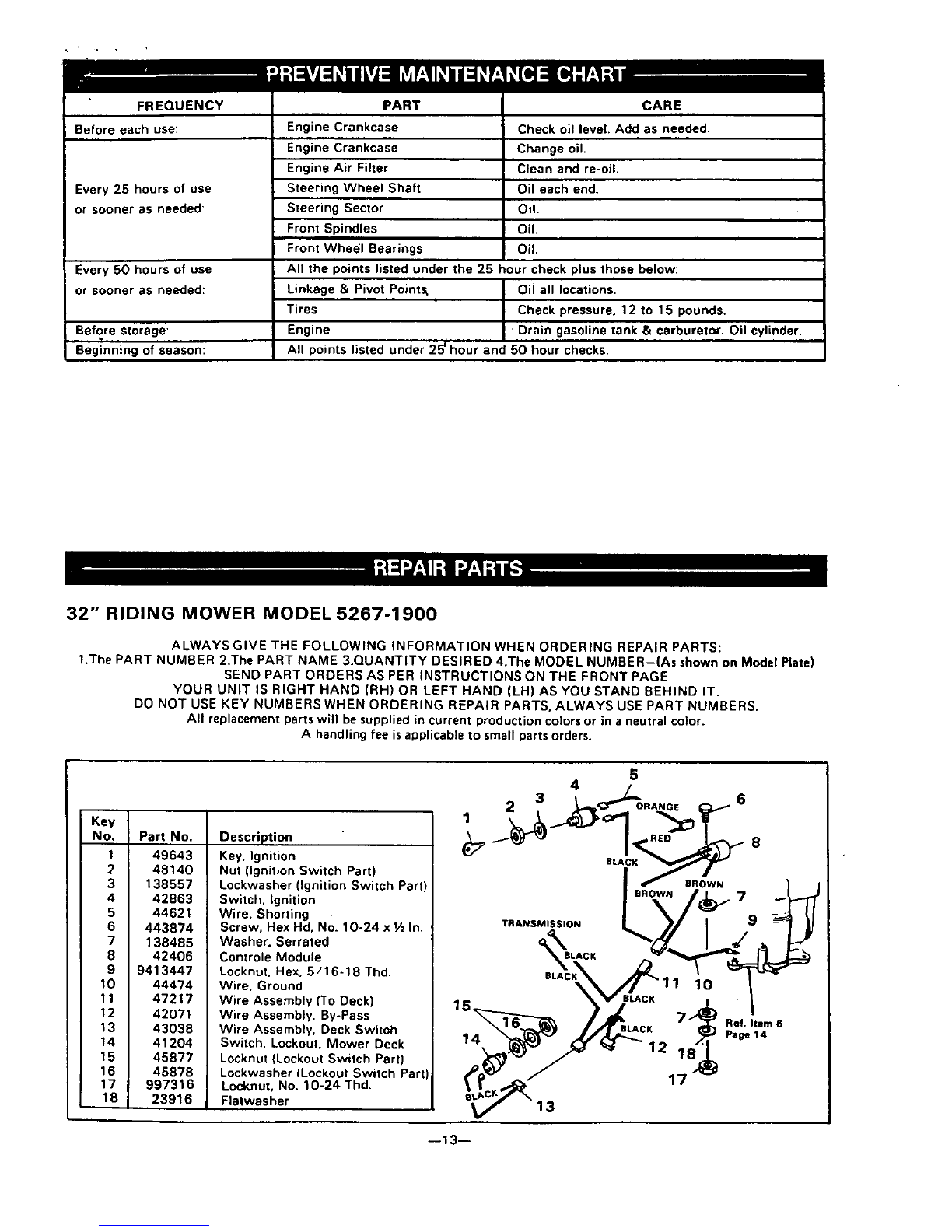
FREQUENCY
Before each use:
Every 25 hours of use
or sooner as needed:
Every 50 hours of use
or sooner as needed:
Before storage:
Beginning of season:
PART
Engine Crankcase
Engine Crankcase
Engine Air Filter
Steering Wheel Shaft
Steering Sector
Front Spindles
Front Wheel Bearings
CARE
Check oil level. Add as needed.
Change oil.
Clean and re-oiL
Oil each end.
Oil.
Oil.
Oil.
All the points listed under the 25 hour check plus those below:
Linkage & Pivot Points. Oil all locations.
Tires Check pressure, 12 to 15 pounds.
Engine ' Drain gasoline tank & carburetor. Oil cylinder.
All points listed under 25uhour and 50 hour checks.
32" RIDING MOWER MODEL 5267-1900
ALWAYS GIVE THE FOLLOWING INFORMATION WHEN ORDERING REPAIR PARTS:
1.The PART NUMBER 2.The PART NAME 3.QUANTITY DESIRED 4.The MODEL NUMBER-(As shown on Model Plate)
SEND PART ORDERS AS PER INSTRUCTIONS ON THE FRONT PAGE
YOUR UNIT IS RIGHT HAND (RH) OR LEFT HAND (LH) AS YOU STAND BEHIND IT.
DO NOT USE KEY NUMBERS WHEN ORDERING REPAIR PARTS, ALWAYS USE PART NUMBERS.
All replacement parts will be supplied in current production colors or in aneutral color.
A handling fee isapplicable to small parts orders.
Key
No. Pa_ No.
149643
2 4814O
3138557
4 42863
5 44621
6 443874
7 138485
8 42406
9 9413447
10 44474
11 47217
12 42071
13 43038
14 41204
15 45877
16 45878
17 997316
18 23916
Description
Key. Ignition
Nut (Ignition Switch Part)
Lockwasher (Ignition Switch Part)
Switch, Ignition
Wire. Shorting
Screw, Hex Hd, No. 10-24 x1/zIn.
Washer, Serrated
Controle Module
Locknut. Hex, 5/16-18 Thd.
Wire. Ground
Wire Assembly (To Deck)
Wire Assembly. By-Pass
Wire Assembly. Deck Switoh
Switch. Lockout. Mower Deck
Locknut (Lockout Switch Part)
Lockwasher tLockout Switch Part
Locknut, No. 10-24 Thd.
Flatwasher
14
5
4
TRANSMISSION
BLACK
BROWN
11 10
1"7
7
9
Ref. Item 6
Page 14
--13--

32" RIDING MOWER MODEL 5267-1900
I"
7 8 35
49 .--4
41-_'_-4L. 4.3,
Ref. Item 38
51
52
64 63
\\
ALL UNNUM8E RED
ITEMS ARE INTERCHANGEABLE
WITH OPPOSITE SIDE

32" RIDING MOWER MODEL 5267-1900
I
Key
No.
1
2
3
4
5
6
7
8
9
10
11
12
13
14
15
16
17
Part No.
997316
41652
23916
9413447
120638
Engine
46853
23700
9413534
39628
39830
24167
40677
46836
122040
50653
49896
18 271184
19 120386
20 33200
21 120758
22 120382
23 43961
24 39659
25 35374
26 120918'
Description
Locknut, No. 10-24 Thd.
Clip, Conduit
Washer
Locknut. Hex, 5/16-18 Thd
*Lockwasher, Split. 5/16 In.
§See footnote below
Oil Drain Tube
Pipe Plug, 1AIn.
Locknut, Hex, %-16 Thd
Key, 3/16 x 3/6 x 21/z in.
Tire
Valve Stem
*Flatwasher, _,_In.
Support, Bearing Bracket
Screw. Hex Hd, 5/16-16 x 1½In,
Belt Guide, Blade Drive
Belt Guide, Transmission Drive
Belt
Nut. Hex, Keps. 5/16-18 Thd
*Flatwasher, tA In. "
Key, Engine Pulley
Screw, Hex Hd. _-24 x_= In.
Lockwasher, Split
Pulley. Engine
Belt Retainer
Pulley, Idler
"Screw, Hex Hd, _-16 x1½ In.
Key
No.
27
28
29
3O
31
32
33
34
35
36
37
38
39
40
41
42
43
44
45
46
47
48
49
50
51
52
Pa_ No.
28928
46848
43953
22053
43979
39266
3021
49276
121222
120385
43980
52707
52317
52316
43967
43968
40974
69191
50562
52640
48761
43956
42860
rransmission
53102
20307
Description
Shoulder Bolt
Arm, Drive Idler
Spacer
Retaining Ring
V-Belt, Transmission Drive
Pulley, Transmission
Woodruff Key
Spring, Main Drive
*Pin, Cotter, 3/32 x _i In.
Flatwasher
Rod. Clutch
Main Frame
Foot Pad, Left
Foot Pad, Right
Arm, Parking Brake
Spring, Parking Brake
Shoulder Bolt, Parking Brake
Decal, Parking Brake
Spring, Clutch Pedal
Brake Pedal Assembly
Rubber Pad, Brake Pedal
Shaft. Brake-Clutch Pedal
Knob, Gear Shift
:_FOote,Model No. 35-41
Chain Assembly
Link (Only), Chain Connector
No. 41
Key
No.
53
54
55
56
57
58
59
60
61
62
63
64
65
66
67
68
69
70
71
72
73
74
75
76
"Standard Hardware Items - May Be Purchased Locally.
tContact Tecumseh/Peerless authorized service dealer for parts and warranty.
:_Contact J.B. Foote Foundry Co., Fredericktown, Ohio 43019, (614) 694-2055 for parts and warranty.
§Replacement engines and parts are obtainable from Engine Manufacturer's authorized Service Stations who are also to be contacted
in regard to the Engine Warranty. See your Engine Manual for location of these stations.
Pa_ No.
446363
122089
43991
83103
52398
9424215
35410
138485
120229
998013
40394
36625
42815
49053
642
44449
43987
35345
39797
Differenlial
-67327
443874
47974
Description
*Flatwasher, 5/16 In.
*Screw, Hex Hd. 5/16-18 x 3 In.
Belt Guide, Transmission Pulley
Rod, Brake
Bracket, Brake Rod
Locknut, 1A-20 Thd.
Spring. Brake Return
*Washer. Shakeproof, 5/16 In.
Screw. hex Hd, 5/16-18 x VaIn.
*Carriage Bolt, 5/16-18 x 3,4In.
Hub Cap
"'E'" Ring, 3AIn.
Flatwasher
Wheel
Flatwasher
Spacer
Plate, Bearing Retainer
Bearing
Sprocket, 54 Tooth, No. 41
tPeerless. Model 171B
Differential Parts
Decal, Caution 10-24 x Vz In!
Screw, hex Hd, No.
Shoulder Bolt

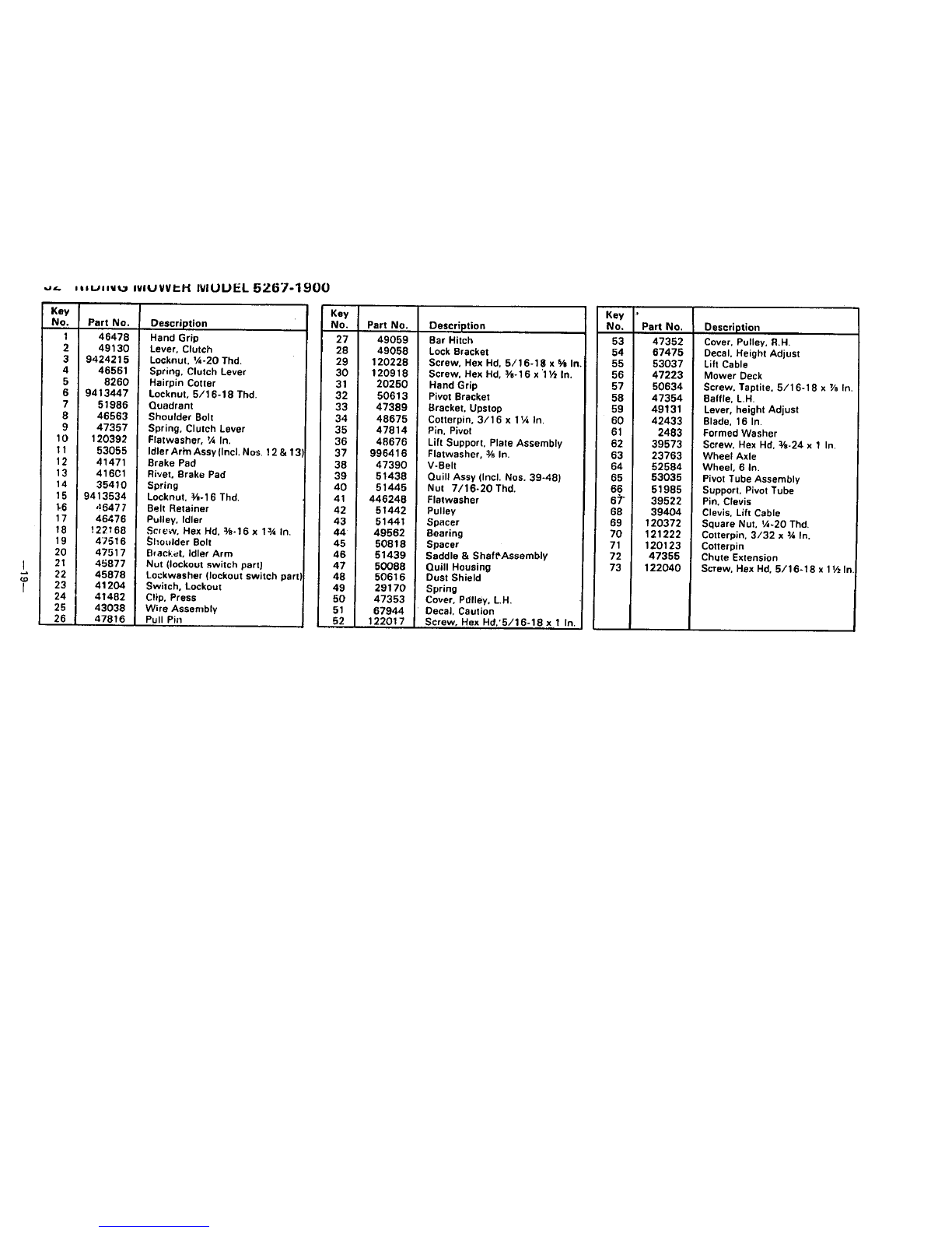
32" RIDING MOWER MODEL 5267-1900
I
d
o_
I 57
16,
50-,_
47
67
30
4)_ 48
3
55 r" 39
59 2
60"
Ref. Item 38
Page 14
69
"37
67
45
17
-26
38- /
3 27
16
Ref. Item 38
Page 14
II

._,_ rt=uJi_ NIOWER MODEL 5267-1900
)
Key
No. Part No.
1 995346
2120228
342815
4 50559
5 46491
6 9413447
7 62857
8121887
946490
10 120386
11 43970
12 122040
13 446363
14 122017
15 46719
16 9424215
17 35287
18 45608
19 39486
20 47083
21 456836
22 39432
23 44012
24 46905
Description
"Screw. Taptite, 1A-20 x½In,
*Screw. Hex Hd, 5/16-18 x % In.
Washer
Screw. hex Hd, 1A-20 xV2In.
Clip. Pin Latch
Locknut, 5/16-18 Thd.
Seat
Screw, Hex Hd, 1A-20 x3_ In.
Pin, Latch
Flatwasher, 5/16 In. I.D.
Fender
"Screw, Hex Hd. 5/16-18 x 1½In
"Flatwasher, 5/16 In.
"Screw. Hex Hd. 5/16-18 x 1In.
Console Assembly
Locknut, Hex. IA-20 Th_
Screw, Taptite. No. 8-32 x % In.
Edging, Hood
Knob. Throttle Control Lever
Steering Wheel
Roll Pin
Bearing. Steering
Dash Assembly
Lever. Throttle Control
"Standard Hardware Items - May Be Purchased Locall
Key
No.
25
26
27
28
29
3O
31
32
33
34
35
36
37
38
39
40
41
42
43
44
45
46
47
48
Part No.
39492
44008
44009
454565
39580
36625
49776
50646
39573
2483
44010
44011
120369
120382
44059
44060
124925
21275
40394
48764
52776
47974
120393
46946
Description
Retaining Ring
Shaft, Steering
Pinion Gear
Roll Pin
Bearing, Steering
"'E'" Ring
Bracket, Deck Guide
Bracket. Deck Guide Support
Screw, Hex Hd Lock. %-24 x 2 In.
Spring Washer
Sector Gear
Shoulder Bolt. Sector Gear
"Nut, Hex. %-24 Thd,
*Lockwasher. Split. YeIn.
Drag Link Assembly
Drag Link
Nut, Hex, %.24 Thd
Ball Joint
Hub Cap
Tie Rod
Hood
Shoulder Bolt
Washer, 5/16 In. I.D.
Wheel & Tire Assy.
Key
No.
49
50
51
52
53
54
55
56
57
58
59
60
61
62
63
64
55
56
67
68
69
PaN No.
49305
49999
120638
49041
9413534
49040
274517
47830
68644
120385
271190
29616
45892
49447
50546
44062
43988
274654
642
49304
4878"2
Description
Spindle, Left
Grille
Lockwasher, Split. 5/16 In. I.D.
Bracket. Grille Support. LH.
Locknut. %-16 7hd.
Bracket. Grille Support. R.H
'Flatwasher. %In,
Bracket. Deck Hanger
Decal, Hanger
Washer, _AIn. I.D.
Nut. Keps. %-16 Thd.
Shoulder Bolt. Axle Pivot
Carriage Bolt. %-16 x 1½ In.
Arm. Steering
Bearing, Spindle
Front Axle Assembly
Bracket. Front Axle Support
Locknut. Hex, _A-20 Thd.
Flatwasher
Spindle. Right
Tie Rod Assembly

32" RIDING MOWER MODEL 5267-1900
I
ALL UNNUMBERED
I_ _ /I
29 31
"" 6 49 73
72
_-.,, lllull_u tVlUVt/I::H IVIUUEL 5Z67-1900
L
T
Key
No.
1
2
3
4
6
6
7
8
9
10
11
12
13
14
15
1.6
17
18
19
20
21
22
23
24
25
26
Part No.
46478
49130
9424215
46561
8260
9413447
51986
46563
47357
120392
53055
41471
416C1
35410
9413534
46477
46476
!22168
47516
47517
45877
45878
41204
41482
43038
47816
Description
Hand Grip
Lever, Clutch
Locknut. 1A.20 Thd.
Spring. Clutch Lever
Hairpin Cotter
Locknut, 5/16-18 Thd.
Quadrant
Shoulder Bolt
Spring, Clutch Lever
Flatwasher, _AIn.
Idler Artn Assy (Incl. Nos 12 & 13
Brake Pad
Rivet, Brake Pad
Spring
Locknut. _-16 Thd.
Belt Retainer
Pulley. idler
Screw. Hex Hd. ¥B-16 xlZA In.
_;ho_dder Bolt
Btack_t, Idler Arm
Nut (lockout switch part)
Lockwasher (lockout switch part)
Switch, Lockout
Clip. Press
Wire Assembly
Pull Pin
Key
No. Pert No.
27 49059
28 49058
29 120228
30 120918
31 20250
32 50613
33 47389
34 48675
35 47814
36 48676
37 996416
38 47390
39 51438
40 51445
41 446248
42 51442
43 51441
44 49562
45 50818
46 51439
47 50088
48 50616
49 29170
50 47353
51 67944
62 122017
Description
Bar Hitch
Lock Bracket
Screw, Hex Hd. 5/16-18 x % In.
Screw. Hex Hd, ¥J-16 x'11/2In.
Hand Grip
Pivot Bracket
Bracket. Upstop
Cottarpin, 3/16 x 1T,4In.
Pin. Pivot
Lift Support. Plate Assembly
Fletwasher, YBIn.
V-Belt
Quill Assy (Incl. Nos. 39-48)
Nut 7/16-20 Thd.
Fletwasher
Pulley
Spacer
Bearing
Spacer
Saddle & ShafPAssembly
Quill Housing
Dust Shield
Spring
Cover, Pdlley. L,H,
Decal, Caution
Screw, Hex Hd/5/16-18 x 1In.
Key
No,
53
54
55
56
57
58
59
60
61
62
63
64
65
66
6_-
68
69
70
71
72
73
Part No,
47352
67475
63037
47223
50634
47354
49131
42433
2483
39573
23763
62584
53035
51985
39522
39404
120372
121222
120123
47355
122040
Description
Cover. Pulley. R.H,
Decal. Height Adjust
Lift Cable
Mower Deck
Screw. Taptite, 5/16-18 x 7/eIn.
Baffle, L.H.
Lever, height Adjust
Blade, 16 In
Formed Washer
Screw, Hex Hd. ¥s-24 x 1 In.
Wheel Axle
Wheel, 6 In.
Pivot Tube Assembly
Support. Pivot Tube
Pin. Clevis
Clevis. Lift Cable
Square Nut. _A-20 Thd,
Cotterpln. 3/32 x 3AIn.
Cotterpin
Chute Extension
Screw. Hex Hd. 5/16-18 x 11/2In
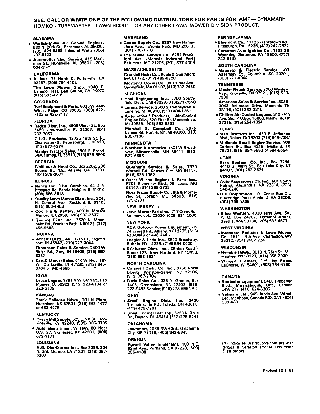
SEE, CALL OR WRITE ONE OF THE FOLLOWING DISTRIBUTORS FOR PARTS FOR: AMF -- DYNAMARI'_ .
HOMKO - TURFMASTER - LAWN SCOUT - OR ANY OTHER LAWN MOWER DIVISION PRODUCT.
ALABAMA
_* Warli¢k-Miller Air Cooled Engines,
630 N. 20th St., Bessemer, AL 35020.
1205) 424-8288. Inbound Watts (800)
292-8123
e Automotive Elec. Service, 415 Meri-
dian St.. Huntsville, AL 35801, (205)
534-3525
CALIFORNIA
*Sillious, 75 North D. Portarville, CA
93257, (209) 784-4102
The Lawn Mower Shop, 1340 El
Camino Real. San Carlos. CA 94070
(415) 593-4716
COLORADO
Turf Equipment & parts, 8035 W.44th
Wheat Ridge, CO 80033. (303) 422-
7123 or 422-7117
FLORIDA
*Redco Distr. Inc., 4909 Victor St., Box
5459. Jacksonville. FL 32207, (904)
733-7957
G.LO. Products, 13735-491h St. N..
Clearwater (St. Petersburg), FL 33520,
(813) 577-4374
Manley Tractor Sales, 5901 E. Broad-
way, Tamp_, FL 33619. (813) 626-5900
GEORGIA•
Walthour & Hood Co., Box 2202. 206
Rogers St: N.E.. Atlanta GA 30301.
(404) 378-2571
ILLINOIS
*Nehl's Inc, DBA Gambles. 4414 N.
Prospect Rd. Peoria Heights. IL 61614,
(309) 685-3613
*Quality Lawn Mower Distr, Inc.. 2245
N. Central Ave., Rockford, IL 61103
(815) 963-4403
* Cox Tire & Blttery. 603-N. Mark_st.
Marion, IL 62959, (618) 993-2607
Garmoe Distr. Inc.; 2620 N. Mann-
heim Rd., Franklill Psr_, L 60131.(312)
455-9588
INDIANA
*Azbell's Distr., 44 - 17th St., Logans-
port. IN 46947. (219) 722-3044
Thompson Sales _Service, 2400 W.
Ridge Rd., Gary. IN 46408. (219) 980-
3282
*Kart & Mower Sales, 616 W. Hwy. 131
W.. Clarksville, IN 47130, (812) 945-
3704 or 945-4555 - "
IOWA
Bruce Engine, 1791 N.W. 86th St., Des
Moines. IA 50322. (515) 223-6134 or
223-6135
KANSAS
Frank Colleday Hdwe., 201 N. Plum.
Hutchison. KS 67501. (316) 663-4477
or 663.4478
KENTUCKY
*Cayce Mill Supply. 505 E. 1st St., Hop-
kinsville. KY 42240. (502) 866-3335
*Auto'Electric Inc.. W. Hwy. 80, Near
U.S. 27. Somerset. KY 42501. (606)
679-1171
LOUISIANA
H.G. Distributors Inc., Box 3388. 204
N. 3rd. Monroe, LA 71201. (318) 387-
6200
MARYLAND
*Center Supply Co., 6867 Hew Hamp-
shire Ave., Takoma Park. MD 20012,
(301) 270-1690
_*The Kunkel Service Co.. 6252 Frank-
ford Ave. (Moravia Industral Park)
Baltimore, MD 21206. (301) 377-4008
MASSACHUSETTS
Crandell Hicks Co., Route 9.Southboro
MA 01772. (617) 485-6300
Morlon B. Collins Co., 300 Birnie Ave..
Springfield, MAO1107,(413)732-7449
MICHIGAN
*Heat Engiqsoring Inc., 7700 South-
field, Detroit, M148228,(313)271-7550
*Lorenz Service, 2500 S. Pennsylvania.
Lansing, MI 48910, (517) 484-1361
_*Automotive JProducts, Air.Cooled
Engine Div., 520 First St. Menominee,
MI 49858, (90,6) 863-6332
Marshall E. Campbell Co., 2975
Lapeer Rd, Port Huron. M148060. (313)
985-7106
MINNESOTA
*Northem Automot_e, 1401W.Broad-
way. Minneapolis, MN 55411.(612)
522-6656
MISSOURI
Gunther's Service & Sales, 7320
Wornall Rd., Kansas City. Me 64114.
(816_ 523-1952
*Oscar Wilson Engines & Parts Inc.,
8701 Riverview BIvd., St. Louis. MO
63147. (314) 368-3333
Ross Frazer Supply Co.. 8th & Monte-
rey. St. Joseph, MO 64503. (816)
279-2731
NEW JERSEY •
•m.Lawn MowerPartslnc.,717CreekRd.,
BeIlmawr. NJ 08030. (609) 931-2006
NEW YORK
ACA Outdoor Power Equipment, 72-
74 Everett Rd., Albany. NY 12205, (518)
438-0440 or 438-4444
Loegler & Ladd Inc., 3940 Broadway.
Buffalo, NY 14225, (716) 684-0600
•*Stiefvster Distr. Inc., Clinton Road -
Route 12B, New Hartford. NY 13413,
(315) 853-5581
NORTH CAROLINA
*Carswell Distr. Co. Inc., 3750 North
Liberty. Winston-Salem, NC 27105,
(919) 767-7700
Dixie Sales Co., 335 N. Greene. Box
1408. Greensboro, NC 27402. (919)
273-9483 Service; (919) 273-5964 Pts.
OHIO"
* Small Engine Distr. Inc., 2430
Tremsinsville Rd., Toledo, OH 43613,
(419) 475-7261
Small Engine Distr. Inc., 5250 N. Dixie
Dr., Dayton, OH 45414, (513) 278-8241
OKLAHOMA
Lawnmart, 1039 NW 63rd.. Oklahoma
City, OK 73116, (405) 842-8845
OREGON
Ppwell Valley Implement, 103 N.E.
92nd Ave.. Portland, OR 97220. (503)
255-4188
PENNSYLVANIA
* Bluemont Co., 11125 Frankstown Rd..
Pittsburgh, PA 15235. (412)242-2522
*Scranton Auto Ignition Co., 1133-35
Wyoming. Scranton. PA 18500, (717)
342-8133
SOUTH CAROLINA
*Magneto 8z Electric Service, 103
Assembly St., Columbia. SC 29201.
(803) 771.4044
TENNESSEE
*Master Repair Service. 2000 Western
Ave.. Knoxville, TN 37921, (615) 523-
7930
American Sales &Service Inc.. 3035-
3043 Bellbrook Drive, Memphis TN
38116, (901) 332-2210
e Chilton Air-Cooled Engines. 319 - 4th
Ave. So.. P.O.Box 15806. Hsshville, TN
37215, (615) 254-1634
TEXAS
*Marr Brothers Inc., 423 E. Jefferson
Blvd.,Dallas, TX 75203. (214) 948-7387
*Midlands Small Engine Service, 106
Carlton St., Box 4215. Midland. TX
79701. (915) 684-5553 or 684-5554
UTAH
Stan Bonham Co. Inc., Box 7246.
4410 S. Main St., Salt Lake City. UT
84107. (801) 262-2574
VIRGINIA
*Auto Accessories Co. Inc.. 601 South
Patrick. Alexandria, VA 22314. (703)
548-0240
*RBI Corporation, 101 Cedar Run Dr.,
(Lakeridge Park) Ashland. VA 23005.
(804) 798-1535
WASHINGTON
*Bitco Weetemo 4030 First Ave. So.,
P. _. Box 24707. Terminal Annex.
Seattle. WA 98134. (206) 682-4677
WEST VIRGINIA
Interstate Radiator 8= Lawn Mower
Co., 1611 -4th Ave., Charleston. WV
25312. (304) 345-1724
WISCONSIN
*Reliable Hdwe., 8010 N. 76th St.. Mil-
waukee, WI 53223, {414) 355-2900
*Wiggert Brothers, 325 Jay StreeL
LaCrosse. WI 54601. (606) 784-4790
CANADA
.Suntester Equipment, 6466 Timberlea
Blvd., Mississsuqua. Ont., Canada
L4W 2T7, (416) 624-6200
.Yetmans Ltd., 949 Jarvis Ave. Winni-
peg. Manitoba. Canada R2X 0A1. (204)
589-4391
(e) Indicates Distributors that are also
Briggs & Strstton and/or Tecumseh
Distributors.
Revised 10-1-81
Popular Lawn Mower manuals by other brands

Country Clipper
Country Clipper JAZee One SR100 Safety instructions & operator's manual

Kubota
Kubota ZG124E-AU Operator's manual

Kubota
Kubota Z232KW-AU Operator's manual

Husqvarna
Husqvarna Z 572x user manual

Snapper
Snapper Z-rider Set-up instructions & pre-operation checklist

AL-KO
AL-KO 660 Original instructions for use


