Teradici TERA2240 User manual
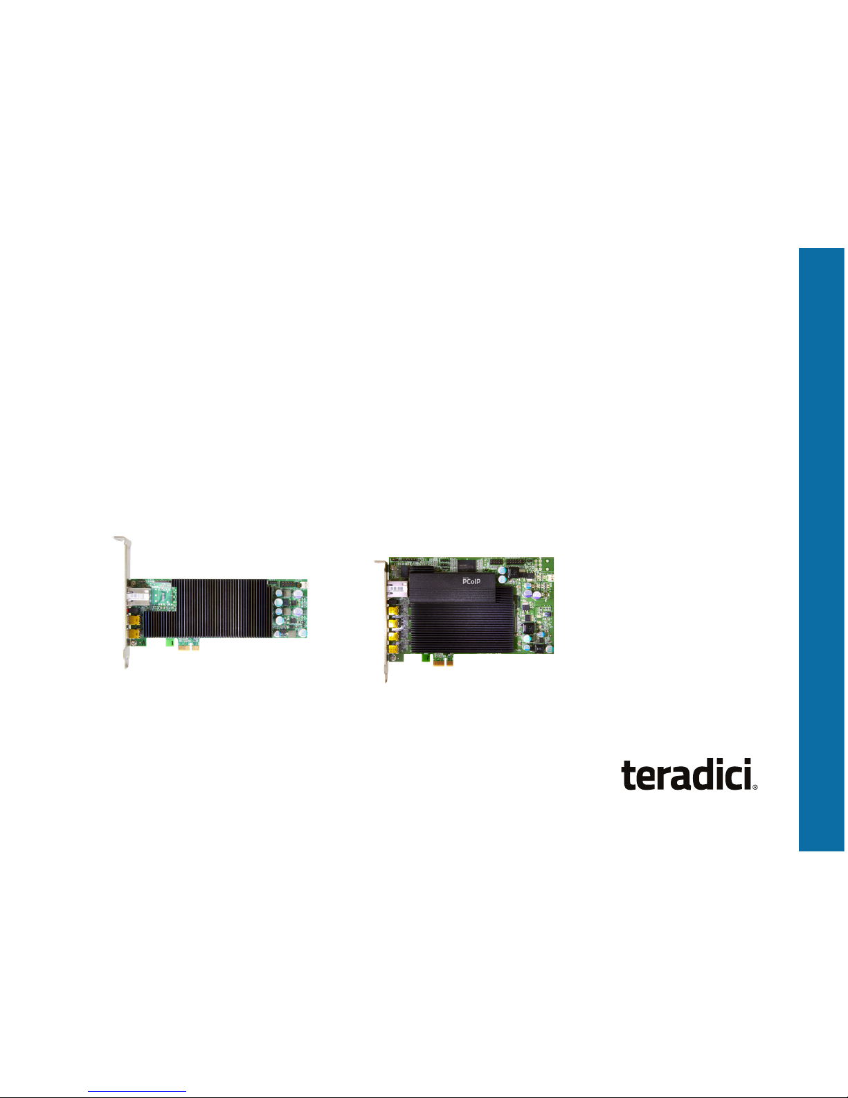
Models: TERA2220 Dual Display
TERA2240 Quad Display
Actual products may not be exactly as shown.
TERADICI PCOIP®
REMOTE WORKSTATION CARD
Quick Start Guide

3
PACKAGE CONTENTS
The package contents include:
• Teradici PCoIP Remote Workstation Card
• Teradici PCoIP Remote Workstation Card power
button cable
• Mini DisplayPort to DisplayPort cables
• Mini DisplayPort to single-link DVI cables
• Teradici PCoIP Remote Workstation Card
Quick Start Guide (this document)
SYSTEM REQUIREMENTS
•PCI Express x1 compatible card slot (Full Height,
Half Length for TERA2240, Low Profile
for TERA2220)
•Host PC with 1 or 2 graphics cards
•For 2560x1600 resolution, graphics card must
contain DisplayPort ports
•PCoIP-compatible client endpoint (see
specifications table)
•Windows XP installations must use the Realtek
High Definition Audio Codecs software from
www.realtek.com (Downloads). Linux installations
must use the alsa-driver package from
www.alsa-project.org (Downloads).
For more information, see KB 1577 on the
Teradici Support Site.
Thank you for purchasing
the Teradici PCoIP Remote
Workstation Card. This card
provides a rich computing
experience with delivery of up to
60 frames per second. It allows
users to access their workstation
from wherever they happen to
be—in a conference room at the
office, at home, or on the go.
This guide will help you install
and configure your PCoIP Remote
Workstation Card and connect
from either the PCoIP Software
Client or PCoIP Zero Client.

4
a. Connect the white end of the workstation card power button cable to
the power button cable connector on the workstation card.
b. Locate where the host PC front-panel power button cable connects
to the motherboard. Disconnect the host PC’s front-panel On/Off
switch cable from the motherboard’s header, and locate the Power
On/Off signal pins. Connect the red wire on the workstation card
power button cable to the positive terminal of the Power On/Off
pin. Connect the black wire to the negative terminal. The negative
terminal is typically a ground pin. NOTE: The location of the Power
On/Off switch pins is different from one motherboard to another. See
your motherboard user manual for details.
c. If possible, connect the host PC’s front-panel On/Off switch cable to
the 2-pin header on the workstation card power button cable. If this
is not possible, the host PC’s front-panel On/Off Switch is disabled.
INSTALLATION STEPS
Setting up the PCoIP Remote Workstation Card
NOTE: The workstation card’s MAC address is located on a sticker on
the card. It is important to write down this address before installing the
card in the host PC. You will need it to connect to the card using SLP host
discovery.
1. Ensure the host PC is turned off and unplug the power cables.
WARNING: Always power down and disconnect devices from
AC power before handling them. Failure to do this can result in
personal injury or equipment damage. Some circuitry on the host
PC can continue to operate even though the front panel power
switch is off.
2. Remove the chassis cover and locate an available PCIe slot.
3. Remove the expansion slot cover of the appropriate PCIe slot for the
PCoIP Remote Workstation Card.
4. Insert the PCoIP Remote Workstation Card into the PCIe slot and
secure the metal bracket.
5. Install the PCoIP Remote Workstation Card power button cable.
This optional connection allows a remote user to reset the host PC
(e.g., when the operating system is non-responsive). The following
illustration shows an example of connecting a workstation card and
remote power cable.
B
C
A
Host Card
Host PC Motherboard
Front Panel
Switch

5
6. Connect the workstation card to your network using the Ethernet port.
7. Using the appropriate cables, connect the graphics card to the
workstation card. To get a desired resolution, all the components of
your system (workstation card, graphics card, zero client, and
monitors) must support this resolution. In addition, the cables must be
connected according to the following rules:
•Always start with the lowest number graphics card port of that type
(DisplayPort or DVI) and work up sequentially from there.
•IMPORTANT! For 2560x1600 resolution, you must use DisplayPort
ports on the workstation’s graphics card when connecting to the
workstation card.
•If you are using a DVI graphics card, the maximum resolution
supported is 1920x1200. The DVI-mDP cable shipped with the
workstation card supports single-link data rates only. This means
that even if the DVI port on the graphics card is a dual-link port, you
will still be limited to single-link resolution (i.e., up to 1920x1200).
Setting up the PCoIP Zero Client
Depending on the model, a PCoIP Zero Client may have DisplayPort ports
or DVI ports. To achieve the highest resolution supported by your system, it
is important to connect the ports on the zero client correctly. The following
instructions explain how to connect 2560x1600 resolution monitors to zero
clients.
PCoIP Zero Clients with DisplayPort ports:
1. Check the graphics-card-to-workstation-card connections to see which
ports on the workstation card are used.
2. Connect port 1on the zero client to the primary monitor using a
DisplayPort cable.
3. To connect the secondary monitor, use a second DisplayPort cable to
connect the port on the zero client that matches the port number used
for the second graphics-card-to-workstation-card connection.
8. Replace the chassis cover and reconnect power cables.
9. Start up the host PC.
10. Ensure the workstation card is installed correctly by checking that
the heartbeat LED at the back of the card is continuously flashing red.

6
The example below illustrates the correct way to connect the DVI
Y-cables for 2560x1600 resolution on both monitors.
PCoIP Zero Clients with DVI ports:
NOTE: The two single-link male DVI connectors on the DVI-Y cable are
labeled as 1 and 2. It is important to connect them in the order explained
below; otherwise, a black screen will result.
1. Connect the primary monitor:
a. Connect the #1 single-link male DVI connector on a DVI Y-cable to
port 1on the zero client.
b. Connect the #2 single-link male DVI connector to port 3on the zero
client.
c. Connect the other end of the DVI Y-cable to the primary monitor.
2. Connect the secondary monitor:
a. Connect the #1 single-link male DVI connector on a DVI Y-cable to
port 2on the zero client.
b. Connect the #2 single-link male DVI connector to port 4on the zero
client.
c. Connect the other end of the DVI Y-cable to the secondary monitor.
You can now connect the keyboard and mouse to the Zero Client’s USB
ports. Use the rear ports if they are available. NOTE: PCoIP Software
Client is also available for connection on-the-go from your Mac or PC.
Please see more details at www.teradici.com/remote-workstation
Supported DVI teamings to obtain
2560x1600 @60Hz resolutions
TERA2140
Monitor 1
2560x1600
Monitor 2
2560x1600
1
2
3
4
1
2
1
2

7
Making the Connection - SLP
The steps below show how to use Service Location Protocol (SLP) to
connect a PCoIP Remote Workstation Card to a PCoIP Zero Client.
Connect an Ethernet cable using one of the following methods:
•Zero client connected directly to the workstation card.
•Zero client and workstation card connected to network devices that
are on the same subnet.
1. Power on the zero client, monitors, and host PC.
2. Ensure the session connection type is configured for SLP host
discovery:
a. From the zero client’s OSD, click Options > Configuration > Session.
b. Click Unlock, enter the required credentials, and then click OK.
c. Change the connection type to Direct to Host + SLP Host Discovery.
d. Click OK.
e. Click Reset.
ESTABLISHING A PCOIP CONNECTION
Some PCoIP Zero Clients are pre-configured to connect directly to a
PCoIP Remote Workstation Card. They can also be configured to use a
third-party connection broker, such as Leostream™ Connection Broker
or VMware Horizon®, to connect to virtual desktops or PCoIP Remote
Workstation Card. This section is a brief overview of the direct-to-host
connection procedure.
Device Management
In order to make a configuration change on a PCoIP device, either of the
following management tools can be used:
•On Screen Display (OSD) – Only available in pre-session when a
monitor is connected to a zero client and powered on. To display the
OSD, connect a monitor, mouse, and keyboard to a zero client, and then
power on the units.
•Administrative Web Interface (AWI) – Accessible through a supported
browser using the IP address of the PCoIP Remote Workstation Card or
PCoIP Zero Client. The AWI can be accessed either while the workstation
card is deployed or before it is deployed by physically connecting a
laptop to the workstation card using an Ethernet cable. By default, the
workstation card and zero client will accept a DHCP address. If DHCP is
unavailable, default IP addresses for the devices are as follows:
•Workstation card: https://192.168.1.100
•Zero client: https://192.168.1.50

8
Making the Connection – Direct to Host
If the PCoIP Remote Workstation Card IP address is known (see KB 15134-
1348 for details) or its default IP address is used, you can choose Direct
to Host as the session connection type to ensure the PCoIP Zero Client
connects directly to the specified workstation card.
1. From the zero client OSD, click Options > Configuration > Session.
2. Click Unlock, enter the requested credentials, and then click OK.
3. Change the connection type to Direct to Host.
4. Enter the workstation card’s IP address in the DNS Name
or IP Address field.
5. Click OK.
6. Click Reset.
7. When the Connect button appears, click Connect.
3. Click Connect.
The SLP discovery process starts, and the message “Discovering
hosts, please wait…” displays. When discovery completes, the IP
and MAC addresses of any discovered workstation cards are listed on
the screen.
4. Locate your new card by its MAC address and then select it.
5. Click Connect.
Once connected, the display shows the host PC screen. The
zero client’s session LED on the front panel turns green, indicating
a successful PCoIP connection.
ESTABLISHING A PCOIP CONNECTION (Continued)

9
Troubleshooting and More Connection Methods
For troubleshooting tips and instructions on using other methods of
connecting a PCoIP client endpoint to a PCoIP Remote Workstation
Card, please refer to the appropriate documentation listed in the
RESOURCES section of this guide.
ENDPOINT SELECTIONS
Workstation Card PCoIP Clients
TERA2240 Quad •TERA2140 PCoIP Zero Client
•PCoIP Software Client
(Windows and Mac)
TERA2220 Dual •TERA2321 or TERA2140 PCoIP Zero Client
•PCoIP Software Client
(Windows and Mac)
The PCoIP Zero Client is recommended for full functionality.

10
ADDITIONAL SOFTWARE TOOLS
Teradici PCoIP Host Software Driver (recommended and are required if
workstation cards are brokered).
Features include:
•No mouse pointer lag on higher latency networks (over 50 ms)
•User experience controls, connection information, and statistics
•In-session key sequence support to disconnect without using zero
client button
Teradici PCoIP Management Console
•Manage configuration and firmware updates for large deployments
of PCoIP Remote Workation Cards and PCoIP Zero Clients.
SNMP Monitor
•PCoIP Remote Workstation Cards and PCoIP Zero Clients support
the SNMP protocol. You can use an SNMP tool to capture important
read-only information such as bitrates, frame rates, and Mpps.
RESOURCES
•Teradici Support Site - help.teradici.com
•PCoIP® Remote Workstation Card Firmware Administrators'
Guide
•Session Planning Guide
PCoIP Knowledge Base:
•KB 1231: “What are the jumpers on the Tera2 host card used for?”
•KB 1025: “Dual-link DVI, Single-link DVI, DisplayPort and 2560x1600
resolutions with PCoIP products.”
•KB 1360: “How to find the PCoIP Remote Workstation Card IP
address.”
•PCoIP Community Forum – communities.teradici.com

11
PRODUCT WARRANTY &SUPPORT
This product is covered by a three (3) year warranty period from the time of purchase.
You must register your card to activate the warranty and support at teradici.com/warranty
For more information, visit teradici.com/remote-workstation or contact your reseller.
SPECIFICATIONS
Model Dual Display Quad Display
Teradici PCoIP processor TERA2220 TERA2240
Max # of displays 2 4
Max resolution 1x 2560x1600 or
2x 1920x1200
2x 2560x1600 or
4x 1920x1200
Common PCIe form factors PCIe x1, Low profile PCIe x1, Full height,
half length
PCIe video ports
(connect to GPU outputs)
2x miniDP 4x miniDP
OS supported Windows and Linux
Compatible end points PCoIP Zero Client
PCoIP Software Client for Mac or Windows

©2004-2018Teradici Corporation. All rights reserved. Teradici, PCoIP and PC-over-IP are
trademarks of Teradici Corporation and may be registered in the United States and/or other
countries. All other trademarks are property of their respective owners. Specifications subject to
change without notice. Covered under US patents. Visit www.teradici.com/patents. TER1207006-4
This manual suits for next models
1
Table of contents
Popular Video Card manuals by other brands

Gigabyte
Gigabyte GV-N285-1GH-B user manual

Gigabyte
Gigabyte GV-NX96T512H-B user manual

Contro l4
Contro l4 On-Screen Navigator user guide

Diamond Multimedia
Diamond Multimedia ATI Radeon HD 3850 PCIE Specification sheet

Alphacool
Alphacool ES NV A100 80GB PCIe quick start guide

Gigabyte
Gigabyte GV-NX88T512HP user manual


