ECOCONDENS SILVER PLUS
ISU-646:2016/GR-H str.2
Table of Contents
1. INTRODUCTION .......................................................................................................................................................................................................................................................................... 3
2. BOILER DESCRIPTION .................................................................................................................................................................................................................................................................. 3
2.1.
T
ECHNICAL SPECIFICATION
........................................................................................................................................................................................................................................................ 3
2.1.1. Technical features...................................................................................................................................................................................................................................................... 3
2.2.
D
ESIGN AND TECHNICAL SPECIFICATIONS OF THE BOILER
.................................................................................................................................................................................................................... 3
2.2.1. Main units of the boiler.............................................................................................................................................................................................................................................. 3
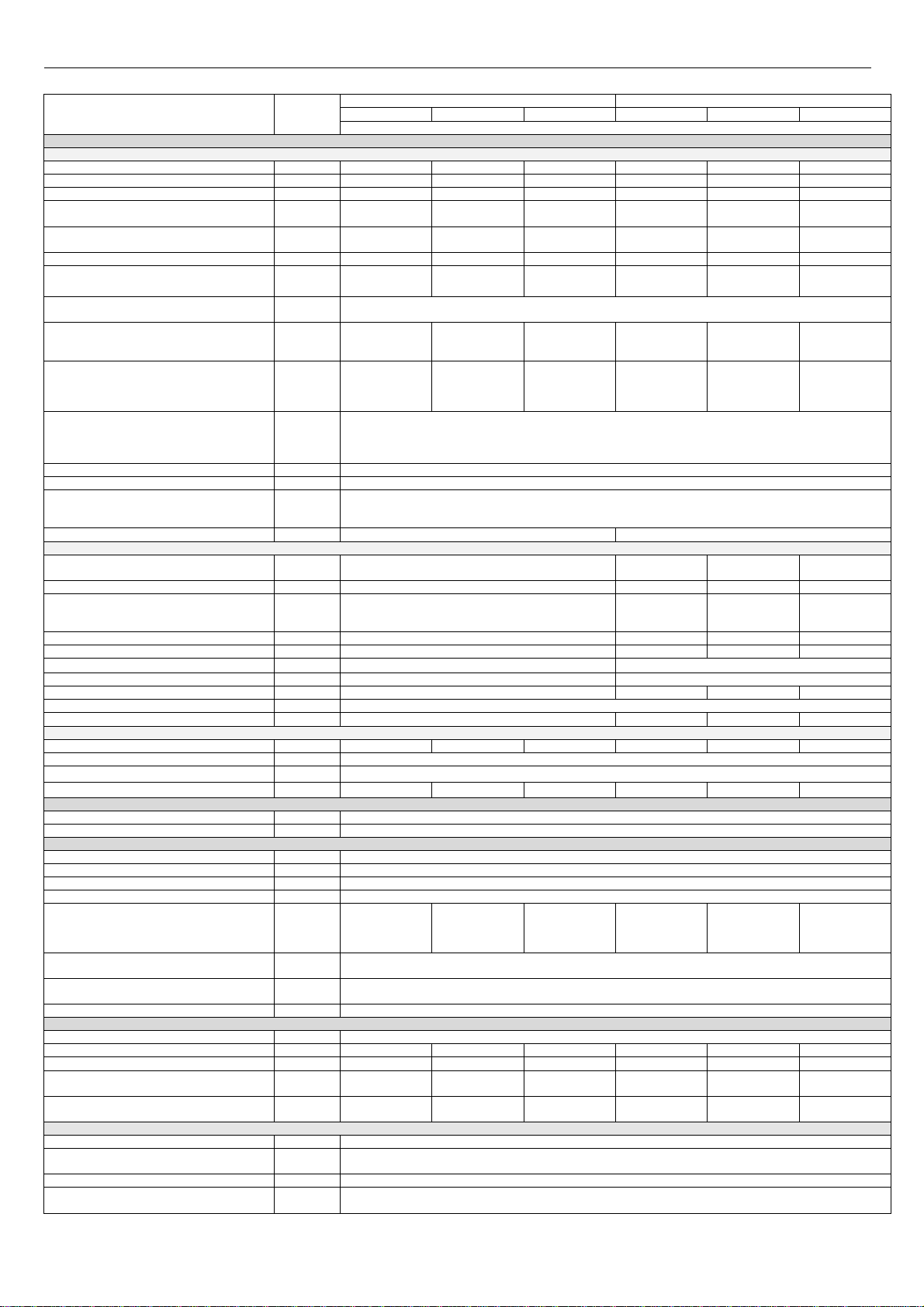
2.2.2. Technical data ........................................................................................................................................................................................................................................................... 5
2.3.
P
ROTECTION EQUIPMENT
.......................................................................................................................................................................................................................................................... 6
2.4.
O
PERATION DESCRIPTION
.......................................................................................................................................................................................................................................................... 6
2.4.1. Way of heating the water for central heating system ................................................................................................................................................................................................ 6
2.4.2. Temperature regulation dependent on e ternal temperature ................................................................................................................................................................................... 6
2.4.3. Method of D.H.W. heating in combi boilers ............................................................................................................................................................................................................... 7
2.4.4. The way of heating the water in system boiler ECOCONDENS SILER PLUS cooperating with domestic water tank. ................................................................................................... 7
2.4.5. Operation of the pump with adjustable speed. ......................................................................................................................................................................................................... 8
3. BOILER INSTALLATION ............................................................................................................................................................................................................................................................... 9
3.1.
R
EQUIREMENTS OF BOILER INSTALLATION
...................................................................................................................................................................................................................................... 9
3.1.1. The regulations on the water installation, gas and the flue gas system ..................................................................................................................................................................... 9
3.1.2. Regulations related to the room ................................................................................................................................................................................................................................ 9
3.1.3. Requirements for electrical installation .................................................................................................................................................................................................................... 9
3.2.
P
RELIMINARY CHECK ACTIVITIES
................................................................................................................................................................................................................................................ 10
3.3.
M
OUNTING THE BOILER ON THE WALL
........................................................................................................................................................................................................................................ 10
Fig. 3.3.1 Installation dimensions of boiler ECOCONDENS SILVER PLUS ............................................................................................................................................................................. 10
3.4.
C
ONNECTION TO THE GAS INSTALLATION
..................................................................................................................................................................................................................................... 10
3.5.
C
ONNECTION OF THE BOILER TO A WATER SYSTEM OF CENTRAL HEATING
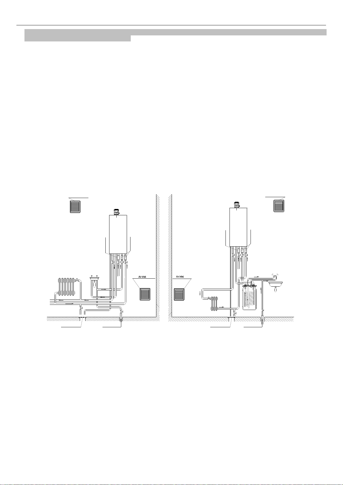
............................................................................................................................................................................................. 10
Fig. 3.5.1 Boilers installation requirements ........................................................................................................................................................................................................................ 11
3.5.2 System cleaning and water treatment for the C.H. filling. ......................................................................................................................................................................................... 11
3.6.
C
ONNECTION OF THE BOILER TO A DOMESTIC HOT WATER SYSTEM
.................................................................................................................................................................................................... 12
3.7.
C
ONDENSATE OUTLET
............................................................................................................................................................................................................................................................. 12
3.8.
F
LUE GAS OUTLET
.................................................................................................................................................................................................................................................................. 12
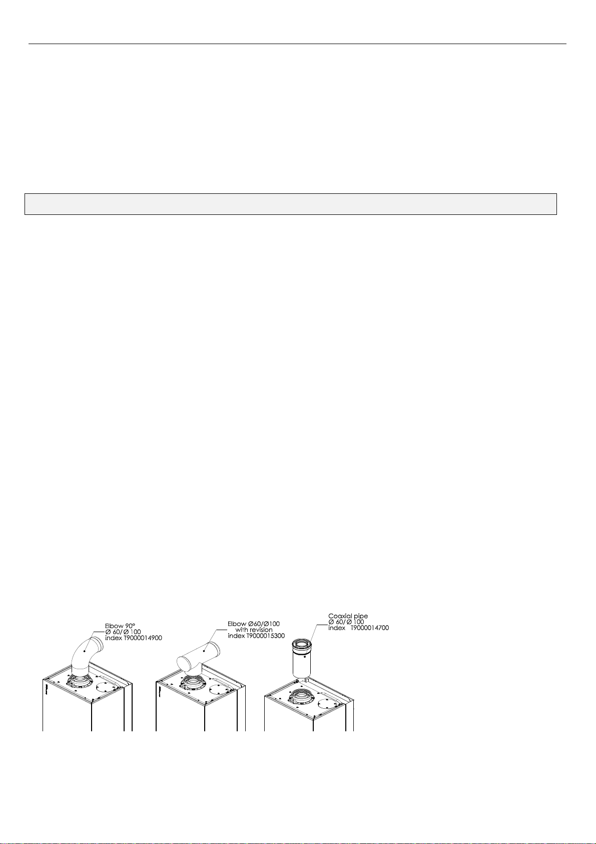
3.8.1. The ways of mounting adapters (elbows connection) to the boiler type .................................................................................................................................................................. 12
3.8.2. Horizontal outlet of air- flue system through the wall or on the roof ....................................................................................................................................................................... 13
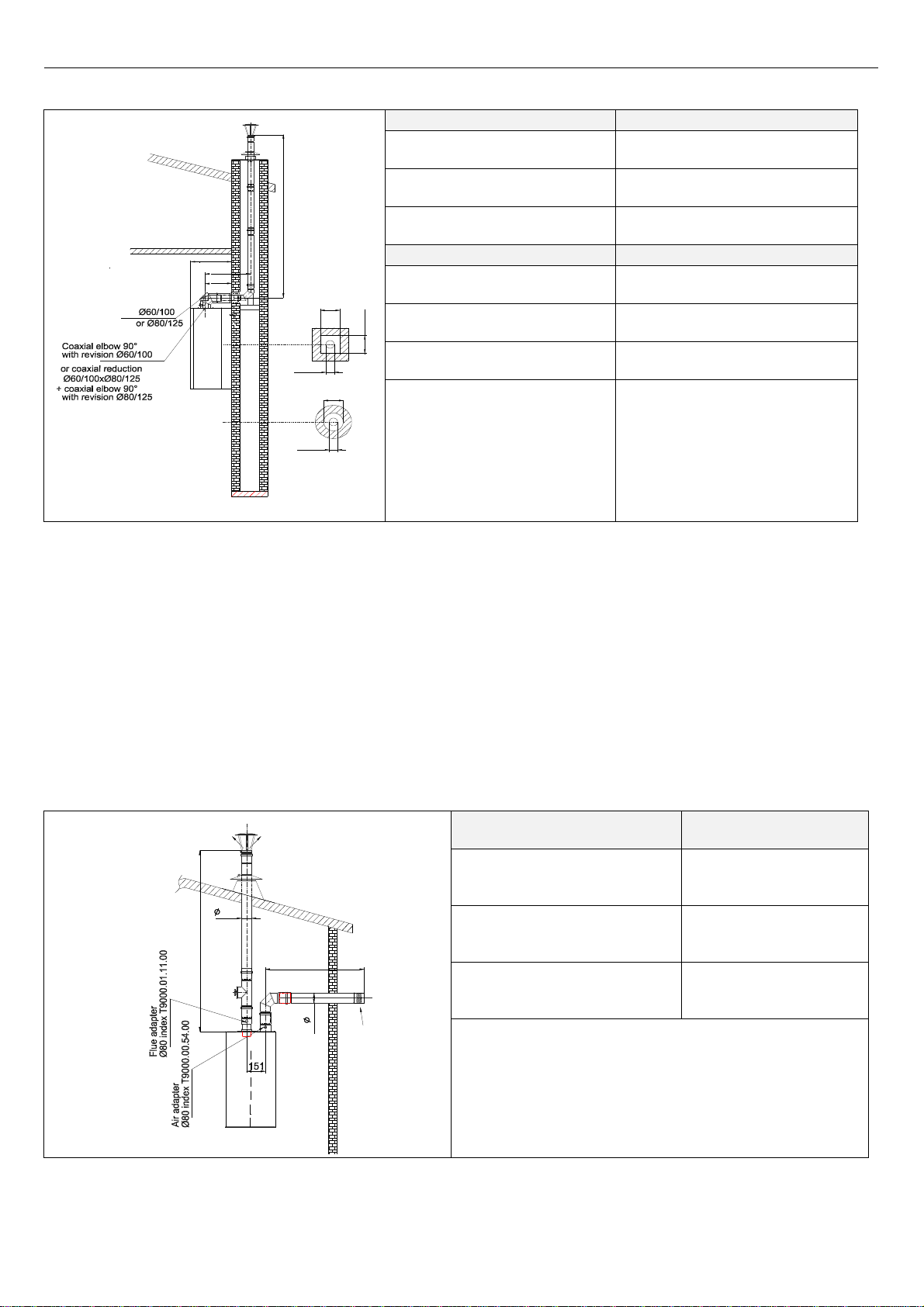
3.8.3 Vertical outlet of air- flue gas system through the roof ............................................................................................................................................................................................ 13
3.8.4 Connecting to a common chimney duct system, consisting of a duct for air inlet and flue gas outlet duct ............................................................................................................... 13
3.8.5. Flue gas air outlet and air inlet by two separate tubes ........................................................................................................................................................................................... 14
3.8.6 Reduction of the ma imum length of the air-flue system by changing the flow direction ......................................................................................................................................... 15
3.9.
C
ONNECTION OF ADDITIONAL DEVICES
........................................................................................................................................................................................................................................ 15
Fig.3.9.1 Electrical terminals of controller - a back view .................................................................................................................................................................................................... 15
3.9.2 Connection of a room temperature regulator ........................................................................................................................................................................................................... 15
3.10.
C
ONNECTING THE OUTSIDE TEMPERATURE SENSOR
...................................................................................................................................................................................................................... 15
4. BOILER ADJUSTMENT AND PRELIMINARY SETTING ................................................................................................................................................................................................................ 15
4.1.
I
NTRODUCTORY REMARKS
....................................................................................................................................................................................................................................................... 15
4.2.
A
DJUSTING THE BOILER TO COMBUST ANOTHER TYPE OF GAS
........................................................................................................................................................................................................... 15
4.3.
B
OILER ADJUSTMENT
............................................................................................................................................................................................................................................................. 16
4.3.1. Gas flow regulation in the boiler (without using the flue gas analyzer) ................................................................................................................................................................... 16
4.3.2. Adjustment of the boiler with a gas analyzer .......................................................................................................................................................................................................... 16
4.4.
F
AN CHARACTERISTICS
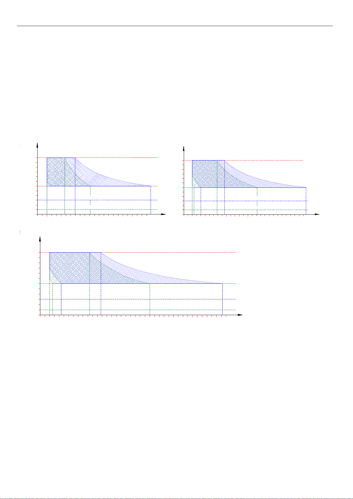
............................................................................................................................................................................................................................................................ 17
F
IG
.4.4.1.
C
HARACTERISTICS OF THE FAN
-
TYPE
NG40
M
...................................................................................................................................................................................................................... 17
5. STARTUP AND OPERATION OF THE BOILER .............................................................................................................................................................................................................................. 17
5.1.
I
NITIAL STARTUP OF THE BOILER
................................................................................................................................................................................................................................................ 17
5.2.
I
NCLUSION AND OPERATION
..................................................................................................................................................................................................................................................... 17
5.3.
O
PERATING MODES OF THE CONTROLLER
.................................................................................................................................................................................................................................... 18
5.4.
S
IGNALIZATION OF OPERATION STATES AND DIAGNOSIS
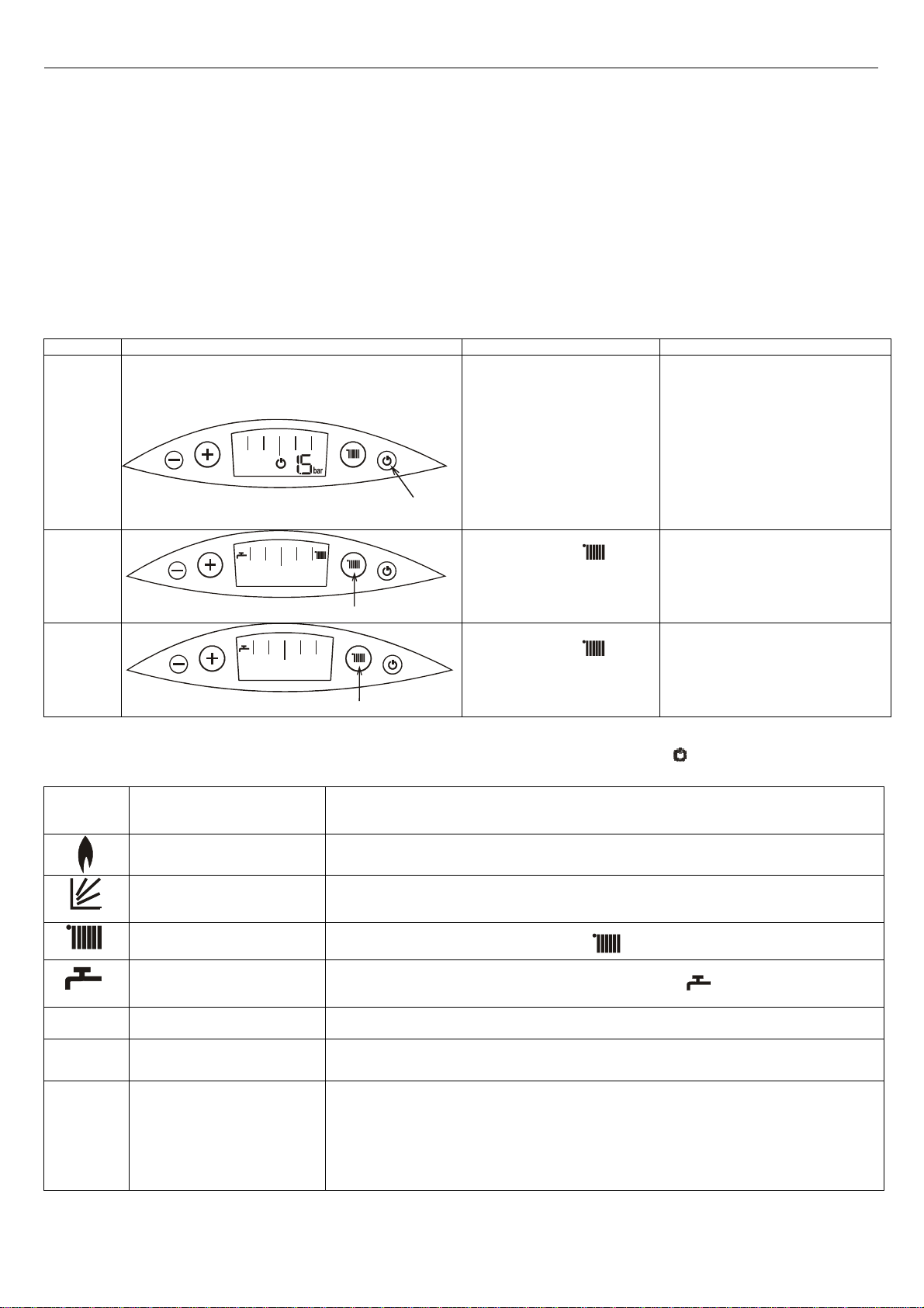
................................................................................................................................................................................................................... 18
5.4.1. Signalisation of the start of heating in CH or DHW system ...................................................................................................................................................................................... 19
5.4.2. Signalisation of anti-freezing function operation in STAND BY mode ....................................................................................................................................................................... 19
5.4.3. Displaying the water pressure in CH installation ...................................................................................................................................................................................................... 19
5.4.4. Displaying parameters ............................................................................................................................................................................................................................................. 19
5.4.5 DHW heating blockade indicator for one-function boilers. ....................................................................................................................................................................................... 19
5.4.6 Support the venting of heating system ..................................................................................................................................................................................................................... 19
5.5.
C
HANGING THE
CH
OR
DHW
TEMPERATURE SETTINGS
.................................................................................................................................................................................................................. 19
5.5.1. Temperature settings in CH circuit ........................................................................................................................................................................................................................... 19
5.5.2 Temperature settings in DHW circuit ........................................................................................................................................................................................................................ 20
5.6.
C
ONTROLLER CONFIGURATION
–
BOILER PARAMETERS SETTING
........................................................................................................................................................................................................ 20
5.6.1. Programming Mode entering .................................................................................................................................................................................................................................. 21
5.7.
P
AUSE IN BOILER OPERATION
................................................................................................................................................................................................................................................... 21
5.8.
D
IAGNOSIS
.......................................................................................................................................................................................................................................................................... 21
5.8.1. Signalisation of error codes during the emergency procedures implementation ...................................................................................................................................................... 21
5.8.2. Signalisation of error codes in emergency situations without locking ...................................................................................................................................................................... 21
5.8.3. Signalisation of emergency switching off with locking ............................................................................................................................................................................................. 21
5.8.4. Error list ................................................................................................................................................................................................................................................................... 22
6. MAINTENANCE, INSPECTIONS, CHEC ING OF THE OPERATION ............................................................................................................................................................................................... 23
6.1.I
NSPECTON AND MAINTENANCE
................................................................................................................................................................................................................................................. 23
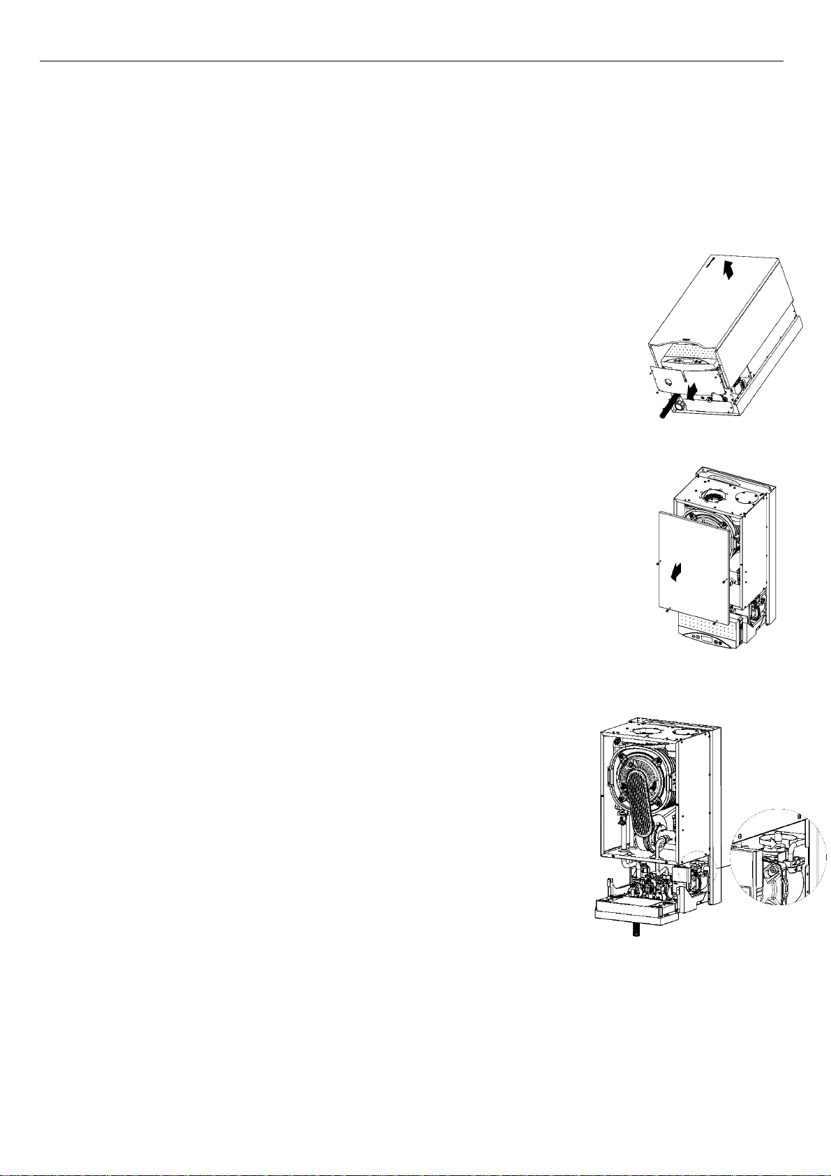
6.1.1. Maintenance of the combustion chamber, burner, electrode. ................................................................................................................................................................................. 23
6.1.2. Cleaning the condensate siphon .............................................................................................................................................................................................................................. 23
6.1.3. The pressure in the e pansion vessel ....................................................................................................................................................................................................................... 23
6.1.4. Maintenance of the flue water-water heat e changer, item.21 ............................................................................................................................................................................... 24
6.1.5. Checking the temperature sensors ........................................................................................................................................................................................................................... 24
6.1.6. Checking the water pump operation ........................................................................................................................................................................................................................ 24
6.1.7. Ionisation current measurement .............................................................................................................................................................................................................................. 24
6.2.
R
EPLACING A DAMAGED CONTROL BOARD IN THE CONTROL PANEL
.................................................................................................................................................................................................... 25
6.3.
T
HE MAINTENANCE OPERATIONS TO BE PERFORMED BY THE USER
...................................................................................................................................................................................................... 26
6.4.
R
ANGE OF TECHNICAL MAINTENANCE PERFORMED BY SERVICE COMPANY
............................................................................................................................................................................................ 26
7. BOILER EQUIPMENT ................................................................................................................................................................................................................................................................. 26