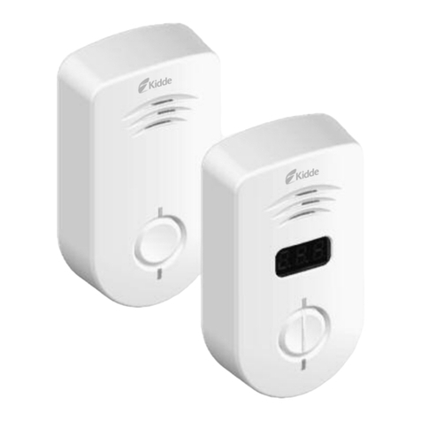
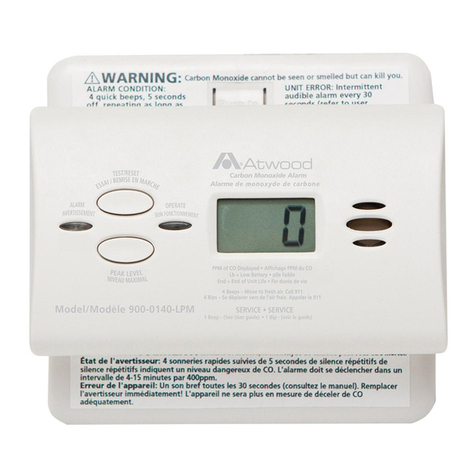
Textron Cessna SL-05-002B Service manual

Cessna Aircraft Company P.O. Box 7706, Wichita, Kansas 67277, USA (316) 517-5800 Facsimile (316) 942-9006
COPYRIGHT © 2008
________________________________________________________________________________________________
Cessna Aircraft Company cannot be responsible for the quality of work performed by others while fulfilling the
requirements of this Service Letter. Procedures specified in this Service Letter must be accomplished using industry
standard maintenance practices and applicable government regulations. Page 1 of 6
SERVICE LETTER
S
SSSL
LLL-
---0
0005
555-
---0
0000
0002
222B
BBB
March 25, 2008
Model 350/400
Carbon Monoxide Detector
Carbon Monoxide DetectorCarbon Monoxide Detector
Carbon Monoxide Detector
EFFECTIVITY
EFFECTIVITYEFFECTIVITY
EFFECTIVITY
Cessna LC42-550FG aircraft serial numbers 42002 through 42062 and Cessna LC41-550FG serial numbers
41002 through 41055.
REVISION HISTORY
REVISION HISTORYREVISION HISTORY
REVISION HISTORY
Rev Description Date
N/A Initial Release August 31, 2005
A Updated to reflect company name change to Cessna December 11, 2007
B Updated to correct company name change revision March 25, 2008
PURPOSE
PURPOSEPURPOSE
PURPOSE
For installation the Carbon Monoxide detection system.
COMPLIANCE
COMPLIANCECOMPLIANCE
COMPLIANCE
Note: If this letter has been complied with at a previous revision no further compliance is required.
Not mandatory; shall be complied with at aircraft owner’s discretion.
APPROVAL
APPROVALAPPROVAL
APPROVAL
FAA approval has been obtained on all technical data in this Service Letter that affects type design.
RESOURCES
RESOURCESRESOURCES
RESOURCES
Five (5) hours of labor required for compliance with this Service Letter. This does not qualify for warranty
labor reimbursement.
MATERIAL INFORMATION
MATERIAL INFORMATIONMATERIAL INFORMATION
MATERIAL INFORMATION
The following materials are required for compliance with this Service Letter. Parts can be obtained from
Cessna Aircraft Company.
ITEM NO. DESCRIPTION P/N OR SPEC. SUPPLIER QUANTITY
1 Service Letter SL-05-002B Cessna 1
2 Carbon monoxide kit COK Cessna 1
INSTRUCTIONS FOR COMPLIANCE
INSTRUCTIONS FOR COMPLIANCEINSTRUCTIONS FOR COMPLIANCE
INSTRUCTIONS FOR COMPLIANCE
1. Detach the aircraft battery leads to remove power from the electrical system per the Cessna
350/400 AMM.
2. Remove the forward left hand interior side panel per the Cessna 350/400 AMM.

Cessna Aircraft Company P.O. Box 7706, Wichita, Kansas 67277, USA (316) 517-5800 Facsimile (316) 942-9006
COPYRIGHT © 2008
________________________________________________________________________________________________
Cessna Aircraft Company cannot be responsible for the quality of work performed by others while fulfilling the
requirements of this Service Letter. Procedures specified in this Service Letter must be accomplished using industry
standard maintenance practices and applicable government regulations. Page 2 of 6
3. Remove the glare shield per the Cessna 350/400 AMM.
4. Remove the multi-function display per the Cessna 350/400 AMM and store securely.
5. Locate part number of existing aural warning box to insure that it has the CO capability. The last
four digits of the part number required must be 0102 or higher, if this is not the part number return
the unit to PS Engineering for revision to accommodate CO.
6. Mount CO detector (P/N 452-201-003) to bracket (P/N LB53311431) using hardware found in the
detector installation kit and two (2) lock washers (P/N MS35338-42). Reference Figure 1.
NOTE: Observe instructions in all Figure flag notes.
7. Install mounted CO detector assembly on the center gusset attached aft of the firewall using the
existing hardware that attaches the K-16 relay. Reference Figure 1.
8. Attach wiring harness (P/N LB53344905-1) to the CO detector, securely route and terminate
connections per Figure 2. If there is an existing wire in pin 10 of the J132 connector at the aural
warning unit, cap and stow the wire and run the wire labeled “J132 Pin 10” to the appropriate
location on the J132 connector.
9. Remove the annunciator panel and replace the overlay with new (P/N LB53311411D1-19 for the
350 and LC53311411A-1 for the 400).
10. Install circuit breaker (P/N 7277-2-2) in vacant hole on circuit breaker panel and install placard
(P/N LB53314117-1) below circuit breaker on circuit breaker panel. Reference Figure 3.
11. Run new 22 AWG wire (P/N M22759/16-22-9) from J63 pin 23 crimping pin P/N 66105-4 and
run to the circuit breaker crimping terminal P/N 36152 and attach to circuit breaker using circuit
breaker hardware. Reference Figure 3.
12. Remove instruments from left hand instrument plate and drill .25” hole in plate to receive
test/reset switch (P/N LA53344203-3) and install switch
13. Reinstall instruments to instrument plate and reinstall plate. Reference Figure 1.
14. Install CO detector placard (P/N LB53114117-1) above switch and test/reset placard (P/N
LB53114117-2) below switch.
15. Attach the aircraft battery leads to apply power to the electrical system per the Cessna 350/400
AMM.
16. Operationally test per Figure 4, and insert Figure 4 into the Section 9 of the AFM.
17. Ensure both the master and avionics switches are in the off position.
18. Reinstall the multi-function display, glare shield, and interior in reverse order of removal per the
Cessna 350/400 AMM.
19. Update weight and balance and equipment list.
20. Make log entry stating compliance with this Service Letter, SL-05-002B.

Cessna Aircraft Company P.O. Box 7706, Wichita, Kansas 67277, USA (316) 517-5800 Facsimile (316) 942-9006
COPYRIGHT © 2008
________________________________________________________________________________________________
Cessna Aircraft Company cannot be responsible for the quality of work performed by others while fulfilling the
requirements of this Service Letter. Procedures specified in this Service Letter must be accomplished using industry
standard maintenance practices and applicable government regulations. Page 3 of 6
Figure 1
1. CO detector, P/N 452-201-003
2. Detector bracket, P/N LB53311431
3. Washers, MS35338-42

Cessna Aircraft Company P.O. Box 7706, Wichita, Kansas 67277, USA (316) 517-5800 Facsimile (316) 942-9006
COPYRIGHT © 2008
________________________________________________________________________________________________
Cessna Aircraft Company cannot be responsible for the quality of work performed by others while fulfilling the
requirements of this Service Letter. Procedures specified in this Service Letter must be accomplished using industry
standard maintenance practices and applicable government regulations. Page 4 of 6
Figure 1 (cont’d)
4. Connector, J191
5. Switch, P/N LA53344203-3
6. CO detect placard, P/N LB53114117-1
7. CO test/reset placard, P/N LB53114117-2
Figure 2

Cessna Aircraft Company P.O. Box 7706, Wichita, Kansas 67277, USA (316) 517-5800 Facsimile (316) 942-9006
COPYRIGHT © 2008
________________________________________________________________________________________________
Cessna Aircraft Company cannot be responsible for the quality of work performed by others while fulfilling the
requirements of this Service Letter. Procedures specified in this Service Letter must be accomplished using industry
standard maintenance practices and applicable government regulations. Page 5 of 6
Figure 3
1. Circuit breaker, P/N 7277-2-2
2. Ring terminal, P/N 36152
3. Crimp pin, P/N 66105-4
4. Wire, M22759/16-22-9
5. Placard, P/N LB53314117-1

Cessna Aircraft Company P.O. Box 7706, Wichita, Kansas 67277, USA (316) 517-5800 Facsimile (316) 942-9006
COPYRIGHT © 2008
________________________________________________________________________________________________
Cessna Aircraft Company cannot be responsible for the quality of work performed by others while fulfilling the
requirements of this Service Letter. Procedures specified in this Service Letter must be accomplished using industry
standard maintenance practices and applicable government regulations. Page 6 of 6
Figure 4
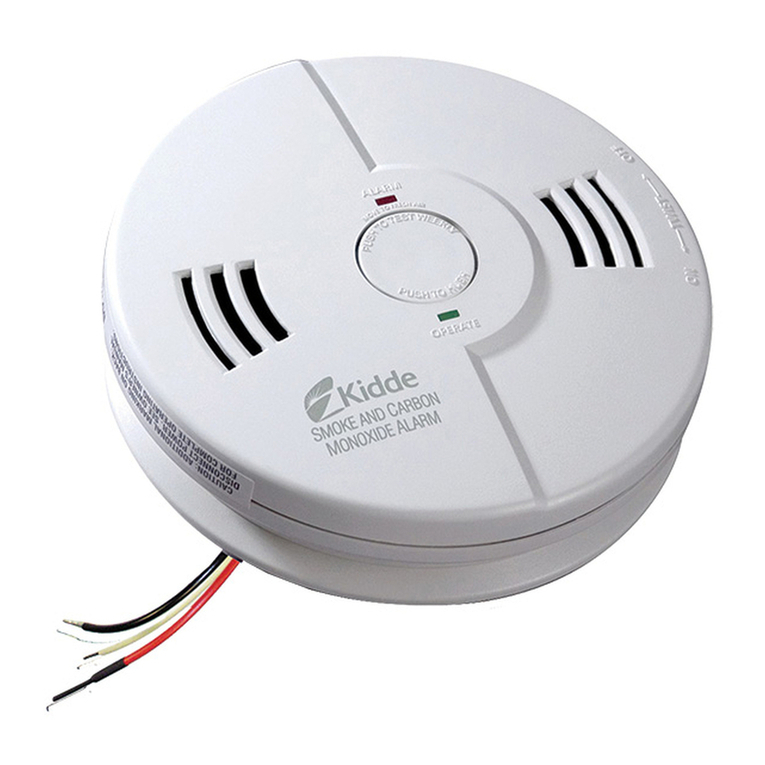
CO GUARDIAN CARBON MONOXIDE DETECTOR
The Model 452-201 Series Carbon Monoxide Detector is designed to detect, measure,
and provide a visual and aural alert to the pilot before the level of carbon monoxide
(CO) reaches a critical level.
The installation consists of a single carbon monoxide detector installed behind the
instrument panel that activates a red annunciator and an aural warning. The aircraft
supplied power and aircraft wiring is protected by a 2 amp circuit breaker. There is a
test/reset button located on the left hand side of the engine instruments panel between
the fuel quantity indicator and manifold pressure/fuel flow gauge. A red light is
located on the annunciator panel.
The carbon monoxide alarm level is calibrated to alert the pilot within five minutes or
less whenever the carbon monoxide level reaches 50 parts per million (PPM) by
volume or above. The warning time is shortened at higher levels of CO
concentrations and becomes approximately instant should the CO level reach 400
parts per million by volume (PPM) or above.
In case of a CO alert, the red annunciator will illuminate continuously and the aural
warning will state “Carbon Monoxide” every two seconds. The visual alert will
remain until the CO level is again reduced below the alert level. The aural warning
may be silenced by pressing the ACK button on the annunciator panel. The indicator
is automatically reset when the CO level drops below 50 PPM.
On initial power up, the detector goes through a self-test and the annunciator light
flashes twice, but the aural warning will remain off. There will be a three minute
warm-up time before the detector is operational. To test the system any time, press
and release the test/reset switch. As on initial power up, the detector goes through a
self-test and the annunciator light will flash twice, but the aural warning will remain
off. To reset the system, press the test/reset switch and assure that the annunciator
light flashes twice. If the detector sensor fails, the annunciator light will flash every 4
seconds, but the aural warning will not sound.
Table of contents
