The Don Classics NV73EQ User manual

the DON classics
www.thedonclassics.com
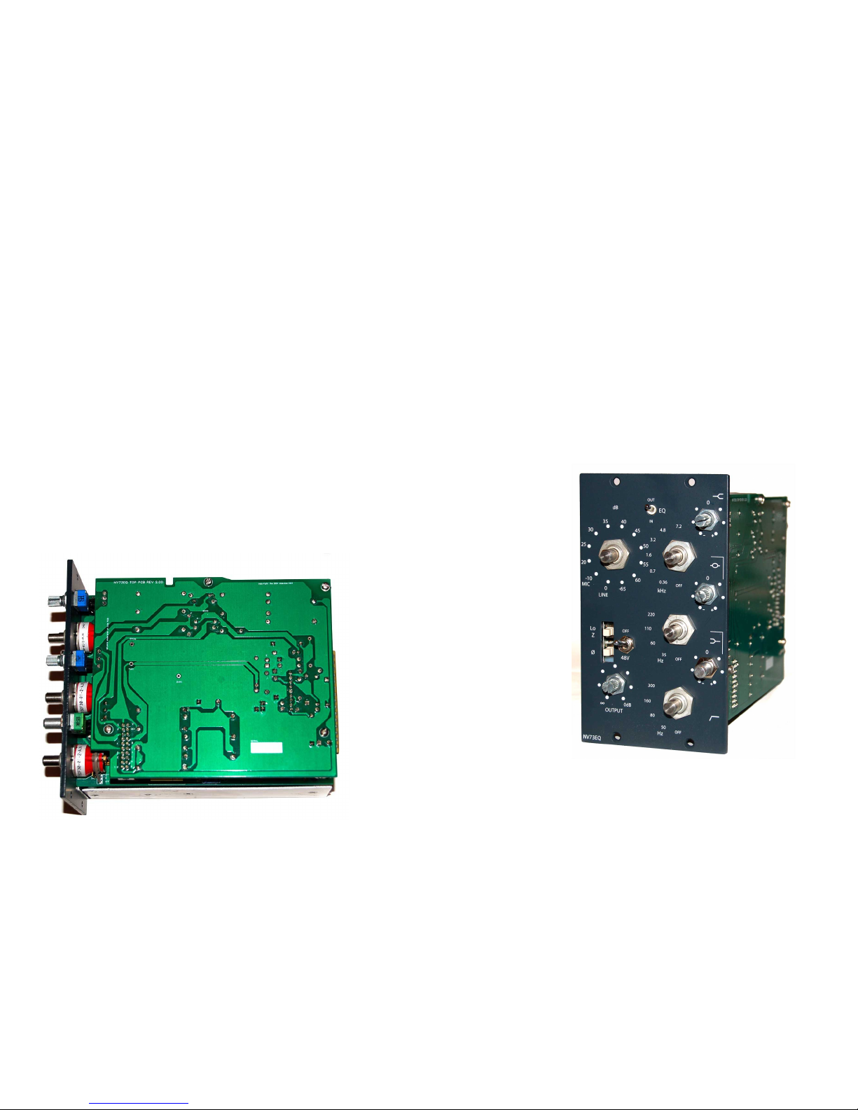
NV73EQ
(ADD-ON)
ASSEMBLY GUIDE
REV: 1:00
© the DON classics 2015 page 1 of 20

QUICK A EMBLY GUIDE
8 STEPS TO EQ HEAVEN!
1. Place/solder parts on PCB
2. Fit rotary switch pins
3. Wire pots
4. Make ribbon cable
5. Wire to NV73 micpre
6. Place PCBs in metal work
7. Initial test
8. Attach knobs
Equalise!
NOTE: This anual assu es that you already have a fully working 'NV73' icpre and are
upgrading it to the 'NV73EQ' with the 'NV73EQ-Add-on'
© the DON classics 2015 page 2 of 20

Frequently Asked Questions (FAQ)
Q. What is the difference bet een the 'NV73EQ' & 'NV73EQ add-on'?
A. The 'NV73EQ' is a 2 space ic-pre & EQ unit.
The 'NV73EQ-Add-on' is for people already with the NV73 ic-pre who want to upgrade it to the 'NV73EQ'
Q. What is included in the addon kit?
A. Everyth ng ncluded on th s page s ncluded n the k t from us.
Q. What other orders do I need to make?
A. You need to make 2 other orders as deta led on th s page.
Q. Is there a schematic that ould be useful?
A. For reference you can download the NV73EQ schemat cs from the DON class cs webs te. NV73EQ Schemat cs
PCB des gnat ons reference th s.
Q. Who can build this?
A. You!
As long as you have pat ence and are thorough n your work, anyone can bu ld th s add-on. There's not a lot to the c rcu try
and s qu ck to complete w th very m n mal w r ng. There's lots of support and nformat on and t s tr ed and tested.
Q. Ho close to the original does it sound?
A. Spot on. We have chosen not to do any “new and mproved” updates on a c rcu t that sounds so good. We have chosen the
same parts that was used or g nally and recommend th s. Th s ncludes large footpr nts for the mustard caps / polystyrene caps
wh ch were used n the v ntage un t. And the add-on c rcu t jo ns to the m c-pre n exactly the same way as the v ntage un t.
© the DON classics 2015 page 3 of 20

1. older parts on PCB
When nsert ng parts there are 3 resources that w ll be useful.
A) ilkscreen images (eg. for any hard to read designations)
S lkscreens can be downloaded on the manual page: s lkscreens
B) General BOM (eg. For ore info on specific parts/values)
General BOM can be found on the manual page: General BOM
C) chematic (eg. For general confir ation of circuit)
General BOM can be found on the manual page: Schemat cs
Armed w th that nfo, let's start!
Insert all parts on to the PCB as marked on the s lkscreen. All designations and values for parts are arked on the PCB for ease
TIP :
Start w th smaller parts (res stors etc.) and work up to the larger parts
Solder nl ne sockets for trans stors on both EQ boards
F t bottom parts f rst on BTM PCB as there'll be less room to solder up top.
Make sure no metal legs protrude too much on the TOP PCB
All the small 1/8W s zed res stors near the rotary sw tches are 4M7 f not stated otherw se.
Green molex K & 24V open ng should face the m ddle rotary sw tch
Green molex P & 0V open ng should face the PCB cutout
The 47pF caps are a hot top c.. some v ntage un ts have them removed, some don't. They exh b t a large drop n the top end when
EQ s pushed n, however f you are try ng to emulate a part cular v ntage un t then the footpr nt s there. It's up to you!
© the DON classics 2015 page 2 of 20
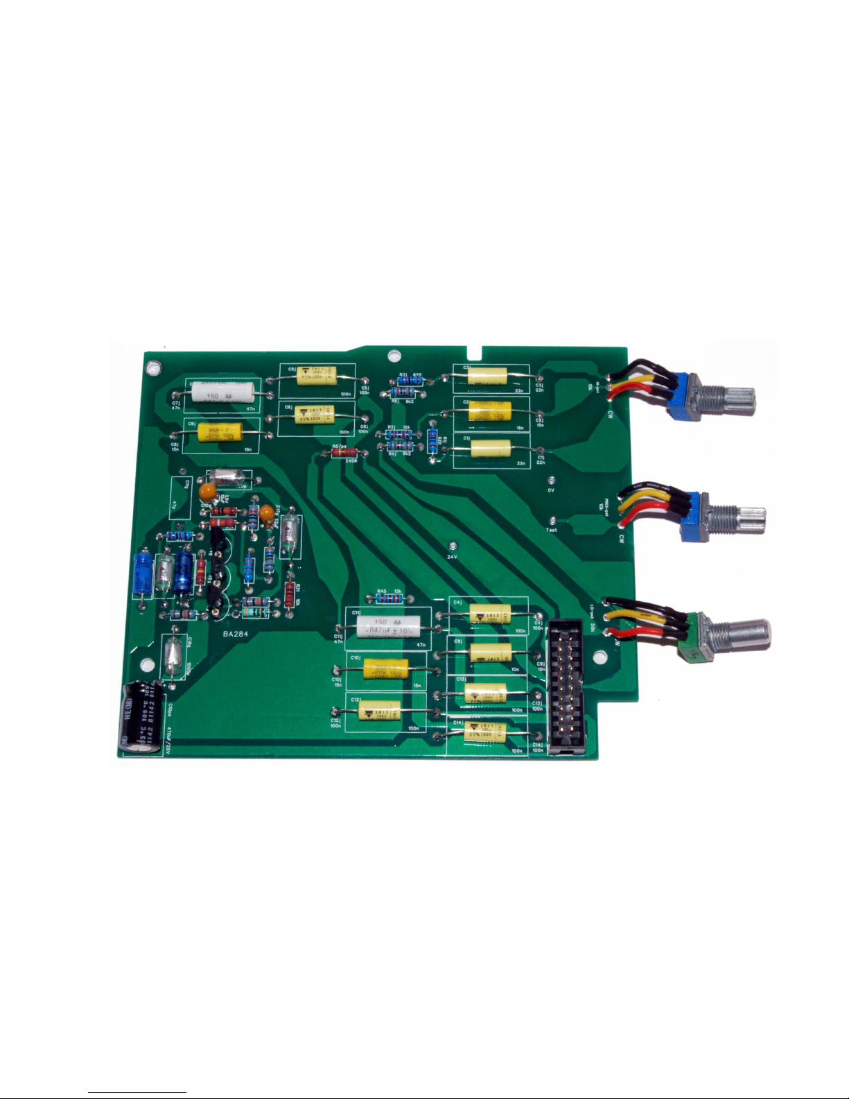
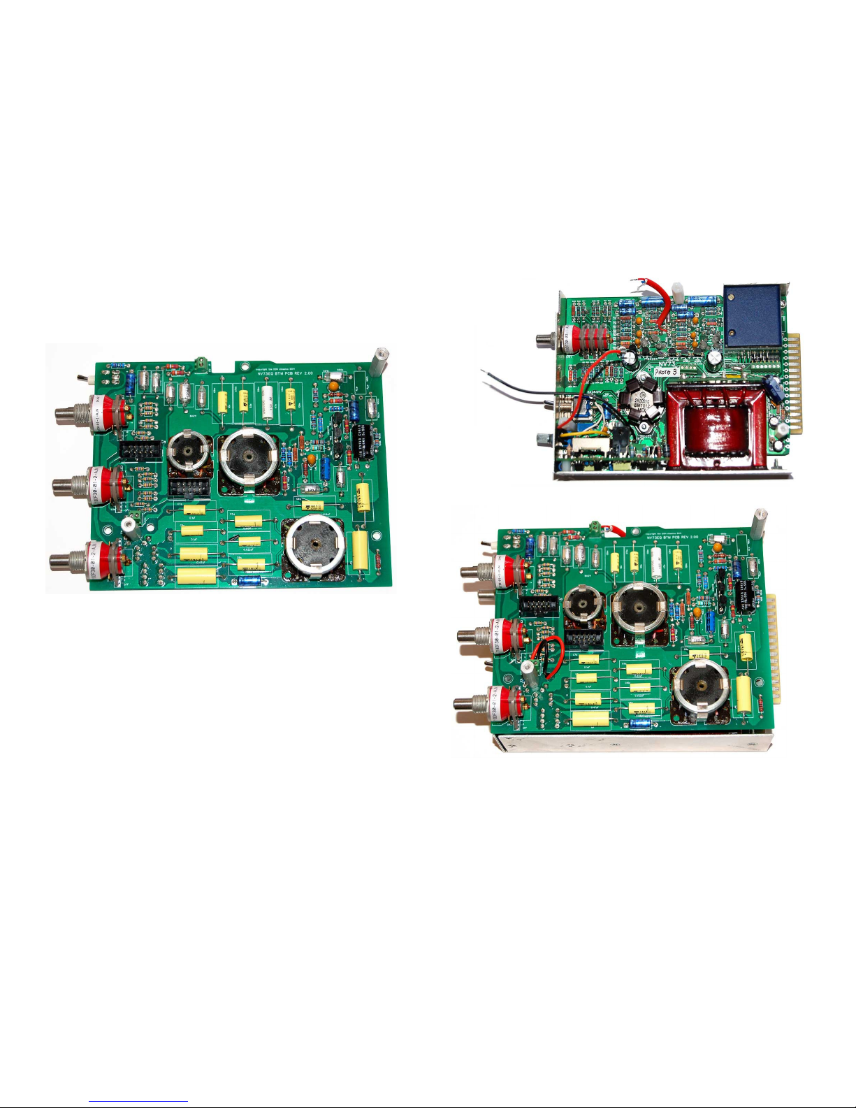
PCBs should end up looking like this...
TOP PCB:
© the DON classics 2015 page 5 of 20

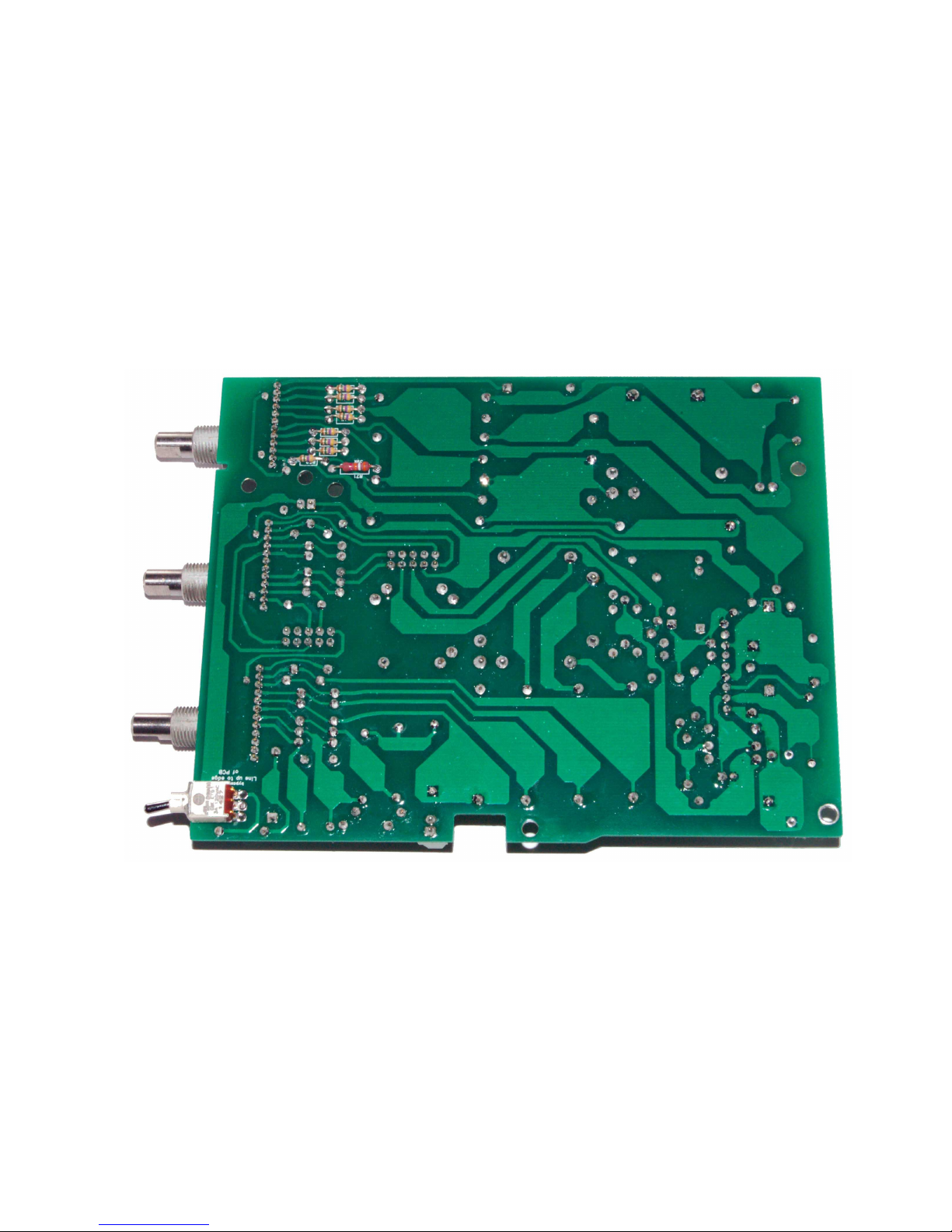
TOP PCB (underside):
© the DON classics 2015 page 2 of 20

BTM PCB:
© the DON classics 2015 page 7 of 20
BTM PCB (underside):
© the DON classics 2015 page 2 of 20

2. Fit rotary switch pins as shown
Before nsert ng the stopper p ns conf rm that the common leg shorts to leg 1 of the sw tch (edge closest the common p n)
If t doesn't, tw st the shaft to the pos t on where t does. OR nsert the p n n 12 o'clock, and then tw st the shaft
ant clockw se all the way. (E ther method w ll work)
F t the stopper p ns n the pos t ons shown (or a bit of co ponent leg if you have isplaced the pins!)
Place the metal st cker over the p ns (remove the nner m ddle c rcle st cker)
NOTE: For the presence setting (there was an extra position of 10kHz. Achieved si ply by an extra cap in an extra switch position.
I've included this cap so you will have the extra position of 10kHz.
If you prefer, you can of course set this rotary switch to just the 7 positions like the 1073 & front panel.
© the DON classics 2015 page 9 of 20
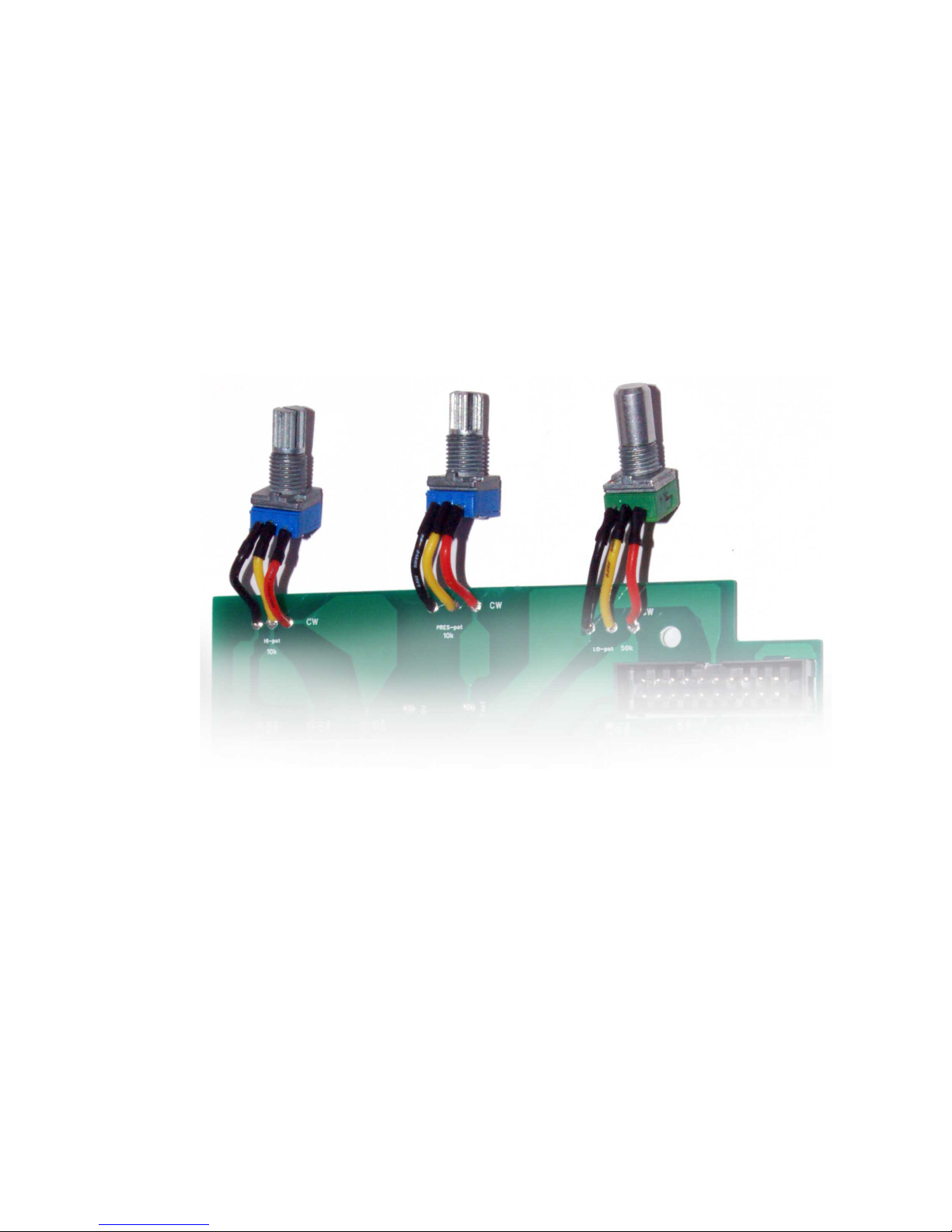
3. Wire the pots
W re pots as shown:
TIP: A little heatshrink will keep things neat and ake sure no shorts happen between connections.
© the DON classics 2015 page 2 of 20
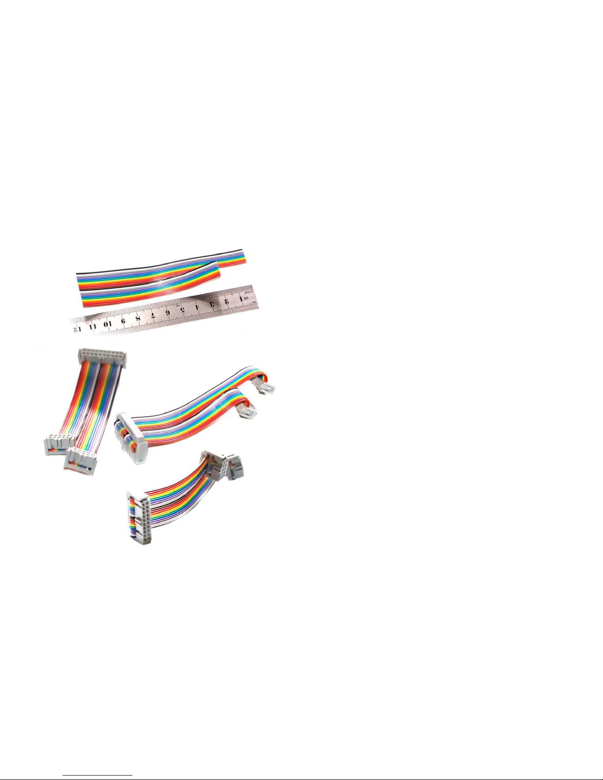
4. Make ribbon cable
Cut the 20way r bbon cable as shown n cm
(using scissors, cut straight and not off angle)
(Split the ribbon cable down the iddle along half its length)
Black s p n 1 as shown.
Make sure black w ll connect to p n 1 of the IDC headers.
(The triangles are pin 1 on the IDC headers.)
Make sure the headers l ne up as shown.
(Red will be pin 1 if using a grey ribbon cable)
One at a t me l ne up the headers correctly
(straight so the teeth line up & is not crooked)
Push down with fingers until it grips and confirm all is lined up.
Flush or overhang ng the edge a l ttle s correct.
Keep apply ng f rm pressure so t doesn't sl p out.
Squash n a v ce or use a handheld IDC tool.
It w ll cl p nto place.
Conf rm the 2 s de edge teeth pop through.
Once f tted, bend back the r bbon cable and f t stra n rel ef
cl ps.
Spl t the cable further long the m ddle to ncrease flex b l ty
when plugg ng n the PCBs
© the DON classics 2015 page 11 of 20

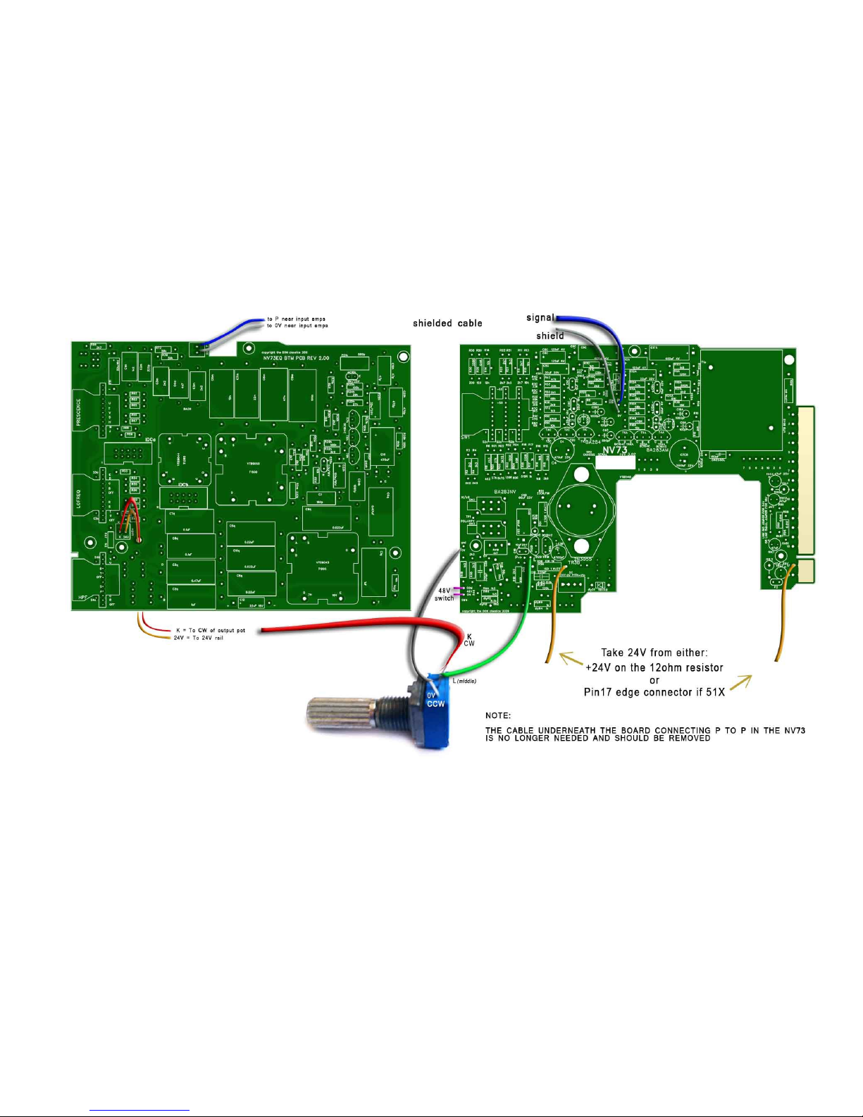
5. Wire to NV73 micpre
Remove the sh elded cable on the bottom of the NV73 m c pre PCB.
Remove the CW w re on the output ga n potent ometer on the NV73.
Cut and str p a sh elded cable as shown for P & 0V.
Cut and str p 2 w res for K & 24V.
Place the BTM PCB roughly in place as a reference for how long the wires should be.
Solder w res as shown.
The K & 24V w res can poke up through the extra hole n the BTM PCB.
The next page shows the connections...
© the DON classics 2015 page 2 of 20
© the DON classics 2015 page 13 of 20
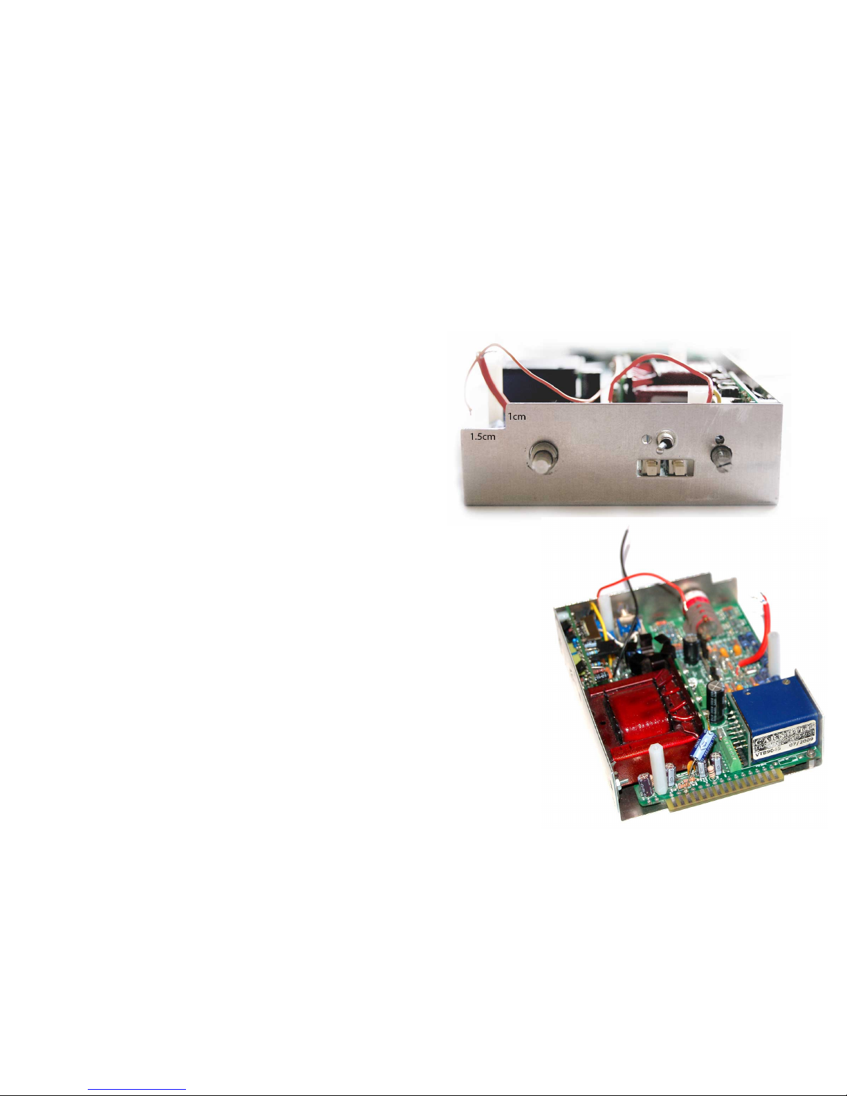
6. Fit metal work
Cut a small section off the corner of the L-bracket to fit the
new EQ bypass switch.
Use aviation snips for less mess.. or a nibbler.. or a
hacksaw/file if you prefer.
It ill be hidden by the front panel, so no need to be too precise.
Prepare the L-bracket like before using the countersunk screws
and standoffs.
Place the one metal standoff like before, near the edge
connector fingers pin1.
And the other nylon standoffs like before.
Fit everything in the NV73 like normal. eg. Transformers, mall P U PCB..
Place in the pot and phantom switch.. use the tabbed washer and make sure they
don't fall back into the unit where it will be difficult to grab once we place on
the other PCBs.
Now the NV73 s together. Secure t n the L-bracket.
For the one metal standoff (near p n 1), use a normal pan head screw l ke
before.
For the other standoffs, use the 3 large nylon male/female standoffs.
Now conf rm the follow ng three th ngs:
1) 2N3055 case should short to output transformer p n 1..
2) Output transformer p ns shouldn't short to ground..
3) Term nal block screws are t ghtened..
© the DON classics 2015 page 2 of 20
Place two 1 nch metal standoff on the BTM PCB as shown below.
Secure w th nut.
Place on the BTM PCB and feed through the w res
T ghten the screws n the two green term nal blocks.
© the DON classics 2015 page 15 of 20
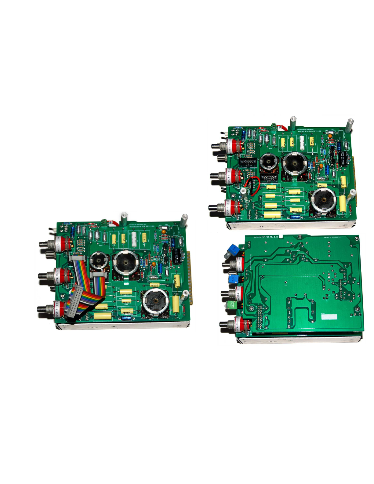
Secure the BTM PCB
Use a small pan head screw for the nylon standoff closest
to the 48V sw tch.
Use metal 1 nch standoffs for the other 2 nylon standoffs.
Insert the r bbon cable nto the BTM PCB and TOP PCB.
Carefully sh ft the r bbon cable unt l the TOP PCB l nes up w th
the standoffs and screw us ng the rema n ng 4 pan head screws.
© the DON classics 2015 page 2 of 20
Before plac ng the front panel t's worth check ng that there s no short on the power ra ls to ground. So conf rm there's no
cont nu ty between the 24V and 0V p ns marked on the top of the PCB and also the edge connectors voltage ra ls and
ground. P ns 1,5 & 13 are ground. P ns 12,14,15 are power ra ls.
(P ns 17 & 18 on 51X are also power ra ls)
(Power rails shouldn't short to each other or to ground.)
(a s all beep when first testing is nor al as the caps charge up.)
Insert front panel carefully mak ng sure the pot and 48V sw tch doesn't fall back nto the un t.
Secure everyth ng w th nuts.
For the phantom sw tch you can reach n w th a long nosed pl ers f needs be to
help when t ghten ng.
Same w th the tab on the small pot. If not, long tweezers could also prevent
turn ng of the body when t ghten ng.
Make use of the bl nd holes n the front panel for the tabs on the potent ometers.
© the DON classics 2015 page 17 of 20

7. Initial test
Turn the unit on!
Once the un t s on, measure to make sure you are read ng +24V You can check on the top where +24V s marked and 0V.
Run some aud o through the un t w th EQ on and off and check that t sounds good and all controls work correctly.
Make sure there s no buzz or hum from the un t.
If all s well then we can f t the knobs...
© the DON classics 2015 page 2 of 20

8. Attach knobs
Allow a l ttle d stance between the knobs and the front panel so the
knobs don't gr b aga nst the front panel.
Use a small flat head screw dr ver. (Use two at the same t me for an
eas er way to secure the knobs evenly.
Use a T2 s zed head screw the small grey knobs on.
Congratulations! Get recording & mixing!
© the DON classics 2015 page 19 of 20

* Further troubleshooting
For more n depth troubleshoot ng tests, t may be worthwh le to bu ld or buy a l ttle
j g to test un ts w thout hav ng to root around n a lunchbox. eg. An EDAC attached
to long w res attached to a PCB w th the 15/18 gold f ngers to nsert to the lunchbox.
(One source of card edge connectors and edge adapters s Jeff's excellent store
class cAPI)
© the DON classics 2015 page 2 of 20
Table of contents
Popular Stereo Equalizer manuals by other brands


Extron electronics
Extron electronics Video and Audio Line Drivers with Gain and EquaLization CVEQ 100... Specifications

Art
Art XL 231 Operation manual

Behringer
Behringer MiniFBQ FBQ800 user manual

Pioneer
Pioneer CD-5 owner's manual

Harman
Harman DBX 20 Series Operation manual

D.W. Fearn
D.W. Fearn VT4 operating instructions


