The Fisher FUTURA F-5593 Installation guide
(c) www.fisherconsoles.com
\
CONGRATULATIONS!
With your purchase of a FISHER instrument you have com-
pleted a chain of events that began many months ago, in our
research laboratories. For it is there that the basic concept of
the equipment you have just acquired came into being-its
appearance, its functions, its quality of performance, its con-
venience of use.
But the end step-your purchase-is merely a beginning. A
door has now opened, for you and your family, on virtually
unlimited years of musical enjoyment. Recognizing that one of
the keys to pleasurable ownership is reliability, we have
designed this instrument to give long and trouble-free service.
In fact, instruments we made over twenty-seven years ago
are still in use today.
Remember always that we want this equipment to give you
the best performance of which it is capable. Should you at
any time need our assistance toward that objective, please
write me personally.
N IMPORT NT SUGGESTION
II
.
Many hours have been spent by our engineers and technical
writers to create this instruction book for your guidance and
enjoyment. If you want the most out of your FISHER, there is
only one way to obtain it. With the equipment before you, please
read this booklet carefully. It will be time well spent:
1tu lA.1(.
il
Founder and President
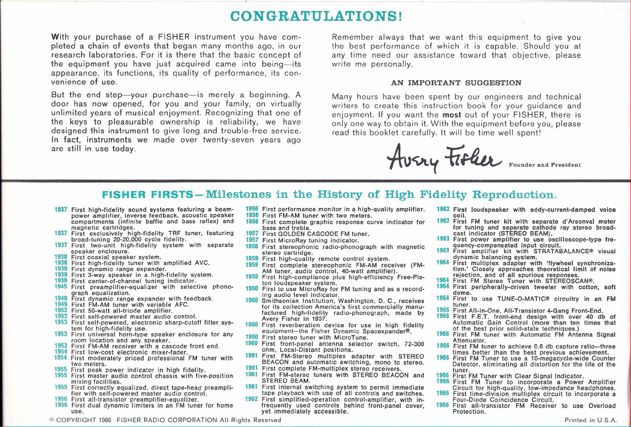
FISHERFIRSTS-Milestones in the History of High Fidelity Reproduction.
1937
First high-fidelity. sound systems Ieaturinq a beam- 1956 First performance m nitor in a high-quality amplifier.
power amplifier, Inverse feedback, acoustic speaker 1956 First FM-AM tuner With two meters.
compartments (infinite baffle and bass reflex) and 1956 First complete graphic response curve indicator for
magnetiC cartridges. . bass and treble.
1937 First exclusively high-fidelity TRF tuner, teaturinq 1957 First GOLDENCASCODEFMtuner.
broad-tuning 20-20,000 cycle fidelity. . 1957 First MicroRay tuning indicator.
1937 First two-unit high-fidelity system With separate 1958 First stereophonic radio-phonograph with magnetiC
speaker enclosure. stereo cartridge.
1938 First coaxial s eaker system. . . 1959 First high-quality remote control system.
1938 First high-fidelity tuner With amplified AVC. 1959 First complete stereophonic FM-AM receiver (FM-
1939 First dynamic range .expander.. . AM tuner, audio control, 40-watt amplifier).
1939 First 3-way speaker In a h,gh-f.,del,ty system. 1959 First high-compliance plus high-efficiency Free-Pis-
1939 First center-of channel tuning !ndlcator. . ton loudspeaker system.
1945 First preamplifier-equalizer With selective phono- 1960 First to use MicroRay for FM tuning and as a record-
graph equalIZation.. ing audio level indicator.
1948 First dynamic range expander With feedback. 1960 Smithsonian Institution, Washington, D. C., receives
1949 First FM-AM tuner. With variable AFC. for its collection America's first commercially manu-
1952 F!rst 50-watt ail-triode amplifier. factured high-fidelity radio-phonograph, made by
1952 First self-powered master audio control. . Avery Fisher in 1937.
1953 First self-powered, electronic sharp-cutoff Illter.svs- 1960 First reverberation device for use in high fidelity
tem for high-fidelity use. equipment-the Fisher Dynamic Spacexpandere.
1953 First universal horn-type speaker enclosure for any 1960 First stereo tuner with MicroTune.
room location and any speaker. 1960 First front-panel antenna selector switch, 72-300
1953 First FM-AM receiver With a cascode front end. ohm Local-Distant positions.
1954 First low-cost electronic mixer-fader. 1961 . ' . .
1954 First moderately priced professional FM tuner with First FM-Stereo multiplex. adapter With STEREO
two meters. BEACON and automatic SWitching, mono to stereo.
19S5First peak power indicator in high fidelity. 1961 First complete FM-multlplex stereo receivers.
1955 First master audio control chassis with five-position 1961 First FM-stereo tuners With STEREO BEACON and
mixing facilities. STEREOBEAM.. . ...
1955 First correctly equalized, direct tape-head prearnpli- 1961 First Internal SWitching system to permit Immediate
lier with self-powered master audio control. tape playback With use of all controls and SWitches.
1956 First all-transistor preamplifier-equalizer. 1962 First simplified-operation control-amplifier, with in-
1956 First dual dynamic limiters in an FM tuner for home frequently used controls behind front-panel cover,
use. yet immediately accessible.
COPYRIGHT 1966 FISHER RADIO CORPORATION All Rights Reserved
1962 First loudspeaker with eddy-current-damped voice
coil.
1962 First FM tuner kit with separate d'Arsonval meter
for tuning and separate cathode ray stereo broad-
cast indicator (STEREO BEAM).
1963 First power amplifier to use oscilloscope-type fre-
quency-compensated input circuit.
1963 First amplifier kit with STRATABALANCE® visual
dynamic balancing system.
1964 First multiplex adapter with 'flywheel synchroniza-
tion.' Closely approaches theoretical limit of noise
rejection, and of all spurious responses.
1964 First FM Stereo Tuner with STEREOSCAN®.
1964 First peripherally-driven tweeter with cotton, soft
dome,
1964 First to use TUNE-O-MATlC® circuitry in an FM
tuner.
1965 First All-in-One, All-Transistor 4-Gang Front-End.
1966 First F.E.T. front-end design with over 40 db of
Automatic Gain Control (more than ten times that
of the best prior solid-state techniques.)
1966 First FM tuner with Automatic FM Antenna Signal
Attenuator.
1966 First FM tuner to achieve 0.6 db capture ratio-three
times better than the best previous achievement.
1966 First FM Tuner to use a 10-megacycle-wide Counter
Detector, eliminating all distortion for the life of the
tuner.
1966 First FM Tuner with Clear Signal Indicator.
1966 First FM Tuner to incorporate a Power Amplifier
Circuit for high-quality, low-impedance headphones.
1966 First time-division multiplex circuit to incorporate a
Four-Diode Coincidence Circuit.
1966 First all-transistor FM Receiver to use Overload
Protection. Printed in U.S.A.
(c) www.fisherconsoles.com

TABLE OF CONTENTS-PAGE 2
Your new console is an outstanding example of the bold imagina-
tion, sound design, and care in manufacture which have made the
FISHER name synonymous with leadership in high-fidelity for over
a quarter-century. Combining old-world artistry in furniture design
and construction with the latest advances in electronics and
electro-acoustics, it exhibits the superlative FISHER performance
long praised by professional musicians and musical connoisseurs.
This unit is a complete high-fidelity stereo system featuring a
transistorized AM-FM-stereo receiver, a precision four-speed
automatic turntable, and two matched full-range speaker systems.
(The receiver itself incorporates several design innovations,
among them a revolutionary new FET front end, a multiplex de-
coder with exclusive STEREO BEACON', and a power-amplifier
section with the unique
Transist-O-Gard
protective circuit.)
The console's inherent flexibility permits you to play AM, FM,
and FM-stereo broadcasts, mono and stereo phonograph records
of any size and speed, and anyone of a wide variety of auxiliary
program sources of your choice. Whatever the program, you may
shape its sound characteristics to suit your personal tastes and
listening conditions with the console's versatile array of controls
and switches. These also permit you to listen either through the
console's speakers or through optionally connected stereo head-
phones and extension speakers. A pair of FISHER WS-2 WIDE-
SURROUND'> speakers may also be connected for enhanced
stereo 'spread', if desired. Special facilities are also inclu.ded for
tape-recording the selected program while listening, for playing
back
the recording (or any prerecorded tape) through the console
at your convenience, and for adding reverberation with the
FISHER K-10 DYNAMIC SPACEXPANDER .
The automatic turntable can be quickly adapted either for auto-
FUTURA®
F 5593
Stereophonic Radio Phonograph
matic operation with a stack of records or for single-play manual
operation. In either case, accurate tracking is assured by a coun-
terbalanced transcription-quality tone arm with stylus-pressure
and antiskating adjustments and a high-compliance diamond-
stylus cartridge. The built-in cue lever may be used to lower the
arm to any selected band on the record without risking stylus or
record damage. If desired, the turntable will automatically shut
off the console after playing the last record in a stack, permitting
you to leave the set unattended when playing records.
Each of the compound speaker systems contains separate
speakers for the various segments of the audible spectrum and
a specially designed low-loss crossover network. All speakers-
custom built to exacting standards with large-diameter voice coils
and massive magnet assemblies-are precisely matched for the
smoothest overall response and minimum distortion.
As with any FISHER instrument, the most important advantages of
this console will become increasingly apparent with the passage
of time. These are the craftsmanship in construction, the use of
costly, more durable materials, and the rigid test procedures
behind every FISHER unit which receives the final stamp of
approval. Before leaving the factory, your set had to pass a com-
prehensive series of stringent examinations. In this way, we
endeavor to maintain our long-established world-wide reputation
for the very highest standards in performance and reliability.
The trademark, STEREO BEACON , signilies this model has the exclusive
convenience feature that automatically switches to the stereo mode signals the
presence of the stereo broadcast and automatically switches back to mono
again-according to the type of program being received.
0:
Patent Pending
(c) www.fisherconsoles.com

TABLE OF CONTENTS
INSTALLING THE CONSOLE
OPERATING THE CONSOLE
ANTENNAS
ACCESSORIES
MAINTENANCE
TECHNICAL DATA
2
3
6
9
3
6
LOCATING THE CONSOLE
Place the console in any convenient location that suits both your
listening requirements and room decor but make sure that it is
away from radiators, warm-air ducts, or other sources of heat.
Leave
at least
2 inches clearance between the rear of the set and
the wall (or other obstruction) for ventilation. If the electrical
power in your home satisfies the requirements in item 1, connect
the console s power cord to a convenient electrical outlet.
PREPARING THE AUTOMATIC TURNTABLE
(a) Turn the two shipping screws (near the left-rear and right-
front corners of the turntable s baseplate) clockwise as far as
they will go so that the turntable bounces up and down under
hand pressure. This floating suspension isolates the pickup from
vibrations and jolts, minimizing skipping and record damage.
(b) Remove the turntable platter from its shipping container and
install it as described in the instructions provided with the platter.
(c) Remove the stylus guard (if any) from the pickup cartridge
and the rubber bands that hold the pickup (tone) arm in place.
Please keep the arm locked in its rest clip when not playing rec-
ords. (See the turntable instructions for operating details.)
CAUTION: Should it be necessary to reship this set, lock the turn-
table baseplate to the cabinet by turning the shipping screws
counterclockwise as far as they will go, Lock the pickup arm in
its rest and remove its counterbalance. Then remove the turn-
tables spindle, spring clip, and platter and pack them for ship-
ment as described in the CAUTION card packed with the console.
FAILURE TO OBSERVE THESE PRECAUTIONS WILL VOID ALL
WARRANTIES ON THIS INSTRUMENT.
ANTENNAS
Your consoles built-in FM antenna (the T-shaped twin-lead
dipole at the rear of the set) and AM antenna (a ferrite-core loop
2
\
j
I.
•
l
COPYRIGHT 1966 FISHER RADIO CORPORATION All Rights Reserved
I
I
INSTALLING THE CONSOLE
While installation is relatively simple, certain precautions must
be observed. PLEASE KEEP IN MIND THAT OUR WARRANTY
DOES NOT COVER DAMAGE CAUSED BY MISHANDLING,
MISUSE, EXCESSIVE LINE VOLTAGE, OR INSUFFICIENT VEN-
TILATION. We therefore urge you to follow the instructions in
this section carefully. You may then proceed directly to
OPER-
ATING THE CONSOLE
POWER REQUIREMENTS
This console will operate safely and correctly only on 50-Hz (cps)
AC power between 110 and 128 volts. If the voltage in your locality
is correct but the line frequency is
5
Hz, your dealer will supply a
special adapter pulley to maintain correct turntable speed. If
local power is DC or if its voltage is appreciably different than
that specified, your dealer or a qualified technician must make
the necessary modifications to prevent damage to the set.
(c) www.fisherconsoles.com

on the receiver chassis) should yield excellent results in most
cases. However, certain urban localities with severe FM multi-
path interference, some steel buildings, or distant fringe areas
with weak-signal problems may require external antennas. If you
encounter consistently poor FM or AM reception when operating
the set, refer to the
ANTENNAS
section.
CCESSORIES
The
ACCESSORIES
section provides instructions for connecting
a pair of WS-2 WIDE-SURROUND® speakers to the console (for
enhanced stereo effect) as well as headphones (for private listen-
ing) and a pair of remote speakers (for stereo listening in another
room). Instructions are also included for connecting an auxiliary
program source, a tape recorder, deck, or player, and the FISHER
Model K-10 DYNAMIC SPACEXPANDER.jj) reverberation unit. We
recommend, however, that you go on to
OPERA TING THE CON-
SOLE
and familiarize yourself with basic operations before con-
necting any accessories.
OPER TING THE CONSOLE
This section-keyed to Figure 1-describes the consoles controls
in the order in which you would normally use them. Follow the
instructions in step-by-step sequence and you ll find that, in a
very short time, you will have mastered operation of the unit.
o
UTOM TIC SHUTOFF SWITCH
This switch (in the record-player compartment) determines
whether you or the automatic turntable will control power to
the console. When playing program sources other than records,
keep the switch OFF so that you can turn on and shut off the set
without having to operate the turnable. Occasionally, when play-
ing records, you may want the turntable to shut off the set after
II
it has played the last record in a stack. In such cases, set the
switch ON,
but remember to set it OFF again when playing any
other program source.
f
C POWER SWITCH ND VOLUME CONTROL
Turn this control clockwise towards 10 until it clicks. If the
AUTOMATIC SHUTOFF switch (item 1) is OFF, the tuning dial
and the pilot lamp near the base of the console will light imme-
diately to indicate that the set is on. (If, however, the AUTO-
MATIC SHUTOFF switch is ON, the set will not turn on until you
start the automatic turntable and will shut off automatically after
the turntable has played the last record in a stack.) After select-
ing the program source you want (item 3), adjust the VOLUME
control for a comfortable listening level. To shut off the entire set
manually, turn the control to AC OFF.
This control incorporates a special loudness circuit that prevents
apparent thinning out of music and speech at
low
VOLUME set-
tings by automatically emphasizing low- and high-pitched tones.
This overcomes the ears naturally reduced sensitivity to such
tones at low listening levels. At normal and high VOLUME set-
tings, the emphasis tapers off gradually.
6 SELECTOR SWITCH
Select the program source you want (except tape; covered in
item 4) by setting this switch to the appropriate position:
PHONO-to play phonograph records on the consoles automatic
turntable. Do
not play 78-RPM records on this turntable with the
stylus supplied; objectionable distortion will result.
(For informa-
tion on ordering and installing an optional 78-RPM stylus, refer to
REPLACING THE PHONOGRAPH STYLUS
in the
MAINTENANCE
section of this manual.)
FM AUTO-to listen to radio programs on the FM-broadcast band
(88-108 MHz). Broadcasts in this band are high fidelity (and, in
(c) www.fisherconsoles.com
many cases, stereophonic) and are relatively immune to natural
and man-made electrical noise. They are therefore widely used
for symphonic concerts, operas, and other musical and cultural
programs. Refer to item 7 for FM (and AM) tuning instructions.
AM-to listen to radio programs on the AM standard-broadcast
band (510-1630 kHz). Programs in this band are monophonic only
and consist chiefly of news, sports, and popular music.
AUX-to playa stereo or mono auxiliary device (short-wave or
multiband tuner, TV set, sound-movie projector, etc.) through the
console. Refer to the
ACCESSORIES
section before connecting
any such devices.
NOTE: While listening to the selected program source, you may
simultaneously record it on an external tape recorder or deck con-
nected to the console. Refer to the
ACCESSORIES
section.
o
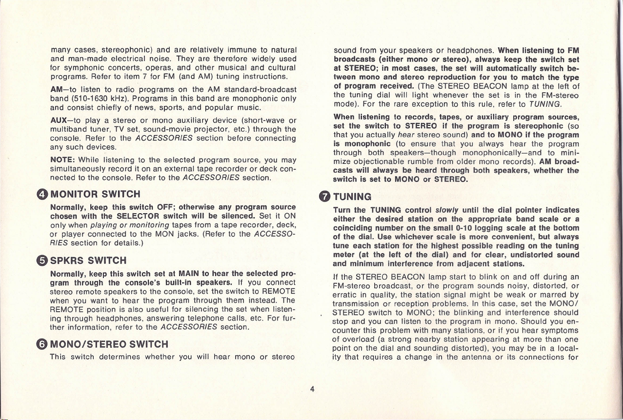
MONITOR SWITCH
Normally, keep this switch OFF; otherwise any program source
chosen with the SELECTOR switch will be silenced. Set it ON
only when
playing
or
monitoring
tapes from a tape recorder, deck,
or player connected to the MON jacks. (Refer to the
ACCESSO-
RIES
section for details.)
o
SPKRS SWITCH
Normally, keep this switch set at MAIN to hear the selected pro-
gram through the console's built-in speakers. If you connect
stereo remote speakers to the console, set the switch to REMOTE
when you want to hear the program through them instead. The
REMOTE position is also useful for silencing the set when listen-
ing through headphones, answering telephone calls, etc. For fur-
ther information, refer to the
ACCESSORIES
section.
o
MONO/STEREO SWITCH
This switch determines whether you will hear mono or stereo
sound from your speakers or headphones. When listening to FM
broadcasts (either mono
or
stereo), always keep the switch set
at STEREO; in most cases, the set will automatically switch be-
tween mono and stereo reproduction for you to match the type
of program received. (The STEREO BEACON lamp at the left of
the tuning dial will light whenever the set is in the FM-stereo
mode). For the rare exception to this rule, refer to
TUNING
When listening to records, tapes, or auxiliary program sources,
set the switch to STEREO if the program is stereophonic (so
that you actually
hear
stereo sound) and to MONO if the program
is monophonic (to ensure that you always hear the program
through both speakers-though monophonically-and to mini-
mize objectionable rumble from older mono records). AM broad-
casts will always be heard through both speakers, whether the
switch is set to MONO or STEREO.
TUNIN
Turn the TUNING control
slowly
until the dial pointer indicates
either the desired station on the appropriate band scale or a
coinciding number on the small 0-10 logging scale at the bottom
of the dial. Use whichever scale is more convenient, but always
tune each station for the highest possible reading on the tuning
meter (at the left of the dial) and for clear, undistorted sound
and minimum interference from adjacent stations.
If the STEREO BEACON lamp start to blink on and off during an
FM-stereo broadcast, or the program sounds noisy, distorted, or
erratic in quality, the station signal might be weak or marred by
transmission or reception problems. In this case, set the MONO/
STEREO switch to MONO; the blinking and interference should
stop and you can listen to the program in mono. Should you en-
counter this problem with many stations, or if you hear symptoms
of overload (a strong nearby station appearing at more than one
point on the dial and sounding distorted), you may be in a local-
ity that requires a change in the antenna or its connections for
4
---
I
I
Ii
I,
\
I
1066 FISHER RADIO CORPORATION All Rights Reserved
III
U()I'VI{I<111
(c) www.fisherconsoles.com

TRANSISTOR FM-AM MULTIPLEX RECEIVER
o
88 90 92 94 96 98 00 102 104 106 107108
'M
• 0 •
r
i •
u • o • n _ • n _ n _
I: • .. _
53 55 60 65 70 80 0 100 110120 140 160
AM
••••• 0 ••••• O_C
"""1"".""1""1.",1,,,,), •• ,1,,,,",,,,1,
,.\""1,"'61",1"""."1,,,,8,,,,1,
"0,,,,1""'0
I ,; ; ; : ; I
TUNING
MUTING MONIIOR
'0'
MONO l/EMOTE
OH
ON
FMAUTO AM
0
0
0
°
°c
' C)"'
r ,
I .' -, I .'
, 8
3 3 3 3 3 3
AC·Of:
to·
.
.
..
.
.
5 5 5 5 5 5
VOlUME BALANCE
SIHEO
MAIN
ON Off
- BASS
+
- TREBLE
+
SelECTOR
Figure 1. Control Panel of the Console
5
(c) www.fisherconsoles.com
reliable reception. Please refer to
FM ANTENNAS
in the
ANTEN-
NAS
section of this manual. Similarly, if you encounter consist-
ently poor reception on the AM band, refer to AM
ANTENNAS
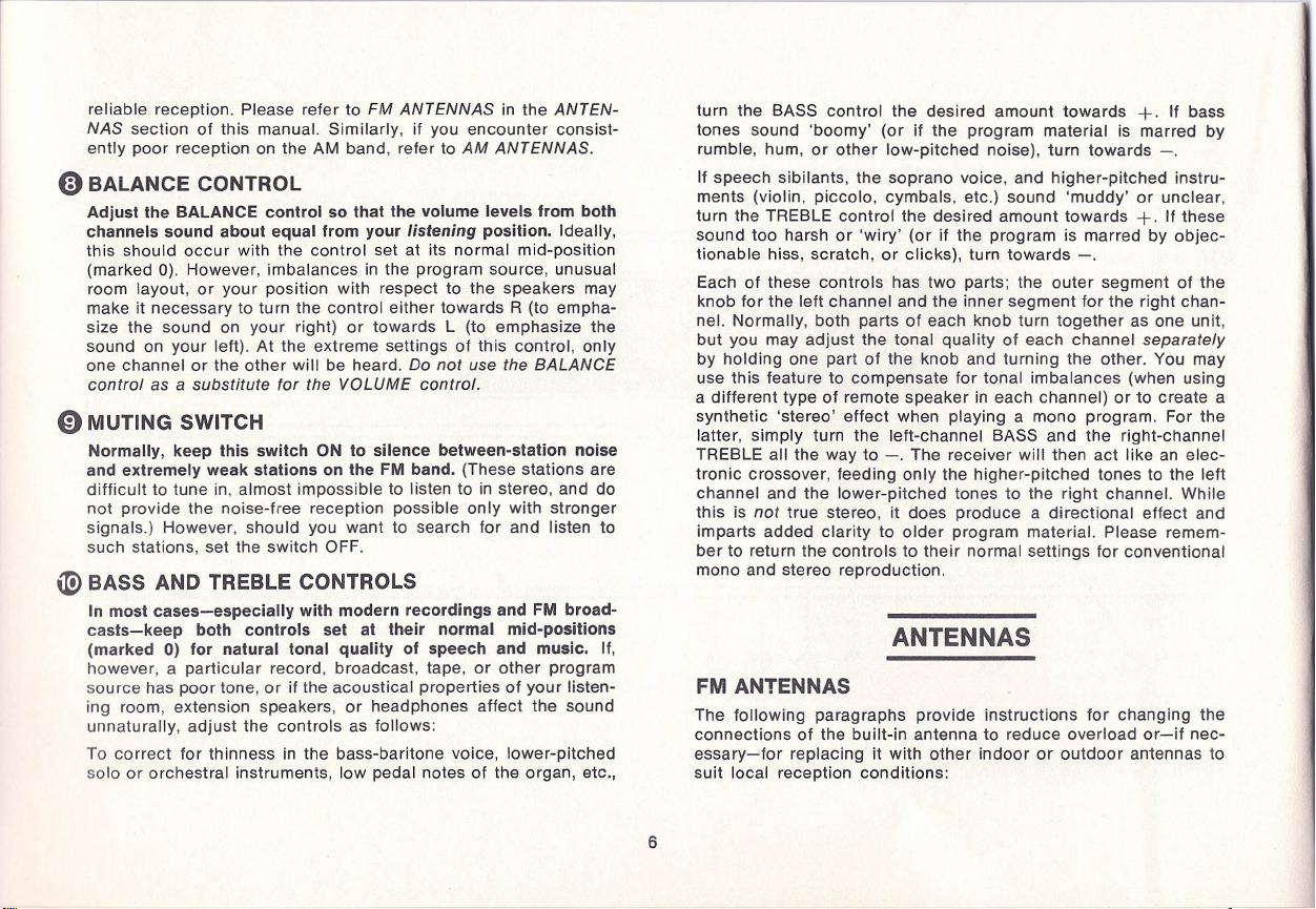
BALANCE CONTROL
Adjust the BALANCE control so that the volume levels from both
channels sound about equal from your
listening
position. Ideally,
this should occur with the control set at its normal mid-position
(marked 0). However, imbalances in the program source, unusual
room layout, or your position with respect to the speakers may
make it necessary to turn the control either towards R (to empha-
size the sound on your right) or towards L (to emphasize the
sound on your left). At the extreme settings of this control, only
one channel or the other will be heard.
Do not use the
BALANCE
control
as a
substitute for the
VOLUME
control
MUTING SWITCH
Normally, keep this switch ON to silence between-station noise
and extremely weak stations on the FM band. (These stations are
difficult to tune in, almost impossible to listen to in stereo, and do
not provide the noise-free reception possible only with stronger
signals.) However, should you want to search for and listen to
such stations, set the switch OFF.
BASS AND TREBLE CONTROLS
In most cases-especially with modern recordings and FM broad-
casts-keep both controls set at their normal mid-positions
(marked 0) for natural tonal quality of speech and music. If,
however, a particular record, broadcast, tape, or other program
source has poor tone, or if the acoustical properties of your listen-
ing room, extension speakers, or headphones affect the sound
unnaturally, adjust the controls as follows:
To correct for thinness in the bass-baritone voice, lower-pitched
solo or orchestral instruments, low pedal notes of the organ, etc.,
turn the BASS control the desired amount towards
+.
If bass
tones sound 'boomy' (or if the program material is marred by
rumble, hum, or other low-pitched noise), turn towards -.
If speech sibilants, the soprano voice, and higher-pitched instru-
ments (violin, piccolo, cymbals, etc.) sound 'muddy' or unclear,
turn the TREBLE control the desired amount towards
+.
If these
sound too harsh or 'wiry' (or if the program is marred by objec-
tionable hiss, scratch, or clicks), turn towards -.
Each of these controls has two parts; the outer segment of the
knob for the left channel and the inner segment for the right chan-
nel. Normally, both parts of each knob turn together as one unit,
but you may adjust the tonal quality of each channel
separately
by holding one part of the knob and turning the other. You may
use this feature to compensate for tonal imbalances (when using
a different type of remote speaker in each channel) or to create a
synthetic 'stereo' effect when playing a mono program. For the
latter, simply turn the left-channel BASS and the right-channel
TREBLE all the way to -. The receiver will then act like an elec-
tronic crossover, feeding only the higher-pitched tones to the left
channel and the lower-pitched tones to the right channel. While
this is
not
true stereo, it does produce a directional effect and
imparts added clarity to older program material. Please remem-
ber to return the controls to their normal settings for conventional
mono and stereo reproduction.
NTENN S
FM ANTENNAS
The following paragraphs provide instructions for changing the
connections of the built-in antenna to reduce overload or-if nec-
essary-for replacing it with other indoor or outdoor antennas to
suit local reception conditions:
6
-
I·
l
J
'.
I
i
i
I
• .:(11 1 11111111 1111111
I IllllI'R RADIO CORPORATION All Rights Reserved
(c) www.fisherconsoles.com
\
f
\I
-v
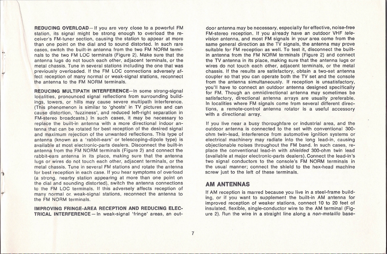
REDUCING OVERLOAD-If
you are very close to a powerful
FM
station, its signal might be strong enough to overload the re-
ceivers FM-tuner section, causing the station to appear at more
than one point on the dial and to sound distorted. In such rare
cases, switch the built-in antenna from the two
FM
NORM termi-
nals to the two
FM
LOC terminals (Figure 2). Make sure that the
antenna lugs do not touch each other, adjacent terminals, or the
metal chassis. Tune in several stations including the one that was
previously overloaded. If the
FM
LOC connections adversely af-
fect reception of many normal or weak-signal stations, reconnect
the antenna to the
FM
NORM terminals.
REDUCING MULTIPATH INTERFERENCE-In
some strong-signal
localities, pronounced Signal reflections from surrounding build-
ings, towers, or hills may cause severe multi path interference.
(This phenomenon is similar to ghosts in TV pictures and can
cause distortion, fuzziness , and reduced left-right separation in
FM-stereo broadcasts.) In such cases, it may be necessary to
replace the built-in antenna with a more directional indoor an-
tenna that can be rotated for best reception of the desired signal
and maximum rejection of the unwanted reflections. This type of
antenna (known as a rabbit-ears or telescoping-dipole type) is
available at most electronic-parts dealers. Disconnect the built-in
antenna from the
FM
NORM terminals (Figure 2) and connect the
rabbit-ears antenna in its place, making sure that the antenna
lugs or wires do not touch each other, adjacent terminals, or the
metal chassis. Tune in several
FM
stations and rotate the antenna
for best reception in each case. If you hear symptoms of overload
(a strong, nearby station appearing at more than one point on
the dial and sounding distorted), switch the antenna connections
to the
FM
LOC terminals. If this adversely affects reception of
many normal or. weak-signal stations, reconnect the antenna to
the
FM
NORM terminals.
IMPROVING FRINGE-AREA RECEPTION AND REDUCING ELEC-
TRICAL INTERFERENCE -
In weak-signal fringe areas, an out-
door antenna may be necessary, especially for effective, noise-free
FM-stereo reception. If you already have an outdoor
VHF tele-
vision
antenna, and most
FM
signals in your area come from the
same general direction as the TV signals, the antenna may prove
suitable for
FM
reception as well. To test it, disconnect the built-
in antenna from the
FM
NORM terminals (Figure 2) and connect
the TV antenna in its place, making sure that the antenna lugs or
wires do not touch each other, adjacent terminals, or the metal
chassis. If the results are satisfactory, obtain a two-set antenna
coupler so that you can operate both the TV set and the console
from the antenna simultaneously. If reception is unsatisfactory,
youll have to connect an outdoor antenna designed specifically
for FM. Though an omnidirectional antenna may sometimes be
satisfactory, directional antenna arrays are usually preferable.
In localities where FMsignals come from several different direc-
tions, a remote-control antenna rotator is a useful accessory
with a directional array.
If you live near a busy thoroughfare or industrial area, and the
outdoor antenna is connected to the set with conventional 300-
ohm twin-lead, interference from automotive ignition systems or
electrical machinery may radiate into the long lead-in, causing
objectionable noises throughout the
FM
band. In such cases, re-
place the conventional lead-in with
shielded
300-ohm twin lead
(available at major electronic-parts dealers). Connect the lead-in s
two signal conductors to the console s
FM
NORM terminals in
the usual manner; connect the shield to the hex-head machine
screw just to the left of these terminals.
AM ANTENNAS
If AM reception is marred because you live in a steel-frame build-
ing, or if you want to supplement the built-in AM antenna for
improved reception of weaker stations, connect 10 to 20 feet of
insulated, flexible, single-conductor wire to the AM terminal (Fig-
ure 2). Run the wire in a straight line along a
non-metallic
base-
7
-,
(c) www.fisherconsoles.com
rPHoN°l
HIGH
LOW
L
R
UX
LOW
UX
HIGH
L
RCDR
L
MaN
L
AM
..
,,"''''
"'"
",.
".""',
" ".'.
R
ld
@3
250W MAX
L
R
R R R
III
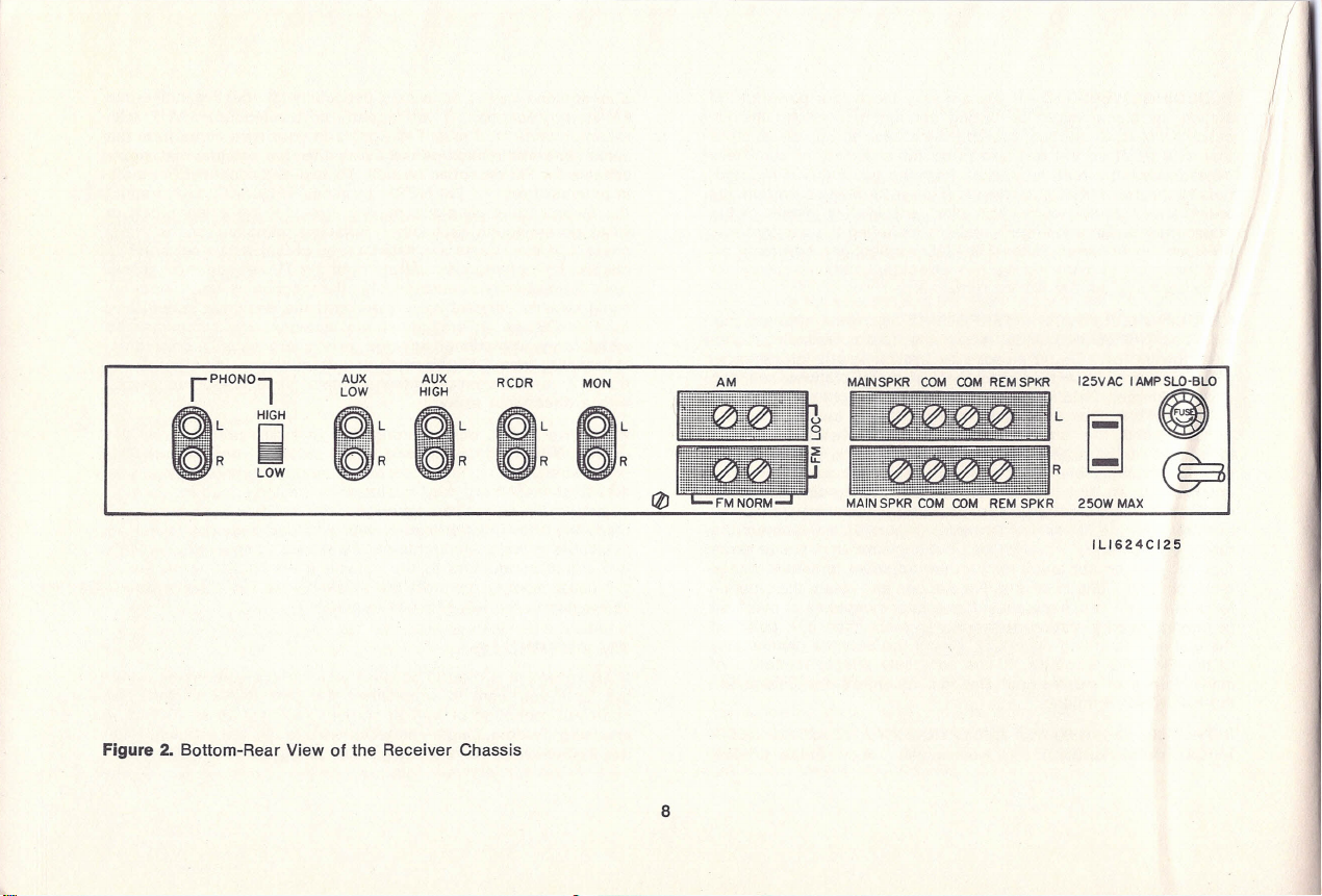
Figure 2
Bottom-Rear View of the Receiver Chassis
II!!
IlllfVIW 1111 III
ILl624CI25
8
IISllrR RADIO CORPORATION All Righls Hoscrvca -
(c) www.fisherconsoles.com
fl
board or under a rug. In some cases, reception may be further
improved by draping the wire out a window or by connecting it to
an outdoor whip or rod antenna.
CCESSORIES
HE DPHONES
For private listening from all program sources, you may plug a
pair of FISHER headphones (or other similar high-quality low- or
medium-impedance devices) into the PHONES jack on the control
panel. FISHER headphones are available from- your dealer, who
will assist you in the installation of several pairs, if desired.
When using the headphones for the first time, turn the VOLUME
control to minimum
before
plugging in the phones. Readjust the
VOLUME control for a comfortable
headphone
listening level and
use this setting for future reference. If you are presently not using
remote speakers, set the SPKRS switch to REMOTE to shut off
the console's speakers. (If you
are
using remote speakers and
still wish to silence all speakers when usinq the phones, your
dealer can provide you with an external switch for this purpose.)
CAUTION: Do not leave the headphones plugged in when playing
the speakers at high volume levels; the large amounts of audio
power required by the speakers at these levels can overload and
damage the phones.
WIDE-SURROUND SPE KERS
To enhance audible left-right separation when listening to stereo
program sources, you may connect a pair of FISHER WS-2 WIDE-
SURROUND' speakers to the console. These speakers-working
in conjunction with the console's speaker systems-will augment
the stereo sound pattern to a startling degree. (They are equally
effective in monophonic operation as welL) Further details about
the WS-2 speakers may be obtained from your dealer. To install
WS-2 speakers, proceed as follows:
CAUTION: Use WS-2 speakers
only
Do not connect WS-1's or
other types of speakers. They may cause serious damage to the
receiver circuits.
(1) Turn off the console and disconnect its power cord from the
electrical outlet.
(2) Place the speakers to the right and left of the console as de-
scribed in the WS-2 Operating Instructions.
(3) Connect the speakers to the WS jacks at the bottom-rear of
the console. Make sure that the speaker to the left of your
listening
position goes to the L jack while the speaker to your right goes
to the R jack.
(4) Connect the power cord to the electrical outlet and turn on
the console.
STEREO REMOTE SPE KERS
The REMOTE SPKR and adjacent COM terminals at the bottom
rear of the receiver (Figure 2) provide convenient means for con-
necting a pair of remote extension speakers. This arrangement
will enable you to enjoy stereo sound in another room of your
home when you set the SPKRS switch to REMOTE.
CAUTION: Make sure that each extension speaker's rated impe-
dance is at
least
4 ohms; a lower value may cause severe over-
load and distortion. (Look near its connecting terminals or in
its instruction book for the value or, if necessary, consult your
dealer.)
(1) Turn off the console and disconnect its power cord from the
electrical outlet.
(2) Place both speakers against a wall or on a shelf in the remote
listening area so that they face your selected listening position.
(c) www.fisherconsoles.com
Make sure that they are equidistant from you, no more than
10
to
15
feet apart (to prevent exaggerated stereo effects) and as
close as possible to ear level (for maximum clarity). Later on, you
can determine optimum locations on the basis of listening tests.
(3)
If the speakers are each
50
feet or less from the console, use
the cables supplied with the speakers or 'ordinary No.
18
two-con-
ductor lamp cord or antenna twin-lead for the connections. For
longer distances, use heavy-duty cable (at least No.
16 .
Cut two
cables to the desired length but leave some slack in case you
want to change speaker locations slightly. Strip about half an inch
of insulation from both ends of each conductor and twist the bare
wires to gather up loose strands. Look for some sort of marking
on each cable that distinguishes one conductor from another: a
distinctive color, stripe, or raised ridge on one of the insulators,
a thread under one of the insulators, or a different color for each
wire. This will help you to 'phase' the speakers in step
4.
(4) Connect the speaker at the left of your
listening
position to the
L (upper) terminal strip, making sure that its COM, GND, C, G, or
black terminal goes to the receiver's appropriate COM terminal
while its 4 OHMS, 8 OHMS,
16
OHMS, or red terminal goes to
the appropriate REMOTE SPKR terminal. Connect the speaker at
your right to the R (lower) terminal strip in the same manner.
Both speakers must be connected the same way ('in phase') for
correct stereo perspective and good bass response. Check that
the bare wires at the ends of the cables do not touch each other,
adjacent terminals, or the chassis.
(5) Connect the power cord to the electrical outlet and turn on
the console. Set the SPKRS switch to REMOTE and the MONO/
STEREO switch to MONO and playa record or FM program. If
the deep bass tones sound normal, the speakers are in phase, if
they sound weak or 'tinny', the speakers are out of phase; in this
case, turn off the console and carefully reverse the connections
at
one
of the speakers. Turn on the console and listen for normal
bass.
I III' I/IIIIII 1111111Illlll1l HAlliO COrll'ORATION All Iliel osmv=
(6) Set the MONO/STEREO switch to STEREO and playa
stereo
record or FM program. Experiment with speaker placement until
you find the permanent location that best suits your personal
tastes and listening conditions.
UXILI RY PROGR M SOURCES
You may increase the versatility of your console by playing an
additional mono or stereo program source through its AUX LOW
or AUX HIGH jacks (Figure
2 .
Moreover, if the extra source nor-
mally plays through its own low-fidelity speakers and amplifiers,
playing it through the console instead will improve its sound qual-
ity noticeably.
The auxiliary source may be an AM short-wave or multiband
tuner or receiver, the audio output of a TV set or sound-movie
projector, an electronic organ, or any other similar device so
long
as
it has at least one medium-or high-impedance output jack pro-
viding about 410
mV
to
2.5
volts of signal.
This type of jack is
often marked CATHODE FOLLOWER, LINE OUTPUT, EXTERNAL
AMPLIFIER
not
EXTERNAL SPEAKER), TAPE RECORDER, or the
like. If the device does not have the required jack, a qualified
service technician can install one and, if necessary, add provi-
sions for switching off its built-in speakers. If the device is an
AC/DC
or 'transformerless' type, make sure that the technician
eliminates shock hazard and hum caused by a 'hot' (electrically
unisolated) chassis. If you are in doubt about the safety charac-
teristics of the device, do
ot
connect it to the console.
Please note that you may use the AUX LOW
or
AUX HIGH jacks
but not both sets of jacks at the same time. The following proce-
dure gives instructions for determining which set of inputs to use:
(1) If the auxiliary device is monophonic (single channel), connect
its single output jack to the console's AUX LOW L jack; use a
shielded cable with the appropriate connector at each end. If the
auxiliary device is stereophonic, it will have
two
such output jacks,
one with the additional marking LEFT, L, A, or 1 and the other
10
7
i
(
\:
\
(c) www.fisherconsoles.com
with the marking RIGHT, R, B, or 2. Using two shielded cables,
connect the left output to the consoles AUX LOW L jack and
the right output to the AUX LOW R jack.
(2) Connect the auxiliary device s power cord to a standard elec-
trical outlet. Keep the power cord as far as possible from all
shielded cables.
(3) Turn on the auxiliary device. Set the consoles SELECTOR
switch to AUX. If the auxiliary device is monophonic, set the
consoles MONO/STEREO switch to MONO; if the device is
stereophonic, set the switch to STEREO. Adjust the consoles
VOLUME control for a comfortable listening level.
(4) Turn the console s SELECTOR switch back and forth between
AUX and FM AUTO and compare the relative volume levels of the
two program sources; they should be approximately equal
with-
out you having to readjust the
VOLUME
control drastically each
time you switch.
If the auxiliary device has any controls that affect
auxiliary volume as heard through the
console,
adjust them, if
necessary, to equalize the volume levels.
(5) If you can t reduce auxiliary volume sufficiently in step 4, or
if the auxiliary program sounds distorted on loud passages, switch
the connection(s) at the rear of the console from AUX LOW to
AUX HIGH. (Make sure that the left and right cables go to the
correct jacks.) Once again, turn the SELECTOR switch back and
forth between AUX and FM AUTO and make any possible adjust-
ments on the auxiliary device until the volume levels are about
equal. Adjust all other console controls as usual.
TAPE RECORDERS, DECKS, AND PLAYERS
The console has provisions for connecting an external tape
recorder or tape deck so that you may record any program source
to which you are listening and then play
back
the recording (or
any previously recorded tape) through the console at your con-
venience. If you wish playback
only
(of commercially prerecorded
tape), you may connect a tape player (having self-contained pre-
amplifiers) instead of the recorder or deck. In any event, the tape
unit may be a reel, cartridge, or cassette type.
CONNECTING THE TAPE UNIT-Use the following instructions
and Figure 2 to connect the tape unit to the console.
When con-
necting
a
player, ignore step 1.
(1) If the recorder or deck is monophonic (single channel), it may
have a single high-level recording input marked HIGH LEVEL,
LINE INPUT, PHONO, P.U., GRAM, or the like. Using a shielded
cable with the appropriate connector at each end, connect this
input to the console s RCDR L jack. If the recorder or deck
is equipped to make stereo recordings, it will have
two
such high-
level inputs, one with the additional marking LEFT, L, A, or 1 and
the other with the marking RIGHT, R, B, or 2. Using two shielded
cables, connect the left input to the console s RCDR L jack
and the right input to the console s RCDR R jack. Never con-
nect the console to any input(s) on the tape unit marked MIC.,
MICROPHONE, RADIO, or DIODE; the resultant recordings will
be severely overloaded and distorted.
(2) If the recorder, deck, or player is monophonic (single channel)
it may have a single playback output marked CATHODE FOL-
LOWER, LINE OUTPUT, MONITOR, EXTERNAL AMPLIFIER
not
EXTERNAL SPEAKER), or the like. Using a shielded cable with
the appropriate connector at each end, connect this output to the
consoles MON L jack. If the tape unit is equipped for stereo
playback, it will have
tw
such playback outputs, one with the
additional marking LEFT, L, A, or 1 and the other with the mark-
ing RIGHT, R, B, or 2. Using two shielded cables, connect the left
output to the console s MON L jack and the right output to the
consoles MON R jack.
(3) Connect the tape units power cord to a standard electrical
outlet. Keep the power cord as far as possible from any shielded
cables that connect to the console.
11
(c) www.fisherconsoles.com

RECORDING AND MONITORING - Use the following instructions
as a general guide to recording (and - if your recorder is properly
equipped as described in step
3-
to monitoring the tape while
recording). The tape unit's Instruction Manual will provide speci-
fic recording instructions.
(1)
As usual, choose the desired program source with the con-
sole's SELECTOR switch;
the source to which you are listening
is the source that will be recorded.
If both the program Source
and the tape unit are stereophonic (and you intend to make a
stereo recording), set the receiver's MONO/STEREO switch to
STEREO. If the program source or tape
unit
(or both) are mono-
phonic, or if you want to record a stereo source on a stereo
machine
monophonically,
set the MONO/STEREO switch to
MONO. This will blend the signal from a stereo source into a
complete, balanced mono signal; it will also assure that signals
from a mono Source are heard through both channels.
(2) Follow the tape unit's Instruction Manual for specific record-
ing instructions. The SELECTOR and MONO/STEREO switches
are the only console controls that have any effect on the re-
cording; you may therefore adjust all other controls in the usual
manner to suit your personal tastes and listening conditions.
(3) If you are absolutely certain that your tape unit has
true
tape-
monitor facilities (different circuits and heads for recording than
for playback), you may monitor the tape - while recording _ to
compare its sound quality with that of the original program mate-
rial from which it is being derived. To do this, alternate the
console's MONITOR switch between OFF (to hear the original
program material as usual) and ON (to hear the same material,
a fraction of a second later, as
it sounds on tape .
You may
repeat this as often as you like without affecting or interrupting
tho recording process in any way. When you've finished record-
Ing, remember to set the MONITOR switch OFF; otherwise, any
program chosen with the SELECTOR will be silenced.
PLAYBACK - To play back tapes from your recorder, deck, or
player, simply set the console's MONITOR switch ON. If the tape
is stereophonic, set the console's MONO/STEREO switch to
STEREO; if either the tape or tape unit is monophonic, set the
switch to MONO. Adjust all other console controls in the usual
manner to suit your personal tastes. When you've finished playing
tapes through the console, remember to set the MONITOR switch
OFF; otherwise, any other program source chosen with the
SELECTOR switch will be silenced.
NOTE: If the tape unit is stereophonic and you wish to listen to a
monophonic tape that has more than one track recorded on it,
the tape unit must have track-selection facl/ities (to prevent play-
back of more than one track at a time); otherwise, an external
track-selector switch must be used. To obtain a diagram of such
a SWitch, write to: Mr. Richard Hamilton, Customer Relations
Department, Fisher Radio Corporation, 11-40 45 Road, Long
Island City, New York 11101.
DYN MIC
SPACEXPANDER®
The FISHER Model K-10 OYNAMIC SPACEXPANDER ' is a unique
reverberation device that can be used in conjunction with this
console to recreate the acoustical environment of a large concert
hall or theater in your listening room. Further details about this
device may be obtained at your dealer. To connect a SPACE-
XPANDER to the console, proceed as follows:
(1)
Install the SPACEXPANDER in a suitable location as described
in its Instruction Manual.
(2) Connect
one
of the SPACEXPANDER's channel A INPUTS
to the console's RCDR L jack.
(3) Connect
one
of the SPACEXPANDER's channel B INPUTS to
the console's RCDR R jack.
NOTE: If you had to disconnect a tape recorder or deck from the
console in steps 2 and 3 to accommodate the SPACEXPANDER,
reconnect the recorder'S high-level inputs to the SPACE}wAND-
12
--
f
I
\
[iP l!lItlll 1111111I
111111
It ItAll11l
(lOIIPOllA'IION 1I1I1 IOhlo
Il080,Voti
-
(c) www.fisherconsoles.com
ERs
extra
channel A and B INPUTS. This will permit you to
record from the console while still using the SPACEXPANDER.
(The recordings, however, will not have reverberation since this
effect is added
after
the point at which the recorder is connected.)
Refer to the SPACEXPANDER manual for details.
(4) Connect the SPACEXPANDER s channel A OUTPUT to the
consoles MaN L jack.
(5) Connect the SPACEXPANDER s channel B OR C OUTPUT to
the consoles MaN R jack.
NOTE: If you had to disconnect a tape recorder, deck, or player
from the console in steps 4 and 5 to accommodate the SPACE-
XPANDER-and you still wish to play tapes through the console
- connect the output(s) of the tape unit to the consoles AUX
LOW or AUX HIGH jacks (if they are presently not in use) and
use the AUX position of the SELECTOR switch; this will permit
tape playback but not monitoring. As an alternative, you may
obtain a switchbox that will permit you to feed the outputs of
either the tape unit or the SPACEXPANDER to the consoles MaN
jacks. This type of switch is available at many electronic-parts
dealers.
(6) Set the consoles MONITOR switch ON and keep it in this posi-
tion whenever you use the SPACEXPANDER. When the SPACE-
XPANDER is turned off or disconnected, set this switch OFFj
otherwise, all program sources (except tape) played through the
console will be silenced. Adjust all other console controls in the
usual manner and operate the SPACEXPANDER as described in
its Instruction Manual.
MAINTENANCE
CAUTION: Turn off the console and disconnect its power cord
from the electrical outlet whenever instructed to do so in the
following procedures. Do
ot
attempt any maintenance not listed
in this section. For further service, consult your dealer.
PRESERVING THE CONSOLE S FINISH
Your console s fine-grain surfaces and rich satin finish are indi-
cations of the care and craftsmanship that have gone into its
construction. To preserve its appearance, we recommend that
you dust the console regularly and that you polish it occasionally
with a cream-type product such as OZ or GUARDSMAN.
CLEANING THE CONTROL PANEL
The beautiful gold-bordered control panel will retain its color and
brilliance permanently. However, it is possible that, over a period
of time, a film from atmospheric contamination may dull the sur-
faces. Simply use a soft,
freshly laundered
cloth moistened with
plain lukewarm water
and the panel will look new again. Do not
use any houseold or industrial cleaning agents or any cloth that
has been used to apply such agents.
CLEANING THE DIAL GLASS
(1) Turn off the console and disconnect its power cord from the
electrical outlet.
2) Gently
pull each control knob upwards and off its control shaft.
Do not attempt to remove the rocker switches.
(3) The control panel is held to the rest of the receiver chassis by
hex nuts on some of the control-shaft bushings. Remove the hex
nuts and lift off the panel.
(4) If there are two foam-cushion strips fastened to the retaining
clips at the ends of the dial glass, detach them from the clips.
(5) Loosen (do not remove) the screws that hold the dial-glass
retaining clips. Swing the clips aside and lift off the dial glass.
(The glass is held from behind by adhesive rubber strips; it may
therefore be necessary to apply a gentle prying force at the ends.)
3
(c) www.fisherconsoles.com

6) Remove dust with a soft, dry, lint-free cloth. If you wish to clean
more thoroughly, moisten the cloth with
plain lukewarm water
and
wipe the glass back and forth gently until it is clean and free of
streaks. Do not use any household or industrial cleaning agents;
they may damage the markings on the glass.
7) Replace the dial glass. Make certain to reset it in its original
position by placing it firmly against the
Iront lelt-hand
corner
of the plastic end frame. Swing the retaining clips back into
place and tighten the retaining-clip screws.
8) Replace the foam-cushion strips if removed previously),
control panel, hex nuts, and control knobs by reversing the pro-
cedures in steps
through 4. Connect the power cord to the elec-
trical outlet and turn on the console.
REPL CING DI L L MPS
The tubular dial lamps are spring-clip mounted at the ends of the
dial glass under the control panel. Should they burn out, you may
obtain exact replacements Part No. 1-50441-1) from your author-
ized FISHER dealer or from: Parts Department, Fisher Radio
Corporation, 11-40 45 Road, Long Island City, New York 11101.
Remove the control panel and replace the lamps as follows:
1) Turn off the console and disconnect its power cord from the
electrical outlet.
2) Gently
pull each control knob upwards and off its control shaft.
Do not attempt to remove the rocker switches.
3) The control panel is held to the rest of the receiver chassis by
hex-nuts on some of the control-shaft bushings. Remove the hex
nuts and lift off the panel.
4) Gently pull the burned-out lamp out of its clip and snap the
replacement lamp into place. Make sure that the
unpainted
side
of the lamp faces
towards
the edge of the dial glass.
5) Replace the control panel, hex nuts, and control knobs by
reversing the procedures in steps
and 3. Connect the power
cord to the electrical outlet and turn on the console.
SERVICING OTHER L MPS
The STEREO BEACON and tuning-meter lamps under the dial
glass and the pilot lamp near the base of the console are long-
lite devices that should not require replacement in normal use.
However, in the rare event that they should, do
not
attempt to
replace them yourself; they are
not
customer serviceable. Consult
your dealer or a qualified service technician.
REPL CING THE PHONOGR PH STYLUS
The stylus assembly is an integral part of the color-coded plastic
block at the front of the pickup cartridge. Should it be necessary
to replace a worn or damaged LP-stereo stylus, use this color as
a guide in obtaining an exact replacement gold block with brush,
Part No. G3511). To play old 78-RPM shellac records, you will
need an additional, interchangeable stylus with a larger tip blue
block, Part No. G3509). Either stylus may be purchased from:
Parts Department, Fisher Radio Corporation, 11-40 45 Road,
Long Island City, New York 11101. To replace or interchange styli,
proceed as follows:
1) If the console is on, turn down the VOLUME control to pre-
vent objectionable noises while changing the stylus.
2)
Unlock the pickup tone) arm from its rest clip and raise the
arm slightly;
do not lorce it.
3) Grasp the plastic block between the tips of the thumb and
forefinger of your free hand and
gently
pull it away from the main
body of the pickup cartridge. Insert the new stylus in its place
and lock the pickup arm in its rest.
CAUTION: Never play LP, LP-stereo, or 45-RPM records with the
78-RPM stylus blue block); the larger stylus tip will damage the
14
(c) www.fisherconsoles.com
fine-groove records. Always make sure that the appropriate
stylus is in place
before
playing records.
REPLACING THE POWER FUSE
The power fuse at the rear of the console protects it against
abnormal power-line surges and overloads. If the set fails to oper-
ate when plugged in and turned on or if it suddenly becomes com-
pletely inoperative while playing (i.e., all dial and pilot lamps go
off, turntable stops, and both channels are silent regardless of
program source), the fuse may have blown.
NOTE:
Before attempting to replace the fuse, make sure that other
factors aren t causing these symptoms. Check that the AUTO-
MATIC SHUTOFF switch is OFF when you are not using the rec-
ord player as the program source. Also make sure that the power
cord is firmly in the electrical outlet. If these measures don t
clear up the malfunction, proceed as follows:
(1) Turn off the console and disconnect its power cord from the
electrical outlet.
(2) The power fuse is in the black receptacle marked 1 AMP SLO-
BLO at the bottom-rear of the receiver chassis (Figure 2). Turn the
fuseholder cap counterclockwise (in the direction of the arrow on
the cap) until it disengages from the receptacle and remove the
fuse from the cap.
(3) The spare fuse supplied with the console has a short spiral coil
of wire inside its glass envelope (identifying it as a slow-blow
type). One of its metal ends is marked
1A
Use only this fuse (or
an exact commercial equivalent) as a replacement.
(4) Insert the replacement fuse in the fuse cap. Push the cap into
the receptacle and turn it clockwise (against the direction of the
arrow on the cap) until it is firmly in place. Connect the power
cord to the electrical outlet and turn on the console.
CAUTION: If the console still does not operate or if it becomes
inoperative within a short time do not attempt to replace the
fuse again. Consult your dealer or a qualified service technician.
5
(c) www.fisherconsoles.com
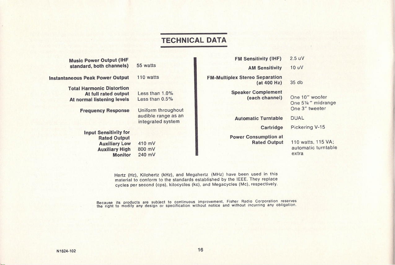
TECHNICAL DATA
Music Power Output IHF
I
FM Sensitivity IHF)
2.5 uV
standard, both channels)
55 watts
AM Sensitivity
10 uV
Instantaneous Peak Power Output
110 watts
FM-Multiplex Stereo Separation
at 400 Hz)
35 db
Total Harmonic Distortion
At full rated output
Less than 1.0%
Speaker Complement
At normal listening levels
Less than 0.5%
each channel)
One 10 woofer
One 5% midrange
Frequency Response
Uniform throughout One 3 tweeter
audible range as an
Automatic Turntable
DUAL
integrated system
Input Sensitivity for Cartridge
Pickering V-15
Rated Output Power Consumption at
Auxiliary Low
410 mV
Rated Output
110 watts, 115 VA;
Auxiliary High
800 mV automatic turntable
Monitor
240 mV extra
Hertz (Hz), Kilohertz (kHz), and Megahertz (MHz) have been used in this
material to conform to the standards established by the IEEE. They replace
cycles per second (cps), kilocycles (kc), and Megacycles (Mc), respectively.
Because its products are subject to continuous improvement, Fisher Radio Corporation reserves
the right to modify any design or specification without notice and without incurring any obllgation.
N1624-102
6
(c) www.fisherconsoles.com
.•r ,;i!! r !iilIli 'l1l'"
i
u
I I
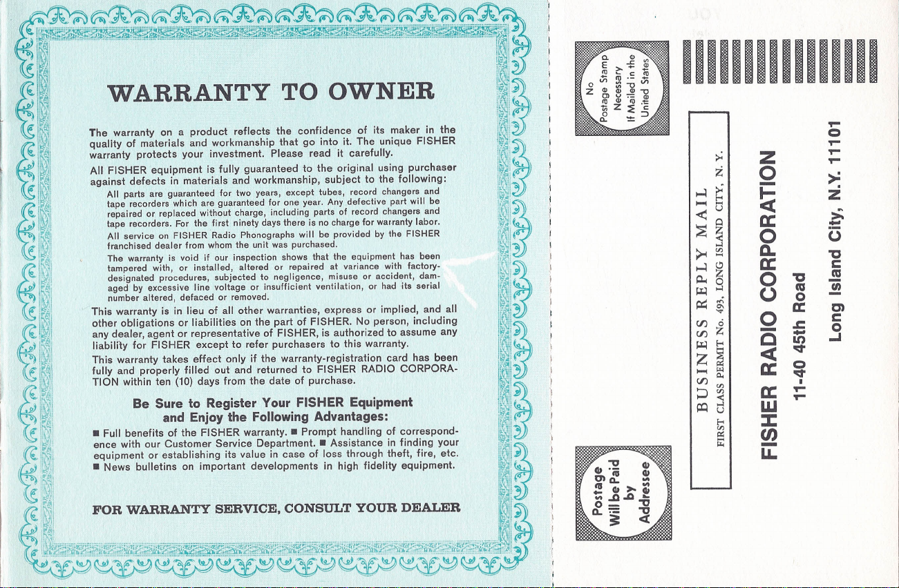
WARRANTY TO OWNER
i !
'I·'
Tho warranty
0'
a product reflects tho confidence of It, maker " tho
ltl'
i
I
e.
li
quality of materials and workmanship that go into it. The unique FISHER
11i;
I
warranty protects your investment. Please read it carefully.
[[Wi
I ,!!
All FISHER equipment is fully guaranteed to the original using purchaser
i :i,
I
.I
against defects in materials and workmanship, subject to the following:
11iX1i
jl
All parts are guaranteed for two years, except tubes, record changers and
It; :"Oj
-'6\
tape recorders which are guaranteed for one year. Any defective part will be
17;
1..\1.1.
repaired or replaced without charge, including parts of record changers and
I,l.•.
t..•.'•..
\.,ii.:,j
\.'l1,1\
tape recorders. For the first ninety days there is no charge for warranty labor.
!W: :
I
I
All se vice on FISHER 'Radio Phonographs will be provided by the FISHER
r !i
j,
franchised dealer from whom the unit was purchased.
i ;"':;!
''6\'
The warranty is void if our inspection shows that the equipment has been
l;;'
l
j.l.•
1
tampered with, or installed, altered or repaired at variance with factory-
'\'0\.
:' ,i
designated procedures subjected to negligence misuse or
accident,
dam-li f,
I
.·;j.·,
aged by excessive line voltage or insufficient ventilation, or had -its serial
l!i'I''',1
I );I
number altered, defaced or removed.
.t i
, , This warranty is in lieu of all other warranties, express or implied, and all
17. 1
1'. ).'1.1
other obligations or liabilities o the part of FI HER. N? person, including
l.{.\J'\;I.!.'
\.'l1,j
any dealer, agent or representative of FISHER,
IS
authorized to assume any
!'I'.• '
I I'
liabilily for FISHER except to refer purchasers to this warranty.
I i
." .1,1'
This warranty takes effect only if the warranty-registration card has been
I:l.
':i
l.
1r1'
fully an roperly filled out and returned to FISHER RADIO CORPORA-
't 1
, TION Within ten (10) days from the date of purchase,
. !
i" '
Be Sure to
egister
Your. FISHER Equipment
j l
; 'I'
and EnjOy the Following Advantages:
i i
, h
.); _ Full enefits of the FISHER warranty. - Prompt handlinq ?f orr spond-
I i
.iI
ence With our Customer Service Department. - ASSistanceIn finding your
;7 :
1...
.Ji.
equipment or establishing its value in case of I.oss.thro gh.theft, f.ire, etc.
1",.:f.n.c.'lI;;.;l.
" _ News bulletins on Important developments In high fidelity equipment. I¥!;;'
. II'
;i i
t ·
Il 1
FOR WARRANTY SERVICE, CONSULT YOUR DEALER
[ !
t
I I
I
,\1 . . . __ _ .. _. ... . _ .. .
i
'<111
\1:iI',:
lli,",IIII':
", ,'I'II','.1,1 'I',l': "II,'I'II' H 1 ,.::t!I :::t.j: ,,:ed!:"';Ii;/t,l';.
"tl;,' 'II'
',II,:I' J!:'.
II II'I'II'.:
""i,
1'1":
01
II,'I'II' '
Itl,,·I"I',r
11;0,I"I' 'II,
'II':.
,II,II'II':"""";'I\,j
ill 1 ::.
ai",
'I
1,'11,,1
;1,1"'I_ 'H Ih
::'';;' IIl Ik I "::::w'' J.I!l.J"
u'
Idl J" 1,IiIoJ ,"
Idll,J
I
1,I!!oJ'
I
I,I"' ,
lJII" '
I.I ,,' ". I I I ' ;.J."I
IIIUUIIIIUUI
-
I
1
z
•...•t:
-<
u
>-c
c,
0
>-i
'q>
CJ
0
CJ Z
f-<
Z
....•
CJ
c..
I:Q
:s
u
f-<
en
""
I
.•...
0
Z
.•...
.•...
0
.•...
-
;>.:
!;;:
Z
a::
0
-
c,
(3
a::
"C
0
C
"C
CU
0
CU
.
0
0
a:
C)
-
.c c
C
-
0
It)
..J
<C
"=t
a::
0
"=t
a::
I
.•...
W
.•...
:I:
UJ
-
LL
(c) www.fisherconsoles.com

iJr
PROTECT YOUR PURCHASE
PI,ease complete and return this
'¥ARRANTY CARD
\ PLEASE PRINT
Founder and President
Fisher Radio Corporation
FIRST NAME INITIAL
THE MAN BEHIND THE PRODUCT
S HOME ADDRESS
STATE
AVERY FISHER
DATE OF PURCHASE
Twenty-seven years ago, Avery Fisher introduced Americas first high fidelity
radio-phonograph. That instrument attained instant recognition, for it opened a
new era in the faithful reproduction of records and broadcasts. Some of its features
were so basic that they are used in all high fidelity equipment to this day. One of
these models is now in the permanent collection of the Smithsonian Institution as
an example of the earliest high fidelity instruments commercially available in this
country.
The engineering achievements of Avery Fisher and the world-wide reputation of
his products have been the subject of descriptive and biographical articles in
Fortune, Time, Pageant, The New York Times, Life, Coronet, High Fidelity, Esquire,
The Atlantic, and other publications. Benefit concerts for the National Symphony
Orchestra in Washington and the Philadelphia Orchestra, demonstrating recording
techniques, and the great advances in the art of music reproduction, used FISHER
high fidelity instruments both for recording and playback, to the enthralled audi-
ences. FISHER equipment formed the key part of the high fidelity demonstration
at the American National Exposition in Moscow, July 1959. FISHER FM and FM-AM
tuners are the most widely used by broadcast stations for monitoring and relay
work, and by research organizations-under conditions where absolute reliability
and maximum sensitivity are a must.
The FISHER instrument you have just purchased was designed to give you many
years of pride and enjoyment. If you should desire information or assistance on
the installation or performance of your FISHER, please write directly to Avery
Fisher, President, Fisher Radio Corporation, Long Island City 1, New York.
Name of
Dealer _
City State _
I
irst
heard of THE FISHER through (check one box only)
o
Advertising
Friend
Dealer
If purchased because of advertising. please give name of
publication: _
Have you seen The Fisher Handbook?
Yes
No
I chose THE FISHER because: _
What I think of my FISHER equipment: _
o
You may quote me.
I also own these additional hi-Ii units and speakers: _
WARRANTY VOID UNLESS COMPLETED AND RETURNED
WITHIN 10 DAYS AFTER DATE OF PURCHASE
(c) www.fisherconsoles.com
Table of contents


