THE GALLERY COLLECTION Solano Guide

1
Solano
PREMIUM ELECTRIC STOVE
INSTRUCTION MANUAL AND USER GUIDE
PLEASE READ THESE INSTRUCTIONS CAREFULLY BEFORE INSTALLATION
AND OPERATION. KEEP THEM IN A SAFE PLACE FOR FUTURE REFERENCE
REV A 05/22

2
Before installation, check that all parts included are undamaged. If the appliance is
damaged, check with the supplier before installation and operation. If the supply cord is
damaged, it must be replaced by the manufacturer, its service agent or similarly qualified
persons in order to avoid a hazard.
CAUTION: In order to avoid a hazard due to the inadvertent resetting of the thermal cut-out,
this appliance must not be supplied through an external switching device, such as a timer, or
connected to a circuit that is regularly switched on and off by the utility.
Do not use the appliance outdoors.
Do not use the appliance in the immediate surroundings of a bath, a shower or a swimming
pool.
Do not leave the appliance unattended during use.
Do not run the mains cable under carpet, rugs, etc.
Do not locate the appliance immediately below a fixed socket outlet or connection box.
Do not install the appliance using an extension cord.
Do not install the appliance in an open flue.
Do not insert any objects into the appliance.
Do not operate the appliance near flammable materials or fire.
Do not clean the appliance with abrasive cleaners.
Do not use this fire in rooms that have explosive gas in them (for example petrol), or if you
are using solvents, glue, aerosol spray or in flammable paints, as these may catch fire.
Do not use this appliance in small rooms when they are occupied by persons not capable of
leaving the room on their own, unless constant supervision is provided.
Do switch off and unplug the appliance from the main socket when not in use or before
cleaning and maintenance.
Do keep the appliance away at least 1 meter from furniture, curtains or other combustible
material when in use.
Do ensure the plug remains easily accessible after installation of the appliance.
Do use this appliance on a horizontal and stable surface.
IMPORTANT INFORMATION

3
CAUTION: Some parts of this product can become very hot and cause burns. Particular
attention has to be given where children and vulnerable people are present.
Children of less than 3 years should be kept away from the products unless continuous
supervised. Children aged from 3 years and less than 8 years shall only switch on/off the
appliance provided that it has been placed in its intended normal operating position and they
have been given supervision or instruction concerning use of the appliance in a safe way and
understand the hazards involved. Children aged from 3 years and less than 8 years shall not
plug in, regulate and clean the appliance or perform user maintenance.
NOTE: A dedicated, properly fused 13 Amp circuit is required, rated for the appropriate
voltage (230-240V). An isolation switch should also be incorporated in cases where the
product plug is inaccessible after installation.
NOTE: This appliance must be earthed.
WARNING! Construction and wiring (including electrical safe zones) must comply with local
building codes and other applicable regulations to reduce the risk of fire, electric shock and
injury to persons.
WARNING! To reduce the risk of fire, electric shock or injury to persons, always use a licensed
electrician.
WARNING! Information for authorized person or service center only: A non-rewireable plug
fitted with a 13A fuse is supplied. Should the fuse or plug need replacing, and you are
competent to do so, it must be replaced with a 13A fuse or plug being 13A BS1363A approved.
WARNING: In order to avoid overheating, do not cover the heater or air vents located on the
appliance or obstruct the air circulation around the appliance.
IMPORTANT INFORMATION

4
HEAT OUTPUT
VALUE
UNIT
Supply Voltage
230-240 (AC/50Hz)
V
Max.Power Consumption
2000
W
Power for Flame Effect
25
W
Power for Ambient Light Kit
9.6
W
HEAT OUTPUT
SYMBOL
VALUE
UNIT
Nominal Heat Output
Pnom
1.8-2
kW
Minimum Heat Output
Pmin
1
kW
Maximum Continuous Heat Output
Pmax
2
kW
AUXILIARY ELECTRICITY CONSUMPTION
At Nominal Heat Output
elmax
12.5
W
At Minimum Heat Output
elmin
12
W
In Standby Mode
elSB
2.1
W
TYPE OF HEAT OUTPUT / ROOM TEMPERATURE CONTROL
YES / NO
Single stage heat output and no room temperature control
NO
Two or more manual stages, no room temperature control
NO
With mechanic thermostat room temperature control
NO
With electronic room temperature control
YES
Electronic room temperature control plus day timer
YES
Electronic room temperature control plus week timer
YES
OTHER CONTROL OPTIONS
YES / NO
Room temperature control, with presence detection
NO
Room temperature control, with open window detection
YES
With distance control option
YES
With adaptive start control
YES
With working time limitation
NO
With black bulb sensor
NO
ITEMS
MAIN CONTROL BOARD
WiFi MODULE
REMOTE CONTROL
Hardware
RC01-067A01-V0.0
WR3 V1.0
RF455H-V0.0
Software/Logic
TC01-067A01-V1.0
/
RCS20-V1.0
Frequency
FSK 433.92MHz/2.4GHz
2.4GHz
FSK 433.92MHz
Maximum Transmit Power
10mW
100mW
10mW
TECHNICAL INFORMATION

5
Carefully position the stove upside down, ensuring that
the surface underneath is free from debris, to avoid
scratches or other potential damage to the stove top. A
soft carpet of towel will be ideal. Offer each of the legs
into position so that the two locating pegs on each leg
fits securely into the corresponding holes on the
underside of the stove. Finally secure using 4 x Screw
A. When finished, carefully return the stove to an
upright orientation.
CONTENTS
ASSEMBLY
LEGS

6
Open the stove door and position the handle against the front of the door.
Take 2 x Screw B and push from behind, through the holes in the stove door, using a screwdriver to secure to the
handle on the other side.
DOOR HANDLE

7
FUEL SETUP
Place Log E into the centre of the fuel bed
area.
Distribute the Embers around the fuel bed
then scatter an amount of Vermiculite
Granules on top of the embers. It is not
necessary to use all the embers and
vermiculite supplied.
Locate the two tabs on either side of the
door opening and slot the Log Bar into the
stove. The log bar should sit firmly down
onto the bottom edge of the opening.
LOG A
LOG B
LOG C
LOG D
LOG E
STEP 2
STEP 3
STEP 1

8
-
FUEL SETUP CONTINUED
Place Log C into the stove as shown on the
image above. The left side of the log should
be positioned towards the rear, left side of
the fuel bed. The right side of the log should
rest on the centre of Log E.
Place Log D into the stove as shown on the
image above. The left side of the log (there
is charring on the left side of the log) should
rest on the centre of Log E. The right side of
the log should be positioned towards the
front, right side of the fuel bed.
Place Log B into the stove as shown on the
image above. The left side of the log should
be positioned towards the front, left side of
the fuel bed. The log should be angled
towards the rear of the fuel bed, resting
upon Log C.
Place Log A into the stove as shown on the
image above. The right side of the log
should be positioned towards the rear, right
side of the fuel bed. The log should be
angled towards the front of the fuel bed,
resting upon Log D .
STEP 4
STEP 5
STEP 6
STEP 7

9
The stove can be operated conveniently in 3 different ways: manually, via the remote control handset or via the
dedicated iOS/Android app.
The manual control buttons are located inside the stove on the panel directly behind the stove door.
Each time a button is pressed on the appliance or on the remote control an audible beep is emitted. To turn off this
feature hold your finger on the Preset Mode button (on the appliance) for 3 Seconds.
Wifi On/Off
Press to turn wifi on or off. An illuminated LED on the button indicates that wifi is turned on. Hold button for 3
seconds to enter device pairing mode.
Standby
Turns on the appliance with the last used settings without any heat. Places the appliance into standby mode with all
features turned off.
Heat Mode
1 press = cool blow. 2 press = low heat setting. 3 press = high heat setting. 4 press = no heat/no cool blow.
Preset Mode
Press repeatedly to cycle through the 6 fire preset modes (+3 user defined presets if programmed).
Ensure that 2 AAA batteries are inserted into the remote control handset. The battery power level is indicated by
the column of bars to the right side of the temperature display when the appliance is in standby mode. 5 bars
indicates the batteries are full, 1 bar indicates the batteries are empty and need to be replaced immediately.
Remote Control Setup
Press and hold the Standby button on the appliance until you hear two beeps, release the button. Press Standby
button on the remote control handset and you will hear one beep. The remote is connected with the appliance.
IMPORTANT: The remote control handset must be left in the same room as the appliance as it houses the
thermostat that regulates heat output.
Preset Mode
Heat Mode
Standby
Wifi On/Off
OPERATION
MANUAL CONTROL
REMOTE CONTROL

10
Button 1: Preset Mode
Repeatedly press to cycle through the 6 preset fire
Modes (+ 3 user defined presets if programmed).
On screen Pr.1 = Autumn Campfire
On screen Pr.2 = Ember Glow
On screen Pr.3 = Inferno
On screen Pr.4 = Noir
On screen Pr.5 = Fire & Ice
On screen Pr.6 = Nebula
On screen Pr.7 = User Preset
On screen Pr.8 = User Preset
On screen Pr.9 = User Preset
There are 3 preset slots allocated for the user to
Save personalised e-fire creations. Simply choose
the flame colour and brightness level, the fuel bed
colour and brightness level and fuel bed down light
colour and brightness level. One you have selected
your desired combination, press and hold the Preset
Mode button for 3 seconds until the LCD displays
Pr.7. Press –and + buttons to select a slot number
between 7-9. Press and hold the Preset Mode button
for 3 seconds to confirm the preset.
Button 2: Standby
Turns on the appliance with the last used settings
without any heat. Places the appliance into standby
mode with all features turned off.
Button 3&9: Minus & Plus
Use to navigate through different on-screen menus.
Button 4: Flame Speed
Press once to enter flame speed menu –SPd will show on the LCD screen. Press the plus and minus buttons to adjust
the flame speed. The flame speed is indicated on screen by bars –1 bar is the slowest setting; 5 bars is the fastest
setting.
Button 5: Flame Colour
Repeatedly press to cycle through flame colour menu. Whilst in the flame colour menu, press the plus and minus
buttons to increase and decrease the flame brightness - 1 bar is the dimmest setting, 5 bars is the brightest setting.
On screen FL.0 = Flame off
On screen FL.1 = Red
On screen FL.2 = Orange
On screen FL.3 = Yellow
On screen FL.4 = Green
On screen FL.5 = Light Blue
On screen FL.6 = Dark Blue
OPERATION CONTINUED

11
On screen FL.7 = Violet
On screen FL.8 = White
On screen FL.9 = Multi-colour change
Button 6: Fuel Bed Colour
Repeatedly press to cycle through fuel bed colour menu. Whilst in the fuel bed colour menu, press the plus and
minus buttons to increase and decrease the fuel bed brightness - 1 bar is the dimmest setting, 5 bars is the brightest
setting.
On screen Fb.0 = Fuel bed off
On screen Fb.1 = Red
On screen Fb.2 = Orange
On screen Fb.3 = Yellow
On screen Fb.4 = Green
On screen Fb.5 = Light Blue
On screen Fb.6 = Dark Blue
On screen Fb.7 = Violet
On screen Fb.8 = White
On screen Fb.9 = Multi-colour change
Button 7: Timer Mode
Repeatedly press to cycle through timer options. Select an amount of time for the appliance to operate then
automatically turn off. Choose between 0.5, 1, 2, 3, 4, 5, 6, 7, 8, 9 hours.
Button 8: Fuel Bed Down Light
Repeatedly press to cycle through fuel bed down light colour menu. Whilst in the fuel bed down light colour menu,
press the plus and minus buttons to increase and decrease the fuel bed brightness - 1 bar is the dimmest setting, 5
bars is the brightest setting.
On screen dL.0 = No illumination
On screen dL.1 = Red
On screen dL.2 = Orange
On screen dL.3 = Yellow
On screen dL.4 = Green
On screen dL.5 = Light Blue
On screen dL.6 = Dark Blue
On screen dL.7 = Violet
On screen dL.8 = White
On screen dL.9 = Multi-colour change
Button 10: Heater Mode
Press to cycle through the heat output options.
1 press: Co.A = Cool blow setting
2 press: H.Lo = Low heat setting
3 press: H.HI = High heat setting
4 press: no.H = No Heat
OPERATION
OPERATION CONTINUED

12
Whilst in heater mode after selecting low or high heat setting, press the –and + buttons to select the temperature
you want the room to reach. Note: if the room temperature is already higher than the temperature selected, the
heater will not activate. To switch between ℃/℉hold down the –and + buttons for 3 seconds.
Open Window Detection is an innovative eco feature that detects a rapid drop in room temperature caused by an open
window. The warning word "OPn" will be displayed on the screen and the heater will be turned off. If the room
temperature rises or the remote control is operated manually, the heater will return to its normal working state.
Button 11: Sound Effect
Press to open the open the sound effect menu.
1 press: S.on = Sound effect on
2 press: no.S = Sound effect off
Whilst in the sound effect menu, press the plus and minus buttons to increase and decrease the volume - 1 bar is the
quietest setting, 5 bars is the loudest setting.
Button 13: Ambient Lighting (if appliance is fitted with optional Ambient Lighting Kit)
Repeatedly press to turn on ambient lighting and cycle through the different colour options.
Button 14: Eco Mode eco
Press to activate Eco mode. This mode will reduce the brightness of all lighting modes and limit the heat output to
low setting, resulting in reduced energy consumption. Press the button a second time to exit Eco mode.
Visit your device app store (iOS or Android) to download the TUYA SMART APP. Once installed follow the procedure
below to pair the device with your appliance.:
Step 1. Start the app and click “Add Device” on screen. Select “Small Home Appliance” from the list, then select
“Heater (Wi-Fi)”.
Step 2. Ensure the appliance is powered on then press and hold the button on the appliance until you hear 3
beeps. At the same time the button will flash and the fuel bed will flash.
Step 3. Follow the instructions on the app to input your home network details. Note, your device must also be
connected to the same home network you wish to connect the appliance to.
Once connected you can fully control your appliance and also programme a weekly timer that features Adaptive
Start Control –a smart home device that gauges the current temperature of the room and anticipates the time
required to heat it to a desired temperature. When in weekly timer mode, the appliance will automatically
determine the time to turn on the heater to ensure that the set temperature is met at the time required (up to 45
minutes prior to the set time).
For further guidance, please consult the section ‘App Connection Guide’ on page 15.
OPERATION CONTINUED
APP CONTROL

13
This stove can be used with an LED mood lighting kit approved by Vision Fires –
The Solus Ambient Light Kit (available from your retailer). Other, non-approved
LED light kits must not be used as they may damage the appliance and invalidate
the warranty. The Solus Ambient Light Kit must only be used when connected
directly to the appliance using the pre- fitted connecting adaptor (this can be
found at the underside of the stove at rear of the heater enclosure, next to the
mains plug socket). The Solus Ambient Light Kit must not be adapted to be
operated independently of the appliance, such as modifying it to run on an
independent 240v supply.
The Solus Ambient Light Kit is supplied as a 3m LED strip with adhesive tape
backing, and a 2m extension cable (not illuminated).
IMPORTANT: ALWAYS DISCONNECT THE STOVE FROM THE POWER SUPPLY AND ALLOW TO COOL BEFORE
CLEANING.
Any repairs or maintenance should only be carried out by a suitably qualified competent person.
The appliance should be occasionally cleaned using a dry cloth. Do not use detergents, abrasive cleaners of furniture
polish.
To clean the glass, use a lightly damp cloth and ensure any moisture is dried fully using a lint free cloth.
Ensure that the heater vent is kept dust free by occasionally vacuuming the area using a brush attachment.
Resetting the Thermal Cut Out
The appliance is fitted with an Electronic Safety Control (E.S.C.). This is a safety device which switches off the fire if,
for any reason, the appliance overheats, e.g. when covered. If the heater stops operating while the flame effect
CLEANING & MAINTENANCE
TROUBLESHOOTING
IMPORTANT INFORMATION –AMBIENT LIGHT KIT
3m LED STRIP
2m EXTENSION CABLE

14
continues working normally, this indicates that the E.S.C. is in operation. The E.S.C. can only be reset after the
appliance has cooled down and the appliance has been reset. Re-setting of the E.S.C. procedure is as follows:
1. Switch off the appliance (Manual On/Off switch) and leave it off for approximately 10-15 minutes.
2. Remove any obstruction to the fan heater outlet or fan blades etc. Make sure that the power supply is disconnected
with the plug socket outlet while doing this.
3. Switch on the appliance and the E.S.C. will be reset.
4. Ensure that the appliance is functioning correctly. If the E.S. Control operates again, the appliance should be checked
by a competent electrician.
PROBLEM
POSSIBLE CAUSE
SOLUTION
Appliance will not turn on.
Problem with power supply.
Check that the appliance is plugged
in to the power supply and switched
on.
Check and replace fuse in the plug if
necessary.
Check that the main power switch
on the appliance is turned on.
Remote control does not work.
Batteries have expired.
Replace batteries.
Remote has de-synched with
appliance.
Ensure that the appliance is turned
on. Re-synch the remote by
pressing the -button and the +
button at the same time and holding
for 3 seconds.
No heat
Incorrect thermostat setting.
Increase the desired temperature
higher than the current room
temperature.
Overheating may have engaged the
E.S.C. feature.
See above for reset procedure.
Heat turns off before desired
temperature is reached.
Open window detection has
activated.
Check that any windows in the room
are closed.
Vision E-Line appliances come with a standard 1-year warranty (parts & labour) when purchased through an
authorised dealer. This can be extended for free to two years (parts only for year 2) by registering your appliance
within 60 days of purchase.
Visit www.visionfires.co.uk/warranty to register your appliance, activate the free warranty extension, or to see
details about the 6 year Premium Protect warranty package.
WARRANTY
TROUBLESHOOTING CONTINUED

15
To connect your applioance to the Vision E-Line Solus app you will need the following:
✓ A device running android or ios such as a tablet or smart phone
✓ Network within range of the fire
✓ Valid email address, which you are able to access for verification
Download the Tuya Smart app from your app store
Once downloaded, the TUYA icon will apear on your device’s home screen, you can now open this app by tapping the
icon.
Follow the directions in the app to create an account. A valid email address will be required to complete the account
set up process. Once your account is set up you will receive a number of permissions, please follow the on screen
prompts.
APP CONNECTION GUIDE
STEP 1 –DOWNLOAD THE TUYA SMART APP & CREATE ACCOUNT

16
Now you can begin the process of connecting your appliance to the app. At the home screen press the ‘Add Device’
button.
Once the password has been entered you will be presented with a checklist to ensure trouble free connection of
your appliance to the network. You may also be asked to allow location permissions, please read, and follow the
on-screen information.
APP CONNECTION GUIDE
STEP 2 –CONNECT YOUR APPLIANCE TO THE APP

17
After you have gone through the permissions you will then need to choose which device to pair, please select small
home appliances from the menu as shown below:
Now from the list of small home appliances select Heater (Wi-Fi). This will then prompt you to enter your Wi-Fi
password, ensure the correct network is selected enter your Wi-Fi password then press the next button.
APP CONNECTION GUIDE

18
Now the app will prompt you to reset the device. This is referring to placing your fire into pairing mode. Before
tapping next you will need to put your appliance into pairing mode. Ensure the fire is switched on then press and
hold the Wi-Fi button on your fire, located on the panel directly behind the stove door as shown below, until fuel bed
flashes red.
Once the fire is placed in pairing mode with a flashing red fuel bed, tap the next button on the app and choose the
Blink Quickly button this will then begin to search for the fire, when it has successfully paired the fire fuel bed will
display a solid green colour.
Flashing Red –In pairing
APP CONNECTION GUIDE

19
Please note, the fire fuel bed colour indicates the status of the fire when first initiating the pairing the fuel bed will
flash red. Once successfully paired the fuel bed will display green. If a flashing blue fuel bed appears check your
connection and repeat the pairing procedure.
On successful pairing you can now use the Vision E-Line app to control your appliance. Your appliance will now be
listed as a device in the Tuya home screen. Select the appliance to begin using the Vision E-line app. To turn the fire
on use the power button as highlighted in the illustraion below.
Flashing Red –In pairing
Solid Green –Successfully paired
Flashing Blue –Failed Pairing
APP CONNECTION GUIDE
STEP 3 –SUCCESSFUL PAIRING

20
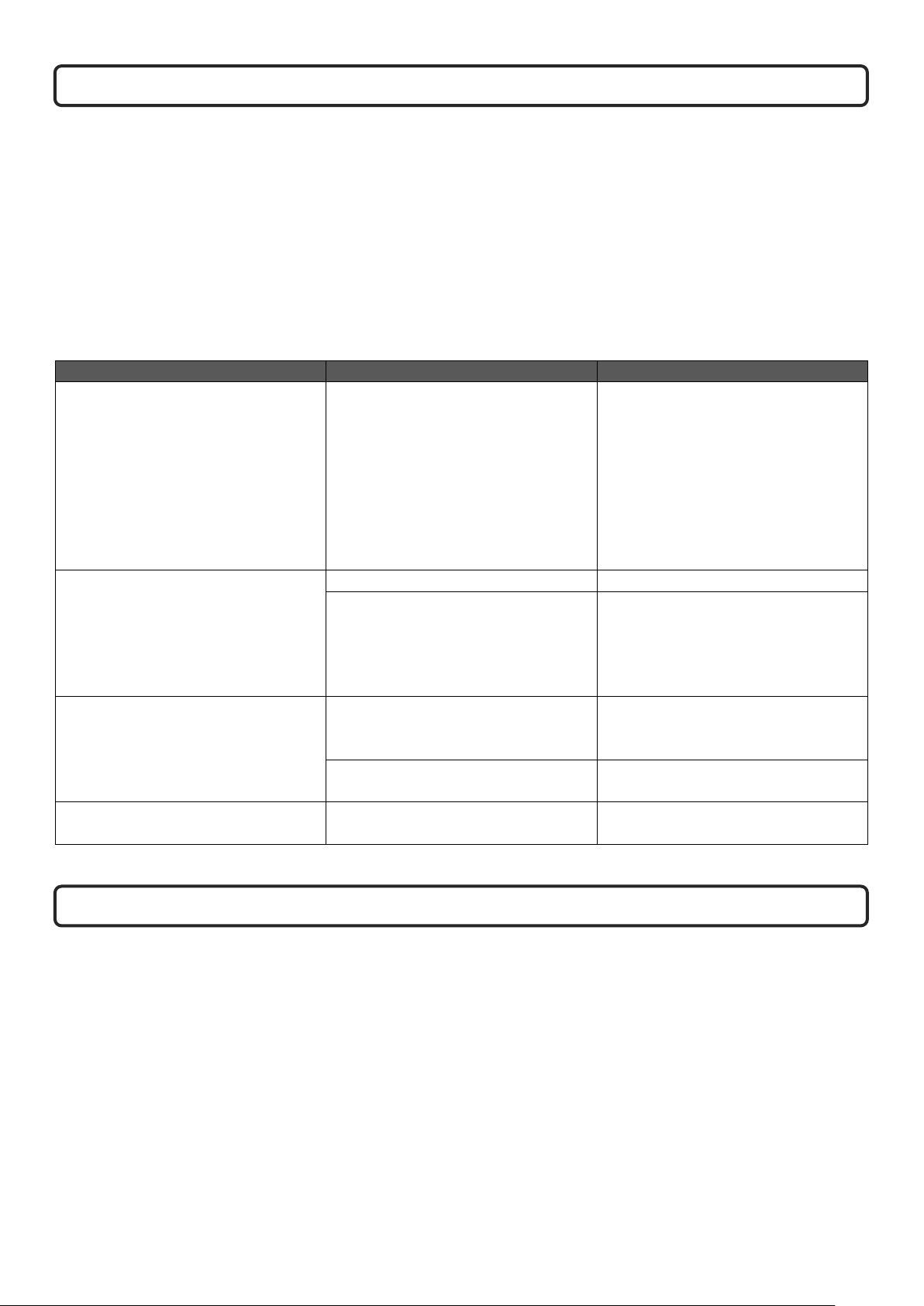
If you have trouble connecting, please check:
•Ensure your appliance is in standby mode
•Your appliance is in range of the network
•Your smartphone/tablet is connected to your home network
•Ensure the latest version of the app is installed on your phone or tablet
•Check your network has a good signal strength
If you are still experiencing issues, please uninstall the app from your device and reinstall then repeat the above
steps.
Advanced Wi-Fi Router Guidance
Wireless transmissions get weaker as you get further from your wireless router, they can also be disrupted by
general building fabrics, such as metal framework, walls & floors.
For the best possible connection to your Solus appliance, the location of your wireless router in relation to your
appliance is key:
•If there are certain areas of your home where you find your signal drops, it may be due to a blockage.
•Large objects can often obstruct or interfere with a wireless connection, so it's best to keep your router off the
ground and away from larger items
•Steer clear from putting your router behind the sofa, inside a cabinet or behind a door - although it looks tidy,
if you are experiencing an issue this could be the cause a problem
•You should also keep electronics such as microwaves, lamps, speakers, TVs and monitors as far away from the
router as possible
If issues are encountered when trying to connect your appliance, our best advice would be to follow the below:
1. Check the location of the appliance in relation to the wireless router, are there any objects that may be causing
a problem with the signal?
2. Check if you are experiencing the same connection problem across other devices, you can do this by checking
their Wi-fi status. Typical devices to be checked would be your mobile phone, tablet, laptop, or even your TV.
3. Try adding a new device to your wireless network – this will verify that the wireless password & SSID are correct.
4. Are you using wireless extenders? If so, turn off all wireless extenders and add try adding a new device (a
mobile phone for example) in the same location as your wireless router. This confirms that your Wireless router
is accepting new devices without issue.
5. You could also try resetting the wireless router.
Tips and advice:
If the appliance is installed out of the range of your wireless network, the Wi-Fi signal will not be detected by the
appliance. It may be too far away from your router. You may need to purchase a signal booster to extend the range
of your home network. You can purchase a Wi Fi booster form any computer store, online or an electrical retailer.
How do I know if my Wi-Fi signal is strong enough or if the appliance is out of range?
Simply stand in front of the appliance holding the device in close proximity to the control panel, you will find this on
the front of the appliance. By using an existing device, that is already connected to the wireless network, this could
be a phone or tablet, and then see if the Wi-Fi indicator shows that you have signal? If the signal strength is not full,
it may indicate connectivity issue. If they are greyed out or only 1 or 2 bars are showing, then the signal strength of
your home network will need boosting, in order for your Tuya app to control the appliance.
APP CONNECTION TROUBLESHOOTING
Table of contents
Other THE GALLERY COLLECTION Stove manuals
Popular Stove manuals by other brands

Ravelli
Ravelli HRV 100 Touch instruction manual

Lennox Hearth Products
Lennox Hearth Products 775 Installation instructions manual

Warmland
Warmland PS45 Classic Series A Installation and operating instructions

Harman Stove Company
Harman Stove Company SF 3500A Installation and operating manual

Muskoka
Muskoka MES30BL-3 Phoenox manual

scandia
scandia Verdant LE owner's manual