Thinklogical SDI to HDMI Converter/Extender User manual

SDI to HDMI Converter and
SDI to HDMI Converter/Extender
Product Manual
Thinklogical, LLC
®
100 Washington Street
Milford, Connecticut 06460 U.S.A.
Telephone: 1-203-647-8700
Fax: 1-203-783-9949
www.thinklogical.com

SDI to HDMI Converter, Rev. C 2July, 2012
Extend Distribute Innovate
®
Copyright Notice
Copyright © 2012. All rights reserved. Printed in the U.S.A.
Thinklogical, LLC®
100 Washington Street
Milford, Connecticut 06460 U.S. .
Telephone: 1-203-647-8700
All trademarks and service marks are property of their respective owners.
Subject: SDI to HDMI Converter Product Manual
Revision: Rev C, July 2012

SDI to HDMI Converter, Rev. C 3July, 2012
Table of Contents
Preface 4
Conventions Used in this Manual 4
1 Introduction 4
1.1 Contents 4
1.2 Product Overview 5
2 System Features 6
2.1 General System Features 6
2.2 Technical Specifications 7
3 Connecting the SDI to HDMI Converter 8
3.1 RS-232 Pin Out 8
3.2 User Menu Configurations 8
4 Regulatory and Safety 16
4.1 Safety Requirements 16
4.1.1 Symbols Found on Product 16
4.2 Regulatory Compliance 16
4.2.1 North America 16
4.2.2 Australia & New Zealand 16
4.2.2.1European Union Declaration of Conformity 17
4.2.2.2Standards with which the Products Comply 17
4.2.3 Supplementary Information 18
4.2.4 Product Serial Number 18
5 How to Contact Us 19
5.1 Customer Support 19
5.1.1 Website 19
5.1.2 Email 19
5.1.3 Telephone 20
5.1.4 Fax 20
5.2 Product Support 20
5.2.1 Warranty 20
5.2.2 Our Address 21
Appendix A: Application Diagrams 22
Appendix B: Quick Start Guide 25
Appendix C: GUI 26

SDI to HDMI Converter, Rev. C 4July, 2012
PREFACE
About this Product Manual
This manual is divided into five sections: 1. Introduction, 2. System Features, 3. Connecting
the SDI to HDMI Converter, 4. Regulatory and Safety Compliance and 5. Customer &
Product Support. These are sub-divided to help you find the topics and procedures you are
looking for. This manual also contains Appendices.
Conventions Used in this Manual
As you read this manual you will notice certain conventions that bring your attention to important
information. These are Notes and Warnings. Examples are shown below.
Note: Important Notes appear in blue text preceded by a yellow exclamation
point symbol, like this.
A note is meant to call the reader’s attention to helpful information at a point in the text that is
relevant to the subject being discussed.
Warning! All Warnings appear in red text, followed by blue text, and pre-
ceded by a red stop sign, like this.
A warning is meant to call the reader’s attention to critical information at a point in the text that is
relevant to the subject being discussed.
1.Introduction
1.1. Contents
When you receive your Thinklogical
®
SDI to HDMI Converter, you should find the following items:
•SDI to HDMI Converter (SDC-000001) or
SDI to HDMI Converter/Extender (SDC-000001-LC)
•AC/DC adapter universal input 90-264 VAC – PWR-000022-R
•SDI to HDMI Converter product manual.

SDI to HDMI Converter, Rev. C 5July, 2012
1.2. Product Overview
The Thinklogical
®
SDI to HDMI Converter allows you to seamlessly convert a broadcast quality
SDI signal to HDMI. The unit is full SMPTE compliant, including the active loop out port.
FIGURE 1: Top View of SDI to HDMI Converter (P/N SDC-000001)
FIGURE 2: Top View of SDI to HDMI Converter/Extender (P/N SDC-000001-LC)

SDI to HDMI Converter, Rev. C 6July, 2012
2.System Features
2.1. General System Features
The Thinklogical
®
SDI to HDMI Converter allows users to seamlessly convert a broadcast
quality SDI signal to HDMI. The SDI to HDMI Converter is full SMPTE compliant, including
the active loop out port. The SDI to HDMI Converter/Extender has a fiber output that is fully
compatible with our Velocity line of receivers as well as our VX routers for a comprehensive
conversion and extension solution. Not only does it convert and scale video signals in real-
time, it also provides the highest quality images for professional audio-visual end users.
Each SDI to HDMI Converter system includes the following features:
Conversion/Scaling:
•Input: SD, HD, 3G SDI
•Output: 1920x1200p60, 1080p50, 1080p60, 720p50, 720p60, 576p50, 480p60.
•Fiber optic output compatible with Thinklogical Velocity Receivers
•SDI embedded audio conversion to HDMI output and compatible with Thinklogical
Velocity Receivers
•User Control via RS-232 and Ethernet
•SMPTE standards supported: 259M-C, 292, 424M, 425 level A and level B
•Active SMPTE compliant loop out port
•Automatic Video Input Detection
•Additional manual resolution selection via push buttons
Video Processor Features:
•Per pixel motion-adaptive video noise reduction- removes the white Gaussian noise
present in most types of video
•Content adaptive block and mosquito noise reduction- significantly reduces the blocking
and mosquito noise artifacts present in compressed video
•Advanced per-pixel, motion-adaptive, edge-adaptive 3D de-interlacing with support for
arbitrary film cadences- removes “jaggies” and “feathering” to produce smooth and clear
images
•Adaptive scaling- produces sharp and clean images and low or high resolutions
•Natural dept expansion- enhances details and sensation of depth for greater realism and
super resolution effect
•Adaptive contrast enhancement (ACE) brings out shadow detail without crushing mid-
tones or highlights
•Intelligent color remapping (ICR) enables vivid color without hue shifts and clipping while
maintaining accurate flesh tone
•Qdeo™ true color- a unique solution for using the full dynamic range of 10-bit and 12-bit
displays which eliminates contouring seen when viewing typical 8-bit consumer video

SDI to HDMI Converter, Rev. C 7July, 2012
2.2. Technical Specifications
Frame Rate Formats Supported:Progressive, Interlaced, PsF
Function Video Standards Supported Formats
SD-SDI SMPTE 259M PAL and NTSC
HD-SDI SMPTE 292M All standard HD-SDI compatible formats
3G SDI SMPTE 424M, 425M, Level A and B All SMPTE 425 level A and B compatible
formats
Storage Temperature
0 to 50 deg C , 5 – 95 % RH, non condensing
Power Supply Voltage
+5.0 VDC
DC Adapter
AC/DC adapter universal input 90-264 VAC
Power Consumption
With Velocity SFP: 9.5 Watts
Without Velocity SFP: 8.5 Watts
Operating Temperature and
Humidity
0 to 50 °C (32 to 122 °F); 5 to 95% RH, non-condens ing
Enclosure Dimensions
Height: 1.1” (27.94 mm)
Depth: 7” (177.80 mm)
Width: 5.375" (136.65 mm)
Weight
Actual Weight: 1 lb (0.45 kg)
Shipping Weight: 9 lbs (4.08 kg)
Complianc
e
Pending approvals for US, Canada, and European Union
SDI to HDMI Converter, Rev. C 8July, 2012
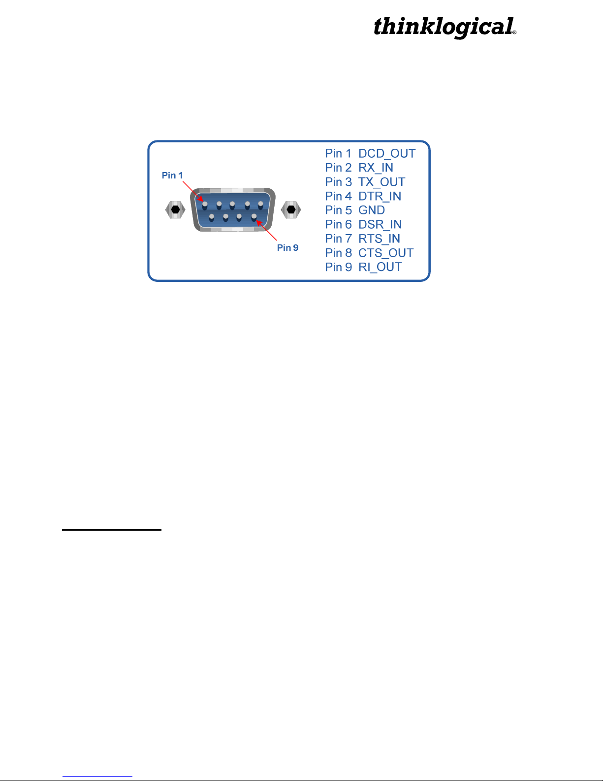
3. Connecting the SDI to HDMI Converter
3.1 RS-232 Pin Out
3.2
User Menu Configurations:
The IEX3 has many configuration options and this document will cover these options in detail.
Every configuration can be set regardless of the user interface (e.g. RS-232, RS-422, Front
Panel Display, Web Interface). There are a lot of status and configuration settings that can be
viewed but are not output to the Front Panel display due to the display limitations. The RS-232
and RS-422 interface menus will have an 'exit' option. Selecting this option will display the menu
items one level up. The SPACE bar will repeat the current menu and the ENTER key will return
the user to the top level menu. This document will be formatted similarly to the configuration
menus that are displayed on power-up.
The RS-232 setup and configuration is as follows:
•Use Hyperterm or similar type interface.
•Baud rate is 115200, 8 bits, no parity, 1 stop bit, no flow control
•Emulate VT-100 mode
MAIN USER MENU:
A: Set Input Select
B: Set Output Select
C: Video Processing Setup
D: Audio Info and Setup
E: User Config Setups
F: System Settings
G: System Information

SDI to HDMI Converter, Rev. C 9July, 2012
MAIN MENU:
A: Set Input Select
Note: A valid input must be applied in order for the configuration to be used.
a: Single Link Input
This option forces a re-configure of the unit. A valid signal needs to be present.
b: Enable Loop Output
This will enable the video signal applied to input 1 to be looped back out of the
IEX3. This is enabled as default.
c: Disable Loop Output
Turns off the BNC Loop output 1.
d: AUTO mode ON
Detects when a video source has changed format. On cable insertion, the unit
performs a re-configuration of the last known output setting with the new input.
e: AUTO Mode OFF
Turns off the AUTO mode.
MAIN MENU:
B: Set Output Select
Sets the output video resolution. A valid input video signal needs to be present.
a: 480p @ 60
b: 576p @ 50
c: 720p @ 50
d: 720p @ 60
e: 1080p @ 50
f: 1080p @ 60 (default)
g: 1920x1200p @ 60
MAIN MENU:
C: Video Processing Setup
a: Comp. Artifact Reducer
Selects menu for Component Artifact Reducer (CAR) video processing functions.
b: DeInterlacer
Selects the menus for the DeInterlacer (DEINT) video processing functions.
c: Noise Reducer
Selects the menus for the Noise Reduction (NR) video processing functions.
d: Picture Control
Selects the menus for Picture Control (PC) video processing functions.
e: Edge Enhancer
Selects the menus for Edge Enhancement (EE) video processing functions.
f: Color Management Unit
Selects menus for Color Management Unit (CMU) video processing functions.

SDI to HDMI Converter, Rev. C 10 July, 2012
g: Adapt. Contrast Enhancer
Selects the menus for the Adaptive Contrast Enhancer (ACE) video processing
functions.
h: 3D Control Menu
Selects the menu for output 3D processing formats.
MAIN MENU:
D: Audio Info and Setup
a: Enable Audio Output
Enables the embedded audio output from the selected input.
b: Disable Audio Output
Mutes all embedded audio output channels.
c: Get Audio Info Input
Get Audio information from BNC Input.
d: Set Audio Delay
Audio Delay range is from -50 - +50 in mS with the default being 0.
e: Get Audio Delay
The programmed Audio Delay in mS.
f: Get Audio Channel Cfg.
Get the audio channel mapping.
g: Assign Audio Channels
Configure input to output channel configuration.
MAIN MENU:
E: User Config Setups
a: Save Current Config
Saves the current system settings to the non-volatile Memory. Maximum of 20
characters for the record name.
b: Set Power On Config
This option will set the current configuration to the user in an accessible region of
flash. This configuration is restored during power up.
c: Restore Config Record
Recall any one of the current saved configuration records.
d: Restore Factory Config
By selecting this, the IEX3 will delete the stored power on configuration and will
re-configure to the factory default on the next power cycle (1080i @ 60 Hz).
Another way to achieve this is to hold down the front panel knob for a minimum
of 5 seconds during a power cycle.
e: Erase Record(s)
Erase a particular record or all records.

SDI to HDMI Converter, Rev. C 11 July, 2012
MAIN MENU:
F: System Settings
a: Ethernet Settings
Settings for the network interface.
Default Settings:
IP Address – 192.168.75.200
Mask – 255.255.255.0
Gateway – 0.0.0.0
b: Enable HDMI Output Video Mode
Enables the HDMI output to be in true HDMI mode.
c: Enable DVI Output Video Mode
Enable this option if the sink device is a true DVI monitor/projector.
d: Get Video Mode
This will return the current video mode.
MAIN MENU:
G: System Information
The following is used for retrieving information regarding current setup and signal
detection information. The 'Get Genlock Info' is not available for display on the Front
Panel. The 'Get Input X', 'Get Output Info' will display the signal format only on the Front
Panel whereas the other communications interfaces will display more verbose info.
a: Get Software Version
Displays the System’s software version number.
b: Get FPGA Version
Displays FPGA 1 version number
c: Get Linux Version
Displays version of software currently running on ethernet interface.
d: Get Local Temperature
Displays the temperature inside the box
e: Get Input Info
Displays Information about the video and embedded audio signal on BNC Input 1
f: Get Output Info
Displays Information about the video and embedded audio signal on BNC
Outputs
MAIN MENU:
C: Video Processing Setup
SUB-MENU:
a: Comp. Artifact Reducer
This feature is used to reduce compression artifacts that are caused by video com-
pression schemes such as MPEG2. Mostly used on YCbCr 4:2:2 interlaced or pro-
gressive input video.
a: Comp. Arti. Reducer EN
Enables the Compression Artifact Reducer.

SDI to HDMI Converter, Rev. C 12 July, 2012
b: Mosq. Noise Reducer EN
Enables the Mosquito (Ringing) Noise Reducer.
c: Block Noise Reducer EN
Enables the Block (8x8) Noise Reducer.
d: Non Std Block Noise Det EN
Enables the Non-Standard Block Detection.
e: Enable All CAR Blocks
Enables All the above (A,B,C,D) Noise Reduction Blocks.
f: Disable All CAR Blocks
Disables All the Noise Reduction Blocks.
MAIN MENU:
C: Video Processing Setup
SUB-MENU:
b: DeInterlacer
Selects the menu for the DeInterlacer (DEINT) video processing functions.
a: Deinterlacer BYPASS
Bypasses the deinterlacer (input is progressive).
b: Deint 2D VECTOR
Sets the Interlacer for 2D Vector mode (Interlaced input DEFAULT mode).
c: Deint 2D VECTOR AGGRES.
Sets the Interlacer for 2D Aggressive mode (Interlaced input).
d: Deint 3D FIXED
Sets the Interlacer for 3D fixed mode (Interlaced input).
e: Deint 3D Mo Adpt Vector
Sets the Interlacer for 3D Motion Adaptive Vector mode.
f: Deint 3D MA Vect Aggres
Sets the Interlacer for 3D Motion Adaptive Vector Aggressive mode.
g: Deint 3D MA Vect Linear
Sets the Interlacer for 3D Motion Adaptive Vector Linear mode.
h: DEINTERLACER DEFAULT
Sets the Interlacer for DEFAULT mode.
MAIN MENU:
C: Video Processing Setup
SUB-MENU:
c: Noise Reducer
Selects the menus for the Video Noise Reduction (NR) video processing functions.
Used mostly on YCbCr 4:2:2 Input video.
a: Noise Reducer DISABLE
Disables the Noise Reduction block.
b: Noise Reducer 2D
Sets the Noise Reducer for 2D (Spatial) mode.
c: Noise Reducer 3D Fixed
Sets the Noise Reducer for 3D Fixed (Temporal) mode.

SDI to HDMI Converter, Rev. C 13 July, 2012
d: Noise Reducer 3D Adapt
Sets the Noise Reducer for 3D Adaptive (Temporal) mode.
e: Noise Reducer Default
Sets the Noise Reducer for Default mode.
f: Noise Reducer Automatic
Sets the Noise Reducer for Automatic mode.
MAIN MENU:
C: Video Processing Setup
SUB-MENU:
d: Picture Control
a: Set All Levels Default
Restores Contrast, Brightness, Tint, Black, Color Temp levels to defaults.
b: Set Contrast Level
Enter the Contrast Level 0 to +10. The Default value is 10.
c: Set Brightness Level
Enter the Brightness Level -100 to +100. The Default value is 0.
d: Set Tint Level
Enter the Tint Level -180 to +180. The Default value is 5.
e: Set Black Level
Enter the Black Level 0 to +100. The Default value is 0.
f: Set Color Temperature
SUB MENU : Video Set Color Temperature Menu
a: Color Temperature NORMAL
Sets the color temp to 6500.
b: Set Color Temperature COOL
Sets the color temp to 8000.
c: Color Temperature WARM
Sets the color temp to 6000.
d: Color Temperature CUSTOM
Enter Color Temp Level 6000 to 8000 (Normal = 6500)
MAIN MENU:
C: Video Processing Setup
SUB-MENU:
e: Edge Enhancer
Selects the menus for Edge Enhancement (EE) video processing functions.
a: Edge Enhancer OFF
b: Edge Enhancer LOW
c: Edge Enhancer MED
d: Edge Enhancer HIGH

SDI to HDMI Converter, Rev. C 14 July, 2012
MAIN MENU:
C: Video Processing Setup
SUB-MENU:
f: Color Management Unit
Selects the menus for Color Management Unit (CMU) video processing functions.
a: Hue Saturation Menu
Video Hue Saturation Menu
a: Hue Saturation ENABLE
b: Hue Saturation DISABLE
c: Intelligent Saturation ENABLE
d: Intelligent Saturation DISABLE
e: Set HUE Saturation Level
f: Set HUE Global Sat. Level
g: ICR Advanced Menu
Note: Hue saturation needs to be enabled (selection ‘a’) in order for ‘Set
HUE Saturation Level’ (selection ‘e’) to be valid.
b: Qdeo True Color Menu
Video Qdeo Menu
a: Qdeo True Color OFF
b: Qdeo True Color SOFT
c: Qdeo True Color GENTILE
d: Qdeo True Color MEDIUM
e: Qdeo True Color HIGH
c: Film Grain Gain Menu
Video Film Grain Gain MENU
a: Disable Film Grain Gain
b: Set Film Grain Gain
Range is 0 - 255. Default is 0.
c: Set FGG Temporal Freq.
Range is 0 - 255. Default is 0.
d: Flesh Tone Correction
a: Set FTDC Preset Enable
b: Set FTDC Preset Level 1
c: Set FTDC Preset Level 2
d: Set FTDC Preset Level 3
e: Set FTDC Preset Level 4
f: Set FTDC Preset Level 5
g: Set FTDC Preset Level 6
h: Set FTDC Preset Disable
e: Set GAMMA Menu
a: GAMMA Disable
b: GAMMA 1.8
c: GAMMA 2.5
d: GAMMA S-Curve Light
e: GAMMA S-Curve Dark

SDI to HDMI Converter, Rev. C 15 July, 2012
MAIN MENU:
C: Video Processing Setup
SUB-MENU:
g: Adapt. Contrast Enhancer
Selects the menus for Adaptive Contrast Enhancer (ACE) video processing functions.
a: ACE PRESET OFF
b: ACE PRESET LOW
c: ACE PRESET MEDIUM
d: ACE PRESET HIGH
e: ACE PRESET RANGE 0-255
f: ACE PRESET RANGE 16-235
g: ACE Brightness Menu
a: Brightness DISABLE
b: Brightness DEFAULT
c: Brightness Taper Size
Enter Taper Size (16, 32, 64, 128, 256, 512).
d: Brightness Taper Side
Enter Taper Side Select (1,2).
e: Brightness Enhancement
Enter Enhancement Level (1 - 15).
f: Brightness Threshold 1
Enter Threshold 1 Level (0 - 1023).
g: Brightness Threshold 2
Enter Threshold 2 Level (0 - 1023).
MAIN MENU:
C: Video Processing Setup
SUB-MENU:
h: 3D Control Menu
a: Left/Right Frame Menu
Menu to functions that will allow the zooming in of an incoming 3D side-
by-side signal and display one half as a 2D image (left eye or right eye).
b: Line-By-Line Output Menu
Select output format of a line-by-line signal.
c: Disable Line-By-Line Output
Turns off the line-by-line feature.
d: Side-By-Side Output Menu
Select output format of a side-by-side signal.
e: Disable Side-By-Side Output
Turns off the side-by-side feature.
f: Dual Stream Output Menu
Select output format of a dual stream signal.
g: Enable Adaptive Clock
Factory Use.
h: Disable Enable Adaptive Clock
Factory Use.

SDI to HDMI Converter, Rev. C 16 July, 2012
4.Regulatory and Safety
4.1 Safety Requirements
4.1.1 Symbols Found on Product
Markings and labels on the product follow industry-standard conventions. Regulatory markings
found on the products comply with requirements.
4.2 Regulatory Compliance
Thinklogical
®
products are designed and made in the USA. Our products have been tested by a
nationally recognized testing laboratory and found to be compliant with the following standards
(both domestic USA and many international locations).
4.2.1 North America
These products WILL comply with the following standards:
Safety
•ANSI/UL60950-1: 1
st
Edition (2003)
•CAN/CSA C22.2 No. 60950-1-03
Electromagnetic Interference
•FCC CFR47, Part 15, Class A
•Industry Canada ICES-003 Issue 2, Revision 1
4.2.2 Australia & New Zealand
This is a Class A product. In a domestic environment this product may cause radio interference,
in which case the user may be required to take adequate measures.

SDI to HDMI Converter, Rev. C 17 July, 2012
European Union
4.2.2.1 Declaration of Conformity
Manufacturers name and address:
Thinklogical, LLC
®
100 Washington Street
Milford, CT 06460 USA
Telephone 1-203-647-8700
Product name
SDI to HDMI Converter (Part number SDC-000001)
SDI to HDMI Converter/Extender (Part number SDC-000001-LC)
This product complies with the requirements of the Low Voltage Directive 72/23/EEC and
the EMC Directive 89/336/EEC.
4.2.2.2 Standards with which the Products Comply
Safety
•CENELEC EN 60950-1, 1
st
Edition (2001)
Electromagnetic Emissions
•EN55022: 1994 (IEC/CSPIR22:1993)
•EN61000-3-2/A14:2000
•EN61000-3-3:1994
Electromagnetic Immunity
•EN55024:1998 Information Technology Equipment-Immunity Characteristics
•EN61000-4-2:1995 Electro-Static Discharge Test
•EN61000-4-3:1996 Radiated Immunity Field Test
•EN61000-4-4:1995 Electrical Fast Transient Test
•EN61000-4-5:1995 Power Supply Surge Test
•EN61000-4-6:1996 Conducted Immunity Test
•EN61000-4-8:1993 Magnetic Field Test
•EN61000-4-11:1994 Voltage Dips & Interrupts Test

SDI to HDMI Converter, Rev. C 18 July, 2012
4.2.3 Supplementary Information
The following statements may be appropriate for certain geographical regions and might not
apply to your location.
Note: This equipment has been tested and found to comply with the limits for a
Class A digital device, pursuant to part 15 of the FCC Rules. These limits are
designed to provide reasonable protection against harmful interference when the
equipment is operated in a commercial environment. This equipment generates,
uses and can radiate radio frequency energy and, if not installed and used in
accordance with the instruction manual, may cause harmful interference to radio
communications. Operation of this equipment in a residential area is likely to
cause harmful interference in which case the user will be required to correct the
interference to radio communications at his own expense.
Note:This Class A digital apparatus complies with Canadian ICES-003 and has
been verified as being compliant within the Class A limits of the FCC Radio
Frequency Device Rules (FCC Title 47, Part 15, Subpart B Class A), measured to
CISPR 22: 1993 limits and methods of measurement of Radio Disturbance
Characteristics of Information Technology Equipment.
This Class A digital apparatus meets all requirements of the Canadian Interference-Causing
Equipment Regulations.
Cet appareil numerique de la classe A respecte toutes les exigencies du Reglement sur le
material brouilleur du Canada.
Warning! This is a Class A product. In a domestic environment this product may
cause radio interference, in which case the user may be required to take adequate
measures.
Note: The user may notice degraded audio performance in the presence of
electromagnetic fields.
4.2.4 Product Serial Number
Thinklogical
®
products have a unique serial number, imprinted on a small silver label that is
placed on the bottom of the chassis. The serial number includes a date-code. The format for
the date-code is two digits for the month; two digits for the day and four digits for the year and
two or three digits for a unique unit number. This serial number is also found on the original
shipping carton.

SDI to HDMI Converter, Rev. C 19 July, 2012
5.How to Contact Us
5.1 Customer Support
Thinklogical
®
is an engineering company and we believe that the first lines of support are the
design engineers that developed each particular product. Therefore your questions will be
handled promptly by our most knowledgeable engineers.
5.1.1 Website
Check out our website for current product offerings, support information and general information
about all of the products we offer.
Our internet website offers product information on all current systems, including technical
specification sheets and installation guides (for viewing online or for download), product
diagrams showing physical connections and other information you might need.
www.thinklogical.com
Note: Most online documents are stored as Adobe Acrobat “PDF” files. If you do
not have the Adobe Acrobat reader needed to view PDF files, visit www.adobe.com
for a download.
5.1.2 Email
Thinklogical
®
is staffed Monday through Friday from 8:30am to 5:00pm, Eastern Time Zone.
We will try to respond to your email inquiries promptly, use the following email addresses for
your different needs:
®
and our products.
repairs and request for Return Authorization.

SDI to HDMI Converter, Rev. C 20 July, 2012
5.1.3 Telephone
Telephone Sales: Contact our expert sales staff in Milford, CT at 1-203-647-8700 or if in the
continental US, you may use our toll-free number 1-800-291-3211. We are here Monday
through Friday from 8:30am to 5:00pm, Eastern Time Zone. Ask for their direct dial phone
number when you call.
Telephone Product Support: Contact Product Support in Milford, CT at 1-203-647-8700. The
support lines are manned Monday through Friday, 9am to 5pm, Eastern Time Zone.
International Sales: Please contact our US sales staff in Milford, CT at 1-203-647-8700. We
are here Monday through Friday, 8:30am to 5:00pm, Eastern Time Zone (same as New York
City). If leaving a voice message, please let us know the best time to call back so we may
reach you at your convenience.
Our switchboard attendant will direct your call during regular business hours. We have an
automated attendant answering our main telephone switchboard after regular business hours
and holidays. You can leave voice messages for individuals at any time and you may contact
your Sales Representative directly.
5.1.4 Fax
Our company facsimile number is 1-203-783-9949. Please indicate the nature of the fax on
your cover sheet and provide return contact information.
5.2 Product Support
Thinklogical’s
®
support personnel are available Monday through Friday from 8:30am to 5:00pm,
Eastern Time Zone. If your application requires assistance at some time outside of our normal
business hours, please contact us beforehand and we will do our best to make arrangements to
help you with your Thinklogical
®
products.
5.2.1 Warranty
Thinklogical, LLC
®
(“Thinklogical”) warrants this product against defects in materials and
workmanship for a period of one (1) year from the date of delivery (ordinary wear and tear
excluded). This limited warranty does not cover defects resulting from (i) use of the product
other than as described in the applicable documentation for the product; (ii) modifications to or
repairs of the product that are made by any party other than Thinklogical or a party acting on
Thinklogical’s behalf, or (iii) combination of the product with third party products that is not
consented to by Thinklogical. Occurrences of events described in (i) – (iii) shall void the
foregoing warranty. This warranty gives you specific legal rights, and you may also have other
rights which vary from state to state.
Except for the express warranty set forth above, to the fullest extent permitted under
applicable law, Thinklogical, LLC
®
and its suppliers disclaim any and all other warranties,
express and implied, including without limitation the implied warranties of merchant-
ability, fitness for a particular purpose, title and non-infringement.
This manual suits for next models
1
Table of contents
Other Thinklogical Media Converter manuals


Popular Media Converter manuals by other brands

Power Max
Power Max BOONDOCKER PM3B Installation & maintenance

Black Box
Black Box LMC001A-R2 installation guide

Wyrestorm
Wyrestorm CONV0001 operating instructions

Silvercrest
Silvercrest SVG 2.0 A3 User manual and service information

TV One
TV One 1T-VS-624 instruction manual

Data Video
Data Video DAC-2 installation guide


Channel Plus
Channel Plus SVD-8 user guide

Contec
Contec F&eIT Series Reference manual

AVLink
AVLink 128.827UK user manual

Phase Technologies
Phase Technologies Phase Perfect PT007 Operation & installation manual

HIK VISION
HIK VISION DS-6101DI Series user manual

Control Technologies
Control Technologies PHANTOM IV manual