THK SHS-LE User manual

Version 1.0
LM Guide with Linear Encoder
SHS-LE
INSTRUCTION MANUAL

Contents
1. Introduction 1-1
1-1 Acknowledgment---------------------------------------------------------------------- 1-1
1-2About this manual --------------------------------------------------------------------- 1-1
1-3Intended use--------------------------------------------------------------------------- 1-2
1-4About product support---------------------------------------------------------------- 1-2
1-5Product and company information--------------------------------------------------- 1-2
2. Precautions on Use 2-1
2-1 Safety Related Warning Displays ---------------------------------------------------- 2-1
2-2Transportation and Storage ---------------------------------------------------------- 2-1
2-3Mounting and Installation------------------------------------------------------------- 2-2
2-4Operation ------------------------------------------------------------------------------ 2-2
2-5Lubrication and Maintenance -------------------------------------------------------- 2-3
3. Marking on the Master Rail and Combined Use
3-1
4. About Product 4-1
4-1 System configuration ----------------------------------------------------------------- 4-1
4-2Product Specifications---------------------------------------------------------------- 4-2
5. Mounting 5-1
6. Permissible Error of the Mounting Surface 6-1
7. Cables and Wiring 7-1
7-1 Wiring ---------------------------------------------------------------------------------- 7-1
7-2Minimum bending radius ------------------------------------------------------------- 7-2
8. Lubrication 8-1
9. Troubleshooting 9-1
10.
Appendix 10-1
10-1 Resolution Check -------------------------------------------------------------------- 10-1
10-2 Effective Stroke----------------------------------------------------------------------- 10-1
10-3 Standard Length and Maximum Length-------------------------------------------- 10-2

1-1
1. Introduction
1. Introduction
1-1 Acknowledgment
Thank you for purchasing the THK products.
This document will explain any precautions involved with using the LM Guide with Linear
Encoder SHS-LE (this product) as well as mounting and wiring method.
1-2 About this manual
1-2-1 Intended audience
The person in charge of designing embedded systems of the product and installing, and
maintaining the product, and the person who actually uses the product.
1-2-2 Using this manual
This manual describes correct handling methods and precautions for the product.
For the maximum performance and long life of the product, carefully read and understand this
manual to safely and correctly use the product.
If you use the printed version of this manual, be sure to keep it in the place that the audience can
refer to it when needed.
1-2-3 Notice and attention
●Do not use or handle the product in the ways that are not described in this manual.
●Do not reproduce, reprint, or lend the whole contents or a part of this manual without
permission.
●Please note that the description in this manual is subject to change without prior notice in
the future, due to improvements of the product or other reasons.
●We have made all possible efforts to make the content of this manual accurate. However, if
you find any mistake or uncertainty in this manual, please contact THK.
●Drawings throughout this manual are only intended as typical examples, and may differ from
your product.
●Note that THK shall not be liable for any result incurred by applying this manual, regardless
of the reason.
●This manual is also applied to custom products. However, the descriptions provided in the
delivery specification drawings of that custom products take precedence over this manual.
* Custom products represent the products that have different materials and specifications
from those of the standard products on catalogs.

1-2
1. Introduction
1. Introduction
1-3 Intended use
●This product is assumed for use only in linear features such as position measurement, linear
guiding or positioning with the feedback loop control system.
●This product must not be used for the devices or systems that are used under the situations
that may be fatal to human life.
●Consult with THK beforehand when considering using this product for special applications
such as in equipment or system for passenger vehicles, medical, aviation and space,
nuclear power, electrical power or weapon, or in a place where there is a risk of explosion.
●This product is manufactured under the strict quality control, however, that does not mean
that the product is free from failure. For applications to the equipment that may suffer
serious accidents or loss from the failure of this product, install safety devices or backup
devices that prevent such serious accidents or loss.
●Installation of this product is allowed only in a machinery or machinery partially completed.
●The equipment that this product is installed must satisfy to comply with related standards,
regulations or laws.
●Follow regional or industrial laws when using this product.
1-4
About product support
Consult with our sales fronts or IOT Innovation Division for inquiries regarding this product.
1-5
Product and company information
Follow the latest information for this product or components to use.
To find the latest product and company information, we recommend you to periodically access
our website.
●Website URL: https://www.thk.com
●Technical support website URL: http://www.tech.thk.com/

2-1
2. Precautions
2. Precautions on Use
2-1
Safety Related Warning Displays
This manual uses the following safety related warning displays. Descriptions containing safety
related warning displays are serious and must be followed.
2-2 Transportation and Storage
●This product is sealed in a plastic bag with anti-rust oil and then packaged in a card-board
box. (Fig. 2-1)
●When storing this product, please keep it the THK packaging and store it horizontally without
subjecting it to high temperatures and/or humidity. Also, do not store it in an environment
where a magnetic field could occur.
Fig. 2-1 Example of Packing
●After the product has been in storage for an extended period of time, lubricant inside may
have deteriorated, so add new lubricant before use.
Caution
Warning
Caution
"A matter which, if mishandled, could result
in physical injury or material damage."
"Prohibited (never do this)"
"Must (always do this)"

2-2
2. Precautions
2. Precautions on Use
2-3 Mounting and Installation
●Do not attempt to apply external force on the linear scale, encoder holder or encoder head.
●Design the assembly with the scale not to have anything that could give influence partially to
the magnetic field such as metal positioning pins.
●Avoid any use in an environment with strong external magnetic field such as a place near a
magnet.
It may cause a reading error of an encoder or damage on this product.
Consult with our IOT Innovation Division in case of use in an environment with external
magnetic field.
●Perform wiring properly following this manual (7-1 Wiring).
●The users are required to evaluate the performance, safety and EMC by them selves when an
extension cable other than our standard types is used. Shielded cable is recommended in
such kind of modification.
●Use protection gears before start working.
●Make sure there is nobody around you when you transfer a product with long dimension.
●As a countermeasure for noise from the power supply cable, separate the power supply
cable from the cables on this product for wiring.
●Thoroughly remove anti-rust oil and feed lubricant before using the product.
2-4 Operation
●Do not operate the product when there is someone in the operation range or in a dangerous
area.
●Do not operate the product in a range that exceeds the effective stroke. There is a concern that
the encoder position data cannot be read. Especially when the product is used as the feedback
control, the equipment may go out of control, which could cause critical damage, if operation is
made in a range that exceeds the effective stroke.
* See this manual (10-2 Effective Stroke) for the effective stroke.
●Ensure safety by means of installation of an appropriate mechanical stopper.
●Use a device applied with noise countermeasure for the power supply device.
●Use a higher-level device equipped with power storage feature for a countermeasure of
power flicker.
●Set up parameters such as resolution properly.
Especially when the product is used as the feedback control, the equipment may go out of
control, which could cause critical damage, if setting of resolution is wrong.
* See this manual (10-1 Resolution Check) for how to check the resolution.
●In order to avoid any serious accident in the first operation due to such as wrong wiring, set
up the torque of the power source low, speed slow and stroke small.
Caution
Warning
Warning

2-3
2. Precautions
2. Precautions on Use
2-5 Lubrication and Maintenance
●Turn the driving power off in the devices assembled in the equipment before getting close to
this product for greasing or maintenance purpose.
●In case the lubricant is found turned into black, wipe off excess lubricant and then grease up
excessively so the lubricant inside the block can be replaced.
●When it is necessary to take off cables for cleaning or maintenance, follow this manual (7-1
Wiring) to set the cables back properly.
●When starting up the equipment after lubrication or maintenance, set up the torque of the
power source low, speed slow and stroke small.
●Do not perform operation in a condition that the LM guide part does not work properly as
there may be a case that the position data of the encoder cannot be read.
●Do not attempt to dismantle or modify this product without our permission. It may cause a
trouble such as the encoder position not being able to read.
●Grease up this product in an appropriate frequency and way following the Instruction Manual
of the LM Guide [No. 1030-T34667] (6-1 Lubrication Interval).
●Do not mix different lubricants. Mixing greases using the same type of thickening agent may
still cause adverse interaction between the two greases if they use different additives, etc.
●When using the product in locations exposed to constant vibrations or in special
environments such as clean rooms, vacuum and low/high temperature, use the grease
appropriate for the specifi cation/environment.
●When lubricating the product having no grease nipple or oil hole, apply grease directly on the
raceway and stroke the product several times to let the grease spread inside.
●The consistency of grease changes according to the temperature. Take note that the slide
resistance of the LM Guide also changes as the consistency of grease changes.
●After lubrication, the slide resistance of the LM Guide may increase due to the agitation
resistance of grease. Be sure to perform a break-in to let the grease spread fully, before
operating the machine.
●Excess grease may scatter immediately after lubrication, so wipe off scattered grease as
necessary.
●The properties of grease deteriorate and its lubrication performance drops over time, so
grease must be checked and added properly according to the use frequency of the machine.
●Although the lubrication interval may vary according to use conditions and the service
environment, lubrication should be performed approximately every 100 km in travel distance
(three to six months). Set the fi nal lubrication interval/amount based on the actual machine.
●If the mounting orientation is other than horizontal use, the lubricant may not reach the
raceway completely. For the mounting orientation and the lubrication, see General catalogue,
respectively.
●When adopting oil lubrication, the lubricant may not be distributed throughout the LM block
depending on the mounting orientation of the block. Contact with our IOT Innovation Division
in advance for details.
Caution
Warning

3-1
3. Marking and
Combined Use
3.
Marking on the Master Rail and Combined Use
See the Instruction Manual of the LM Guide [No. 1030-T34667] for Marking on the Master Rail
and Combined Use regarding the LM guide.
Note) This product is not applicable for use in joint.
4-1
4. About Product
4. About Product
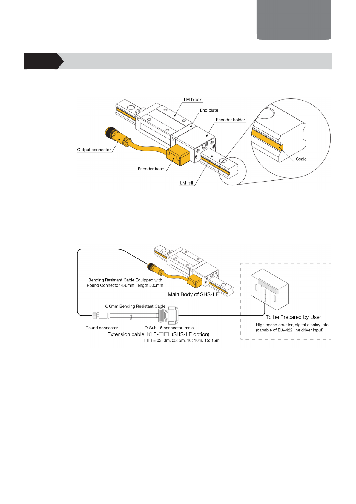
4-1 System configuration
This is a product that is capable of position measurement, linear guiding, and positioning with
the feedback loop control system in the LM rail directions.
Fig. 4-1 Names of individual parts
●The LM block is integrated with the encoder holder and encoder head.
●The encoder head reads the positions of N and S magnetic poles recorded in the scales
equipped on the sides of the LM rail. The interpolated NS magnetic pole pitch data is output
as the incremental A/B-phase differential outputs complied with EIA-422.
Fig. 4-2 Example of System Construction

4-2
4. About Product
4. About Product
4-2 Product Specifications
4-2-1 Dimensions/Lineup
●Block type: C/LC
Fig. 4-3 Block type C/LC
Model No.
Dimension [mm] Mass
M W L W1 W2 W3 L1 L2 K H3 E e0
LM Block
[kg]
LM Rail
[kg/m]
SHS20C/LC
30 63 115 (134)
20 21.5 72 59 (78) 46 25.4 4.6 12 4.3 0.61 (0.76) 2.3
SHS25C/LC
36 70 129 (146)
23 23.5 76.3 71 (88) 47.5 30.2 5.8 12 4.5 0.89 (1.06) 3.2
SHS30C/LC
42 90 143 (168)
28 31 88.3 80 (105) 50 35 7 12 5.8 1.56 (1.88) 4.5
SHS35C/LC
48 100 162 (192)
34 33 96 93 (123) 54.5 40.5 7.5 12 6.5 2.18 (2.82) 6.2
SHS45C/LC
60 120 180 (214)
45 37.5 111.3 106 (140) 57 51.1 8.9 16 8 3.64 (4.59) 10.4
●Block type: V/LV
Fig. 4-4 Block type V/LV
Model No.
Dimension [mm] Mass
M W L W1W2W3L1L2K H3E e0
LM Block
[kg]
LM Rail
[kg/m]
SHS20V/LV 30 44 115 (134)
20 12 62.5 59 (78) 46 25.4 4.6 12 4.3 0.5 (0.61) 2.3
SHS25V/LV 36 48 129 (146)
23 12.5 65.3 71 (88) 47.5 30.2 5.8 12 4.5 0.71 (0.84) 3.2
SHS30V/LV 42 60 143 (168)
28 16 73.3 80 (105) 50 35 7 12 5.8 1.16 (1.38) 4.5
SHS35V/LV 48 70 162 (192)
34 18 81 93 (123) 54.5 40.5 7.5 12 6.5 1.68 (2.12) 6.2
SHS45V/LV 60 86 180 (214)
45 20.5 94.3 106 (140) 57 51.1 8.9 16 8 2.94 (3.59) 10.4
*1 Values in brackets ( ) describe those for L Type
*2 The diameter of the attachment holes and attachment hole pitch on the rail should be the
same as those on SHS Type
Cable dimensions [mm]
Cable dimensions [mm]

4-3
4. About Product
4. About Product
●Block type: R/LR
Fig. 4-5 Block type R/LR
Model No.
Dimension [mm] Mass
M W L W1W2W3L1L2K H3E e0
LM Block
[kg]
LM Rail
[kg/m]
SHS25R/LR
40 48 129 (146)
23 12.5 65.3 71 (88) 47.5 34.2 5.8 12 4.5 0.83 (0.97) 3.2
SHS30R/LR
45 60 143 (168)
28 16 73.3 80 (105) 50 38 7 12 5.8 1.26 (1.58) 4.5
SHS35R/LR
55 70 162 (192)
34 18 81 93 (123) 54.5 47.5 7.5 12 6.5 2.08 (2.62) 6.2
SHS45R/LR
70 86 180 (214)
45 20.5 94.3 106 (140) 57 61.1 8.9 16 8 3.64 (4.59) 10.4
*1 Values in brackets ( ) describe those for L Type
*2 The diameter of the attachment holes and attachment hole pitch on the rail should be the
same as those on SHS Type
Cable dimensions [mm]
4-4
4. About Product
4. About Product
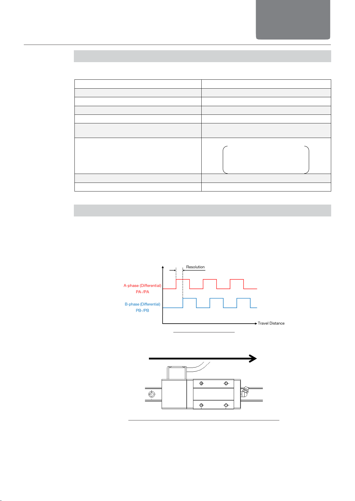
4-2-2 Encoder Specifications
●Linear Encoder Basic Specifications
Typ e Incremental magnetic encoder
Resolution [μm]* 1/5/10
Accuracy Repeatability in One Direction ± Resolution or less
Power supply [V] DC5V±5%
Max. Current Consumption [mA] 50 or less
Output
Incremental A-B phase differential output
EIA-422 line driver
Standard compliance
CE
EMC directive (2014/30/EU)
EN 61800.3:2004/AI!2012,
EN 550112009/AI:2010,
EN 610006-2:2005
Use and Storage Ambient Temperature 0 to 50°C (No freezing)
Use and Storage Ambient Humidity 20 to 80%RH (No condensation)
* It is the value after multiplying by 4.
4-2-3 Output Specifications
●The output signals from SHS-LE should be complied with EIA-422,
A/B-phased, differential outputs and in the line driver format.
●The higher-level device (e.g. counter) that you prepare yourself
should receive in the line receiver circuit.
Fig. 4-6 Output Signal
Fig. 4-7 Moving Direction and Output Signal Direction
When moving in cable direction: Lead by A-phase
(Encoder Positive Direction)

4-5
4. About Product
4. About Product
4-2-4 Extension cable
Fig. 4-8 Specifications of Extension Cable
●Make sure to connect the connector hood as it works as the frame grounding (FG).
●Consult with our IOT Innovation Division when an extension cable is to be made by yourself.
4-2-5 Max. Response Speed
Resolution [μm] 1 5 10
Maximum speed [m/s] 9.34 23.34 23.34
Shown above is the response speed of the encoder reading.
The maximum speed of the LM guide gives an impact to many conditions such as lubricant
condition and payload condition.
Consult with our IOT Innovation Division for details.
4-2-6 General Specifications
Temperature
Min. – Max.
In use 0 to 50°C
No freezing or
condensation
Storage 0 to 50°C
Humidity Use and Storage 20 to 80%
External Vibration / Impact
Encoder section : (BS EN 60068-2-6,7) (Vibration) frequency
55 to 2000Hz / max. acceleration 100m/s2
(Impact) Acceleration 500m/s2/ activating
time 6ms
LM Guide section : See the general catalog.
External Strong Electromagnetic Field Nonexistent
Extension cable: Bending Resistant ɸ6mm
□□=03: 3m, 05: 5m, 10: 10m, 15: 15m
L=□□m
◆Optional Extension Cable: KLE-□□

5. Mounting
5-1
5. Mounting
5. Mounting
See the Instruction Manual of the LM Guide [No. 1030-T34667] for mounting.

6-1
6. Permissible
Error
6. Permissible Error of the Mounting Surface
See the Instruction Manual of LM Guide [No. 1030-T34667] for permissible error of the
mounting surface.
7-1
7. Cables and
Wiring
7. Cables and Wiring
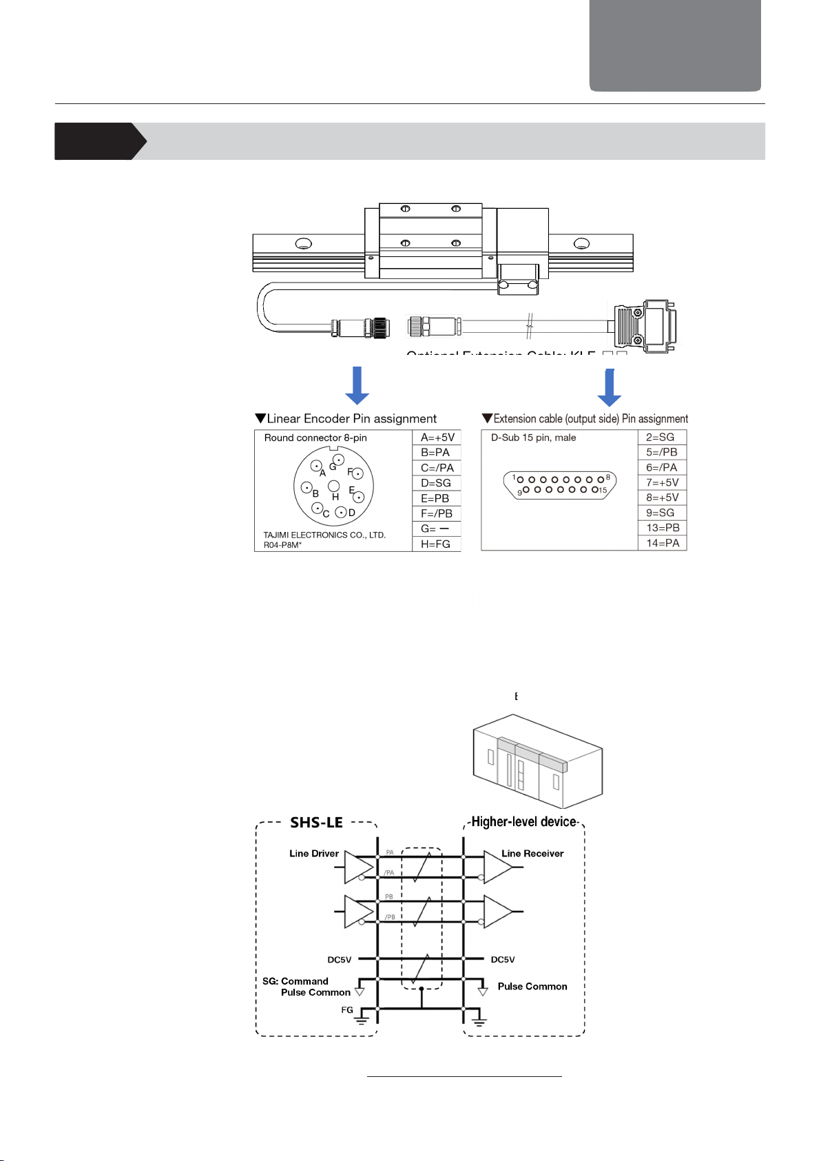
7-1 Wiring
Fig. 7-1 Wiring Specifications
* Because R04-P8M is a discontinued
product it will be replaced with its next
generation model ER04-P8M as the
stock ends.
There should be no change to
appearance dimensions, pin assignments
and communication configurations.
* Make sure to connect the
connector hood as it works as
the frame grounding (FG).
SHS-LE
Optional Extension Cable: KLE-□□
Example) Counter,
digital display,
motor driver etc.
To be Prepared by User
Higher-level device
7-2
7. Cables and
Wiring
7. Cables and Wiring
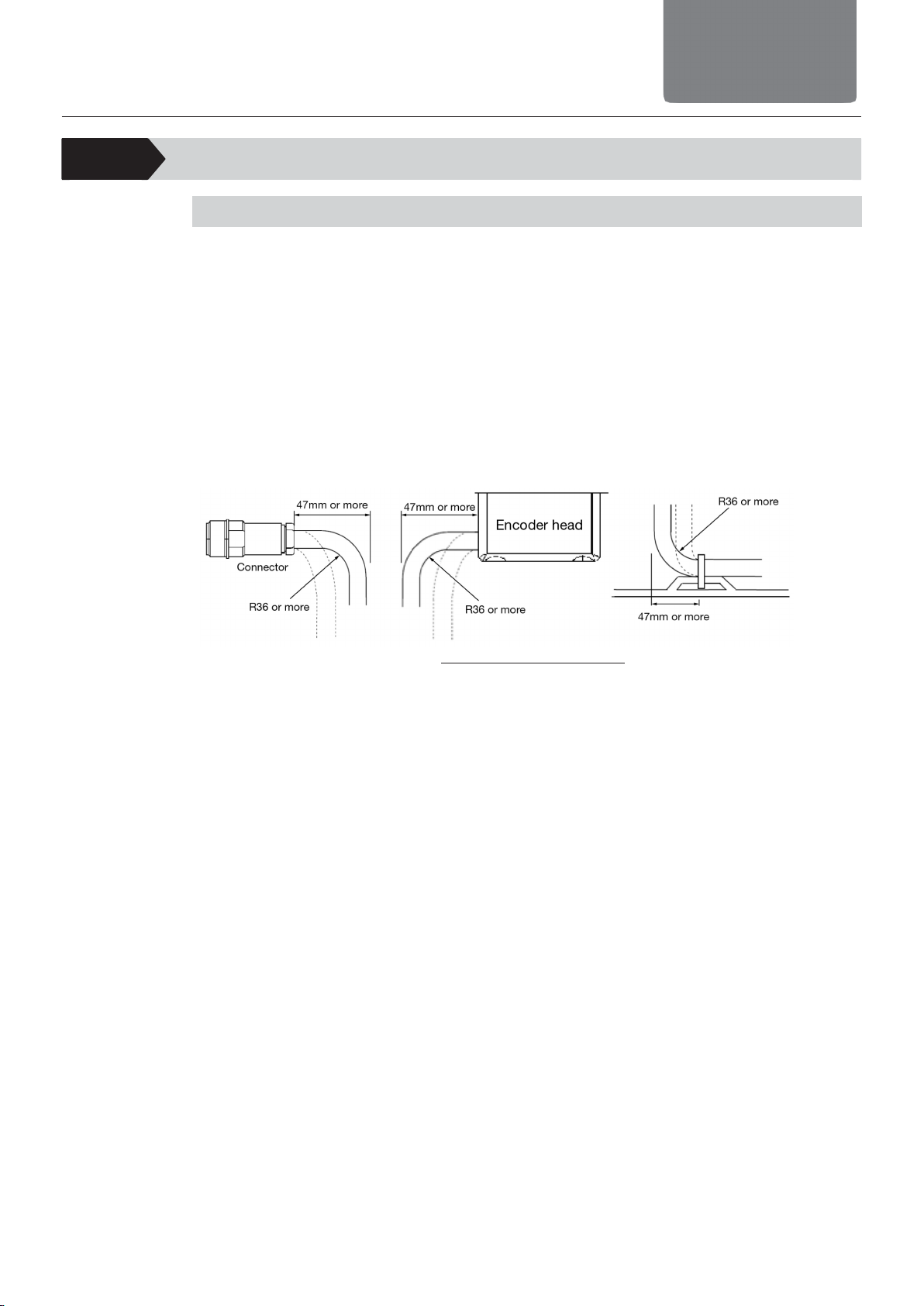
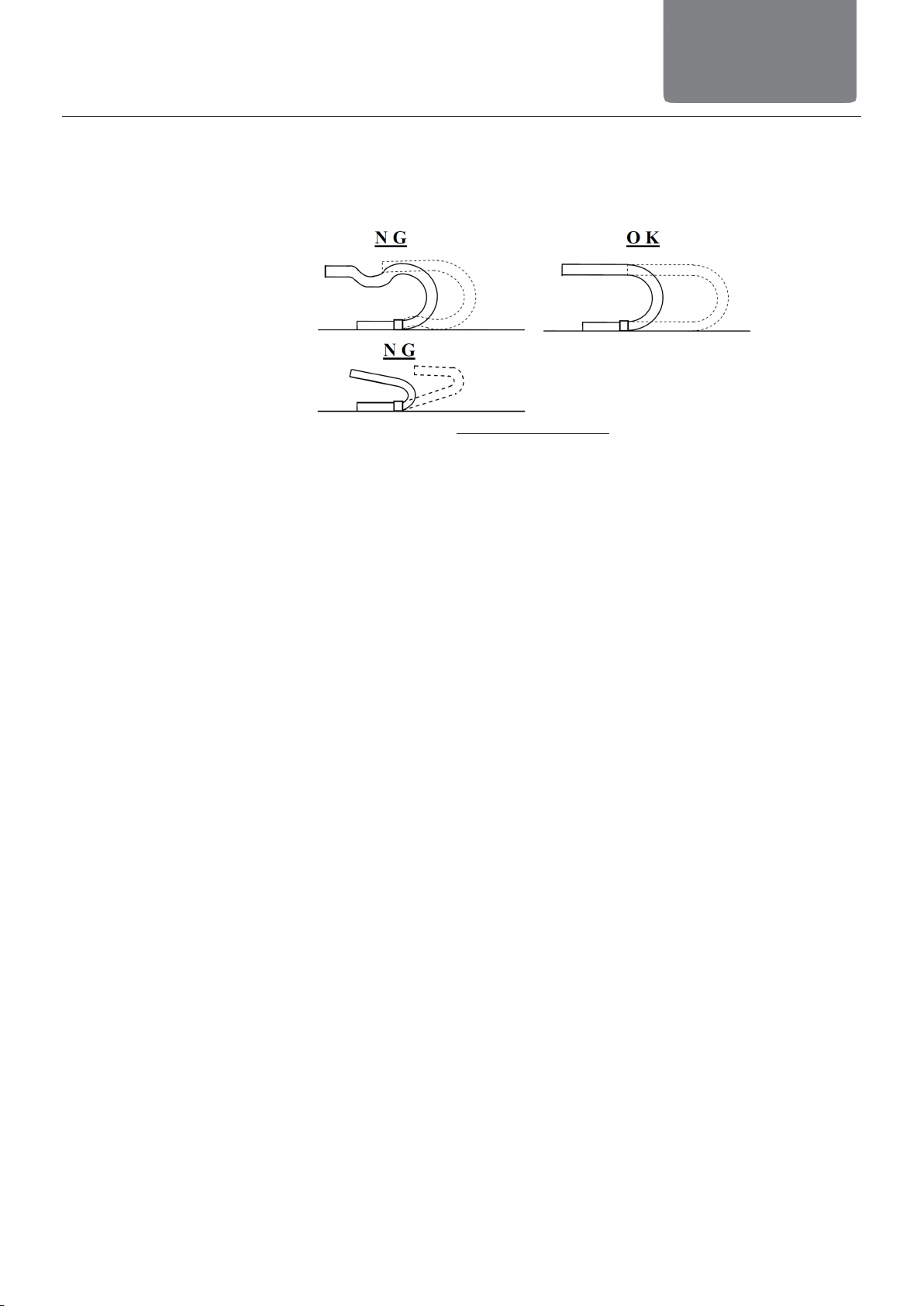
7-2 Minimum bending radius
Handling of Encoder Cable
The encoder cable is a bending resistant type with the minimum bending radius R36. Pay
attention to the following points when installing.
Note) If the installation is inappropriate, it may cause earlier line breakage.
●Cable Twist
Cables should be wired straightly without any twist.
Fixing or bending of cable while twisted may cause earlier line breakage.
●Fixation of Cable
Do not attempt to fix a cable where it moves.
Load will be concentrated at the fixed part, which may cause earlier line breakage. Fixing
points should be as minimum as possible.
Fig. 7-2 Fixation of Cable
Cable condition shown with dotted lines in the figure above could cause earlier line breakage
of a cable.
Consider wiring in the way that the solid lines show.
7-3
7. Cables and
Wiring
7. Cables and Wiring
●Cable length
Too long cable length could cause looseness while too short may cause tension at the fixing
point.
This may cause earlier line breakage. Adjust a cable to an optimum length when used.
Fig. 7-3 Cable length
●Cable Wiring
In order to avoid interface of cables as much as possible, keep a space for cables to be laid
in a row.

8-1
8. Lubrication
8. Lubrication
See the Instruction Manual of the LM Guide [No. 1030-T34667] for lubrication.

9-1
9. Troubleshooting
9. Troubleshooting
Symptom
Cause
Countermeasure
Related Page
Pulses cannot be
counted in higher-level
device
Power is not supplied
to the encoder head
Supply 5V DC power to the
linear encoder. Make sure
that there is no voltage drop
when the cable length is
extended.
4-2-2
Encoder Specifications
Interface is not
matched
Confirm that the interface to
receive signals is a line
receiver circuit complied
with EIA-422.
4-2-3
Output Specifications
Wrong Wiring Check the pin assignments
and lay them out correctly.
7-1 Wiring
Cable connector is
disconnected
Check if the connection at
connectors are performed
properly.
7-1 Wiring
Cable line breakage Check if there is any line
breakage on a cable.
Encoder head
malfunction
Consult with our IOT
Innovation Divisions if
replacement is necessary.
Scale malfunction Consult with our IOT
Innovation Divisions if
replacement is necessary.
Pulse count
significantly differ to
travel distance
Scale Error Check the entire stroke on
the scale surfaces with a
magnet viewer sold in
general. If there is an error in
arrangement of magnets, it
is necessary to have a
replacement.
Noise Check if there is any
influence of noise caused by
such as peripheral
servomotor, and take a
counteraction against noise
such as electrical isolation
and grounding if there is an
influence.
Gap error between
scale and encoder
head
Check if there is any
loosened or dropped screw
on the encoder head or
encoder holder.
Cable Error Check if there is any line
breakage on a cable.
Contact error on
cable connector
Check if joint on connectors
are connected properly.
Table of contents


