Thoebe Servo-Loop Preamplifier User manual

Your Thoebe Servo-Loop Preamplifier derives
its
"State of the Art"
performance from the technology and experience Great American
Sound Company engineers have gained from the development of
Thaedra. To insure equal performance, Thoebe uses
identical
active
circuitry (i.e. phono and line amp cards).
The result
is
a welcome addition to our growing line of Audiophile
equipment.
Itmust be remembered that Thoebe is acomplex, highly sophisticated
example of electronic equipment and some common sense must be
exercised when operating it.
1.
When Thoebe
is
turned on, there will be a time delay of several
seconds before anything will be heard. DO NOT attempt to turn up
gain during this period. When the relay closes, you may be delivering
in excess of
10V
RMS signal to amplifier, your reaction time
probably will not save your speakers (or ears) from permanent
damage.
2.
Turn level down between musical or source selections and when
turning the power on or off.
3.
Thoebe runs warm! Make sure ithas adequateventilation.
INTRODUCTION
WARNING:
To prevent fire or shock hazard, do not expose this
appliance to rain or moisture.

UNPACKING
Immediately upon receiving Thoebe, inspect the carton for evidence of
mishandling during shipment. Then, carefully unpack the amplifier
and inspect it for any sign of damage. Please save the shipping carton
and all the associated packing materials for future use. The shipping
materials have been carefully designed to transport your Thoebe with a
minimum of disturbance.
Shipment to the factory for any purpose
must
be made in the original
carton and packing. If the original carton
is
lost or damaged, contact
G.A.S. Company for replacement.
NOTE: If damage has occurred in shipping, please contact your dealer
immediately.
THOEBE is designed primarily for mounting on a shelf. An optional
wood cabinet
is
available.
Where THOEBE
is
to be inserted into
a
panel,
a
17
inch by
5-114
inch
cutout must be provided.
Allow enough space and/or holes for proper ventilation
-
Under no
cjrcumstances should the ventilation slots on the top and bottom of the
chassis be blocked.
RACK-MOUNTING: A rack mount panel version of THOEBE
is
available from your dealer, for use with the standard,
19
inch metal
rack. Be certain that the insulating plastic bushings (provided with the
panel) are used under each mounting screw to provide electrical
isolation of the unit from the metal rack.
CAUTION: Under no circumstances should you mount the unit in
a
vertical position. This will cause overheating of the unit.

With the power switch in the OFF position, plugthe line cord intoany
105-125V.50 or
60Hz
outlet. Do not turn on the power switch until all
other connectionshave been completed.
CONVENIENCE OUTLETS:
Refer
to
pictorial
A
Four convenience outlets have been provided on the rear panel to
power associated components in your system. Of these outlets, three
are controlled by the front panel onloff switch
(1000
Watts total) for
use with tape recorders, and medium powered amplifiers, (i.e. Son of
Ampzilla). The one remainingoutlet
is
unswitched and may be used for
turntables that have built-in power switches mechanically linked to
disengage their rubber idler wheels.
NOTE: We do not recommend using these outlets with high power
amplifiers. AMPZILLA cannot be plugged into these outlets.
Under no circumstances should
a
three-to-two prong adapter
be used to plug the AMPZILLA line cord into one of Thoebe's
convenience outlets! To keep within
its
warranty provisions,
AMPZILLA must be powered directly from
a
wall outlet where
the third wire can be grounded (No groundwire
is
requiredor
recommended for Thoebe).
PRE-PREAMP POWER SUPPLY
JACK
Located on the back panel of Thoebe
is
a power supply output
connector. This supplies
+
28V for usingGoliath pre-preamp.

CONNE
FSi&
MAlN OUTPUTS
Refer topictorial
A
Two stereo sets of audio output jacks are provided for connection to
power amplifiers or electronic crossovers. Special audio cables with
gold-plated contacts have been supplied for this purpose. The
gold-plated contacts have the low resistance necessary for a reliable
interconnection throughout the life of the equipment; additionally, the
high quality coaxial cable with braided shield guarantees highest
possible isolation from external electrostatic and electromagnetic
radiation.
The stereo output jacks are labeled MAlN 1 and
2.
They are both
identical and turn on is time-delayed by arelay.
Make certain that the cable contacts are fully engaged so that no loss of
circuit ground exists when the equipment is turned on. A very loud
hum or buzz will be heard if this condition does occur.
The source impedance of the two main outputs are each 60 Ohms, low
enough to permit the use of shielded, interconnecting cables up to 100
feet in length.
TAPE OUTPUTS
Refer topictorial
A
&
B
Two pairs of stereo output jacks are provided on the rear panel for
connection to any tape recorder having a minimum load impedanceof
5K
Ohms or higher. Since the source impedance of each
is
500
Ohms,
cables up to 100 feet may be used without high-frequency attenuation.
Unlike the main' outputs, the tape-output signals are independant of
balance, volume and tone control settings and are at a level equal to the
source-input level (Tuner, Aux, Etc.)
NOTE: The TAPE OUT stereo phone jack on the front panel has been
provided for tape-copying purposes and may always be utilized
in the same manner as the rear outputs. (Refer to the
paragraphon TAPE COPYING).
SOURCE CONNECTIONS
TUNER INPUT:
Refer topictorial
A
This
is
a high-level input with a rated sensitivity of 0.2 Volt. Although
labeled TUNER (AM or
FM),
this input may be used with any high
level source. The rated input impedance is
36K
Ohms with the volume
at maximum and increases to
53K
Ohms when the volume control
is
at
minimum. This condition exists only with the push-button source
selector inthe "TUNER" position, otherwise
it
is zero Ohms (Shorted).
NOTE: By design, THOEBE's high level inputcannot be overloaded by
any normal source.
AUXILIARY INPUTS:
Refer topictorial
A
The two stereo input pairs provided, labeled AUX 1 and AUX 2, are
identical in operation and sensitivity to the TUNER input described
above. They can be used with any auxiliary equipment havingadequate
outputs such as tape recorders, tuners, etc.
TAPE INPUTS:
Refer to pictorial
A
8
B
Two stereo pairs are provided, labeled TAPE 1 (Located on the rear
panel), and TAPE IN (Locatedon the front panel). These inputs, having
identical impedances and sensitivities as the TUNER input, are for
connection to tape recorder line outputs.
NOTE: TAPE 2 and Front Panel TAPE IN are connected in parallel
and are bothswitched by TAPE 2 switching.
PHONO INPUTS:
Refer to Pictorial
A
Two sets of phono inputs are provided; both are designed for use with
conventional magnetic phonographcartridges, see below.
MAGNETIC PHONO: All conventional magnetic cartridges (and
other types which require RlAA playback equalization but which do
5
not require input sensitivities below 1.6mV) may be used with this
input. The rated input impedance
is
47K
Ohms (100 pF shunt
capacitance) which is standard for magnetic phonograph cartridges.
Overload capability is
I
lOmV at
I
kHz which will accommodate
cartridgesconsideredtobe "High-output" types.
Well- shieldedcable is recommendedfor connecting tothe cartridge and
is usually supplied as part of the turntable or changer. Where longer
distances are desired for this connection,
it
is
not recommended the
phono cables exceed
5
feet, otherwise audible degradation of high
frequencies might be encountered. Special care must be taken than all
connections are tight and secure.
Ordinarily, an additional grounding wire
is
provided with the turntable
which should be connected to the grounding post located between the
phono inputs on the rear panel. Insome systems,
it
might be found that
this connection creates hum. Inthis case, noground connection should
be made. Be careful to keep all large transformers (such as found in
power amplifiers) away from the phono cartridge to prevent
magnetically-induced hum.
SPECIAL NOTES ON HUM REDUCTION
Unfortunately, by the very nature of the component, some components
are more prone to hum than others; no cable made is entirely immune
to radiated magnetic flux (hum). It follows then, that all cables inthe
system must be oriented for the lowest level of hurn.
The connecting cables from the turntable will pick up far more hum
than any other source. These cables must be oriented for maximum
hum cancellation. All wires carrying
AC
power should be located as far
away from the turntable and preamp input as is physically possible.
Under no circumstances should you ground the turntableor grounding
post to a water pipe or other such ground. Only through the power
amplifier should your system be grounded toearth.
Humcan also be introducedby a poor cable connector contact with the
outer grounding shell of the plug. Make sure that the outer shells on
RCA phono plugs are squeezed together enough to provide an
absoulutely solid ground connection. Try rotating the plugs to obtain
the best possibleground.

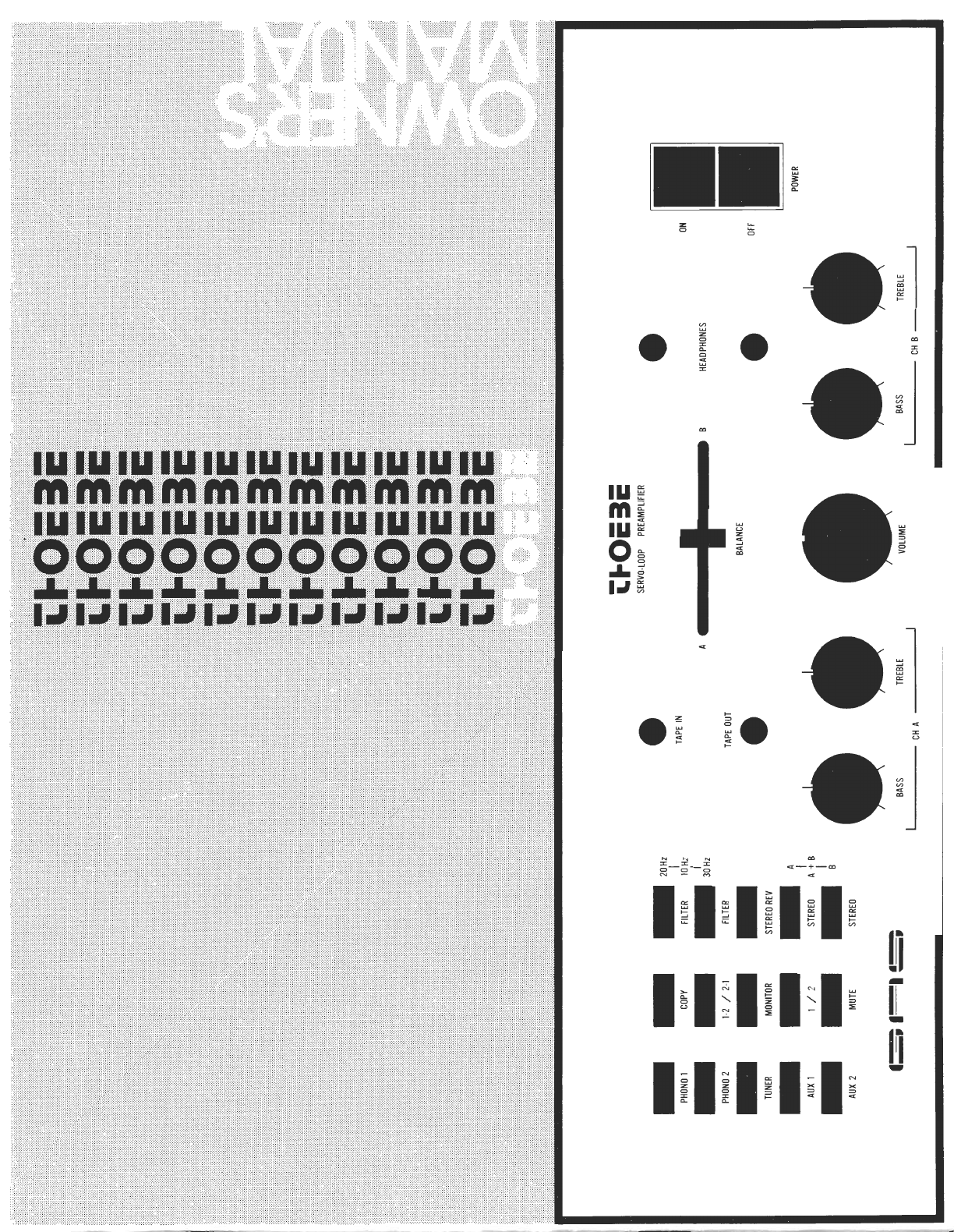
OPEMTION
Refer topictorial
B
When first operating THOEBE, set the controls as follows:
MODE:
TAPE MONITOR:
LOW FILTER
:
TAPE COPY:
BASS
&
TREBLE:
BALANCE:
LEVEL:
SELECTOR:
Stereo
Out
Off
Out
Flat (Mid position)
Mid position
Minimum (Counter-clockwise)
Desired source
Press the AC power switch; the pilot light will then be illuminated.
Increasethe level control tothe desired loudness. For detailed operation
of each control, read the following:
POWER SWITCH:
Refer topictorial
B
This push-push switch turns on THOEBE simultaneously with any
equipment that has been plugged into the rear panel switched
convenience outlets. A time-delay relay will cause a wait of
approximately
20
seconds before power is applied to the internal
circuits. This feature prevents turn-on voltage pulses from reaching
the power amplifier. Power turn-off
is
instantaneous when the off
button is pressed. Prior to turning THOEBE off,
it
is
advisable toturn
down the levelfrom very loudsettings.
LEVEL CONTROL:
Refer topictorial
B
This controls the output of both channels simultaneously. The stepped,
discrete-resistorconstruction maintains inter-channel balance within
0.5
dB
at
all settings.
It
has no effect on the signal at the TAPE OUTPUT
jacks.
BALANCE CONTROL:
Refer to pictorial
B
This controls the ratio betweenthe left and rightchannel.
It
is
useful in
achieving a balanced sound level where the speakers are at different
distances from the listener or thev are of dissimilar efficiencies. The
center of the control
is
detented.

BASS CONTROLS:
Refer to pictorial
B
These controls alter the low-frequency response of the two channels
below
600
Hz. The precise alterations can be seen in Figure 2. The
stepped, discrete-resistor construction insures channel-to-channel
accuracy within 1 dB throughout its range. When used in conjunction
with the low filter, a wide range of corrective alteration is possible,
partially negatingdeficiencies in speakers and source material.
TREBLE CONTROLS:
Refer topictorial
B
These controls alter the high frequency response of the two channels
above
1800
Hz. The precise alterations can be seen in Figure 2. They
have the same stepped, discrete-resistor construction as the BASS
controls. The boost positions incorporate supersonic filtering in a
Gaussian frequency distribution. The resultant curve causes minimum
phase distortion of high frequencies and provides the least
objectionable interference from noise.
LOW FILTER:
Refer to pictorial
B
Three low frequency attenuation turnover points are selectable with the
two push buttons marked "filter" on the front panel. Depressing the
top filter button initiates a 20 Hz rolloff. Depressing the lower button
initiates a 30 Hz rolloff. Depressing both buttons simultaneously
initiates
a
10 Hz rolloff. Attenuation slope
is
12dB per octave.
These filters will be useful when low frequency feed back or other
source of low frequency noise
is
encountered.
MODE
SELECTION:
Refer
to
pictorial
B
These buttons determine how the source inputs are channeled to the
output jacks. They function
as
follows:
A.
DEPRESSED The left channel is connected to both outputs.
B.
DEPRESSED The right channel is connected to both outputs.
A+B. Both buttons depressed. Both channels are combined and the
mixed (Mono) resultant
is
connected to both
outputs.
STEREO. Both buttons out. This, the normal position, connects
the left input to the leftoutput and the right input
tothe rightoutput.
REV Depressing this button connects the left input to
the opposite (right) output and the right input to
the opposite (left) output: simply reversing the
STEREO mode described above.
TAPE MONITOR:
Refer to pictorial
B
The normal position for this control
is
OUT. When OUT, the
signals selected by the source push buttons may be heard. When
you wish to monitor one of the tape recorders connected to the
tape inputs of THOEBE, simply depress the button labeled
"Monitor". To select the appropriate recorder, use the push button
just below the "monitor" button. OUT will monitor TAPE 1, IN
will monitor TAPE
2.
While in the TAPE 1, TAPE 2 position, the signal selected by
the push button source selector will be disconnected and the
signal from the selected tape recorder's output will be substituted.
The originally selected source signal will, however, continue
playing into the TAPE OUT jacks. Thus, by switching between
tape monitor and source position the two signals can be
compared while recording. Of course, this direct monitoring can
only be achieved with recorders having adequate head provisions
for this purpose.
TAPE COPY:
Refer topictorial
B
Two push buttons allow extremely versatile interconnections between
either of the two tape recordersconnected toTHOEBE.
Tape copy function
is
initiated by depressing "copy" button. "Copy"
select button directly below "copy" will function as follows:

1-2 Copy select TAPE 1 inputs are connected to TAPE
2
outputs.
button out.
.
.
(ie: The signals from tape recorder 1are fed out to
tape recorder 2).
2-1 Copy select
button in
.
.
.TAPE 2 inputs are connected to TAPE 1 outputs.
NOTE: It is impossible to record the signal from the push button
source selection onto the recorder corresponding to the second
digit of the COPY select position. For example, if the copy
switch is in position 1-2, the tape recorder connected to the
TAPE
2
jacks will only receive asignal from tape recorder 1. It
will not receive the signal selected by the source selector push
buttons (PHONO,TUNER, AUX, ETC.) To record the source
selected signals onto recorder 2, the TAPE COPY must be in
the off (out)position.
MUTE:
Refer topictorial
B
When "Mute" button is depressed, Thoebe's main output level is
attenuated 15 dB. This feature is useful when program must be
interrupted for any reason, and you wish to return to the exact level
before interruption.
HEADPHONES:
Refer topictorial
B
Either of the two HEADPHONE jacks accepts phones with impedances
of 100 Ohms or more. The upper jack leaves the power amplifier
connected, while the lower jack automatically disconnects the power
amplifier for headphones-onlylistening.
POWER SUPPLY JACK FOR
GOLIATH MOVING COIL PRE-PREAMP
1
1
DEMODULATORS
MAGNETIC
CARTRIDGE
CASSETTE
L,
DECK
'-1
.I
POWER
AMPLIFIER
TAPE
--l
DECK
I20
VAC
4
MAGNETIC
CARTRIDGE
u
TURNTABLE
NOTE:
MOST AUDIO CABLES ARE COLOR
CODED AND WHITE IS STANDARDIZED
FOR THE LEFT CHANNEL.
SPEAKER RIGHT
SPEAKER LEFT
I
-
LINE LINE
INPUT OUTPUT LINE LINE
INPUT OUTPUT
soap
TUNER
RED
BLK
Pictorial
A
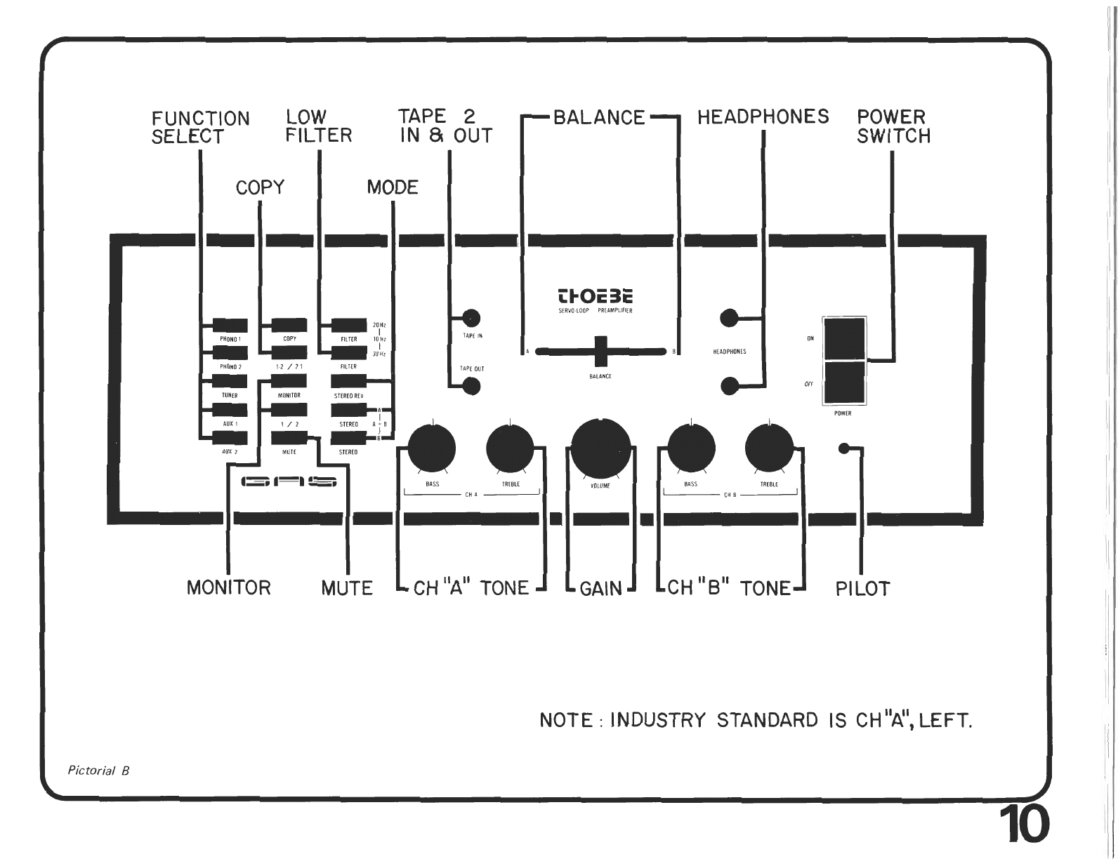
FUNCTION TAPE
2
SELECT FILTER IN
8r
OUT
MODE
*
TAP[ IN
TlPf
OUT
-
BALANCE
-
LkOE
3E
SERVO
LOOP
PRiPMPLlfI[R
HEADPHONES POWER
SWITCH
MONITOR MUTE
LCH"A"
TONEJ
LGAINJ
NOTE
:
INDUSTRY STANDARD IS
CHI'A';
LEFT.
Pictorial
B

PHONO
Gain
lnput impedance
lnput sensitivity
lnput overload
Equivalent input noise
Output impedance
HIGH
LEVEL
INPUTS:
Gain
lnput impedance
lnput sensitivity
lnput overload
Equivalent input noise
OUTPUTS:
MAlN output impedance
TAPE output impedance
Output load impedance
42dB
@
1000Hz
47KOhms (100pF shunt)
1.6 millivolts
@
1KHz
Approximately 110 millivolts
@
1KHz
Less than 0.6 microvolt 20-20KHz
Less than 0.25 microvolt 400-20KHz
Approximately 500 Ohms
20dB
@
1000Hz
Level control dependant
53K Ohms
@
full C.C.W.
36K Ohms
@
full C.W.
200 millivolts
@
1 KHz
1.2Volts RMS
Less than 5 microvolts 20-20KHz
60 Ohms Effective
Source impedance
Not less than 100 Ohms for MAlN
Not less than 10K Ohms for TAPE
ALL SPECIFICATIONS ARE DERIVED AT 2 VOLTS OUTPUT INTO A
600 OHM LOAD (Except TAPE which is driven into a 10K Ohm load)
Figure
1.
LOW-FILTER CHARACTERISTICS
.
dB
117,
Figure
2.
TONE CONTROL CHARACTERISTICS


From input to output, Thoebe
is
100%
full complementary,
a
concept
originally conceived by G.A.S. Company engineers. As versatile as the
unit
is,
there are only two stages of amplification. It
is
this simplicity
which allows totally open, unrestricted sound.
All direct
(D.C.)
coupled amplifiers suffer from
a
problem known as
d.c. drift. The conventional solution has been to use capacitor coupling
and/or large amounts of negative feedback, which introduce distortion
products of their own.
THE NO COMPROMISE SOLUTION: D.C. Servo Control
The concept of servo control has found many applications but has
never appeared in audio electronics. In Thoebe, servo amplifiers
(completely outside the audio path) sense and correct all d.c. voltages.
Both phonoand line amp circuits feature servo d.c. control.
Thoebe's line amp is actually asmall
Class
A power amplifier capable of
driving headphonesdirectly without the use of amplifier.

FIVE-YMR
WARMNN
THlS PRODUCT IS WARRANTEED UNDER THE FOLLOWING CONDITIONS:
PRODUCT IS PURCHASED THROUGH AN AUTHORIZED G.A.S. CO., INC. DEALER.
WARRANTY COVERS NORMAL OPERATING CONDITIONS OF HOME USE.
WARRANTY PERIOD BEGINS AS OF DATE OF SALE PROVIDED THlSCARD IS FILLEDOUT AND REGISTERED BY THE AUTHORIZED
G.A.S. DEALER WHERE THE PRODUCT WAS PURCHASED. REGISTRY PERIOD IS
20
DAYS.
DELIBERATE MISUSE, MISHANDLING, FAILURE TO REPORT RECEIVING DAMAGED MERCHANDISE, OR UNAUTHORIZEDTAMPER-
ING OR MODIFYINGTOTHIS MERCHANDISE AUTOMATICALLY VOIDS ALLWARRANTIES.
WARRANTY PERIOD FOR ALL G.A.S. CO., INC. FACTORY WIRED PRODUCTS IS
5
YEARS COVERING BOTH PARTS AND LABOR.
TRANSPORTATION CHARGESTO AND FROM THE DEALER OR FACTORY ARE EXCLUDED.
WARRANTY ON ALL G.A.S. CO., INC. PRODUCTS USED INANY OTHER FASHION OTHER THAN STATED ABOVE SHALL REDUCE THE
WARRANTY TIME PERIOD AND OTHER CONDITIONS TO NEGOTIATIONS BETWEEN G.A.S. CO.. INC. AND PROSPECTIVE USER.
THIS WARRANTY SHALL EXTEND TO EACH SUCCESSIVE OWNER PROVIDED G.A.S. CO., INC. IS NOTIFIED BY REGISTERED MAIL
WITHIN
20
DAYS OF RESALE BY INITIAL OR PRESENT OWNER. THlS NOTIFICATION SHALLCONSIST OF DATE OF SALE, AMOUNT.
NAME AND ADDRESS OF NEW OWNER.
G.A.S. CO., INC. GUARANTEES THAT ALL G.A.S. CO., INC. PRODUCTS ARE FREE FROM DEFECTS INMATERIALS AND/OR WORK-
MANSHIP FOR THE REQUIRED WARRANTY PERIOD. OWNERS OF G.A.S. CO., INC. PRODUCTS ARE ENTITLEDTO FREE PERIODIC
CHECKS, AT EITHER DEALER OR FACTORY LOCATIONS. TO INSURE PRODUCT PERFORMANCE TOORlGlNALSPECIFICATIONS.
G.A.S. CO., INC. WILL REPAIR OR REPLACE ANY AND ALL DEFECTIVE PARTS ATNOCHARGE, PROVIDEDALLOTHER CONDITIONS
OF THE WARRANTY ARE INORDER. THlS FREE CHECKOUT SERVICE IS LIMITEDTO A MAXIMUMOF ONCE A YEAR, PER UNIT, PER
CUSTOMER.
THlS WARRANTY IS NOT VALID UNLESSACCOMPANIED BY SALES SLIP VALIDATION OR PROPERLY STATED INVOICE (COPY).

880005-876
Printed
in
U.S.A.
THE GREAT AMERICAN SOUND
CO..
INC.
20940
LASSEN STREET CHATSWORTH, CALIFORNIA
9131
1
(213)
998-8100
Table of contents


