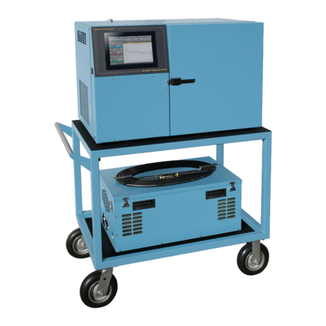
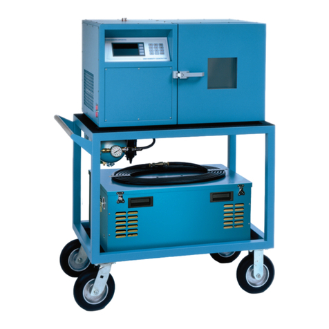
Thunder Scientific 9500 User manual

Thunder Scientific Corporation
Model 9500 System Manual

MODEL 9500
AUTOMATED TWO-PRESSURE
HUMIDITY GENERATOR
OPERATION AND
MAINTENANCE MANUAL
Copyright © 2022
THUNDER SCIENTIFIC CORPORATION
623 WYOMING BLVD. SE
ALBUQUERQUE, NEW MEXICO 87123-3198
USA
www.thunderscientific.com
Tel: 1.505.265.8701 FAX: 1.505.266.6203
e-mail: [email protected]
Document Edition 3.0 July 2022
THUNDER SCIENTIFIC® is the registered trademark of Thunder Scientific Corporation.
All the information provided in this document is correct and true at the time of publication.
Thunder Scientific Corporation reserves the right to change any technical data without notice.

PN 2566073, 1/2006
Tämä tuote noudattaa WEEE-direktiivin (2002/96/EY)
merkintävaatimuksia. Kiinnitetty etiketti osoittaa, että tätä
sähkö-/elektroniikkalaitetta ei saa hävittää kotitalousjätteissä.
Tuoteluokka: Viitaten WEEE-direktiivin liitteessä I mainittuihin
laitteisiin, tämä tuote on luokiteltu luokan 9 “Tarkkailu- ja
ohjauslaitteet” -tuotteeksi.
Ei saa heittää kotitalousjätteiden mukana!
Palauta tarpeettomat tuotteet ottamalla yhteyttä valmistajan
websivustoon, joka mainitaan tuotteessa tai paikalliseen
myyntitoimistoon tai jakelijaan.
Suomi
Dette produkt er i overensstemmelse med kravene om afmærkning
i WEEE-direktivet (2002/96/EC). Det påhæftede mærkat angiver,
at du ikke må bortskaffe dette elektriske/elektroniske produkt via
husholdningsaffald.
Produktkategori: Med reference til kravene i WEEE-direktivets
bilag I klassificeres dette produkt som et produkt til “overvågning
og kontrolinstrumentering” i kategori 9.
MÂ ikke bortskaffes via husholdningsaffald!
Hvis du vil returnere uønskede produkter, skal du besøge
producentens websted, som vises på produktet, eller den lokale
forhandler eller distributør.
Dansk
This product complies with the WEEE Directive (2002/96/EC) marking
requirements. The affixed label indicates that you must not discard
this electrical/electronic product in domestic household waste.
Product Category: With reference to the equipment types in the
WEEE Directive Annex I, this product is classed as category 9
“Monitoring and Control Instrumentation” product.
Do not dispose in domestic household waste!
To return unwanted products, contact the manufacturer’s web site
shown on the product or your local sales office or distributor.
English
Ce produit est conforme aux normes de marquage de la directive
DEEE (2002/96/CE). La présence de cette étiquette indique que
cet appareil électrique/électronique ne doit pas être mis au rebut
avec les déchets ménagers.
Catégorie de EEE : Cet appareil est classé comme catégorie 9 parmi
les « instruments de surveillance et de contrôle » en référence aux
types d’équipements mentionnés dans l’Annexe I de la directive DEEE.
Ne pas éliminer avec les autres déchets ménagers !
Pour renvoyer les produits indésirables, contacter le site Web du
fabricant mentionné sur le produit, ou son distributeur ou bureau de
ventes local.
Français
Este producto cumple la Directiva WEEE (2002/96/EC) sobre
requisitos de las marcas. La etiqueta que lleva pegada indica
que no debe desechar este producto eléctrico o electrónico con
los residuos domésticos.
Categoría del producto: con referencia a los tipos de equipo
del anexo I de la Directiva WEEE, este producto está clasificado
como categoría 9 de “Instrumentación de supervisión y control”.
¡No lo deseche con los residuos domésticos!
Para devolver productos que no desee, póngase en contacto con
el sitio Web del fabricante mostrado en el producto, o con la oficina
de ventas o distribuidor local.
Español

Dieses Produkt stimmt mit den Kennzeichnungsanforderungen
der WEEE-Richtlinie (2002/96/EC) überein. Das angebrachte
Etikett weist darauf hin, dass dieses elektrische/elektronische
Produkt nicht in Hausmüll entsorgt werden darf.
Produktkategorie: In Bezug auf die Gerätetypen in Anhang
I der WEEE-Richtlinie ist dieses Produkt als Kategorie 9
“Überwachungs- und Kontrollinstrument” klassifiziert.
Nicht in Hausmüll entsorgen!
Zur Rückgabe von unerwünschten Produkten die auf dem
Produkt angegebene Website des Herstellers oder die zuständige
Verkaufsstelle bzw. den zuständigen Fachhändler konsultieren.
Deutsch
Questo prodotto risponde ai requisiti sull’etichettatura stabiliti
nella Direttiva RAEE (2002/96/CE). Il simbolo apposto indica che
non si deve gettare questo prodotto elettrico o elettronico in un
contenitore per rifiuti domestici.
Categoria del prodotto: con riferimento ai tipi di apparecchiature
elencate nell’Allegato 1 della Direttiva RAEE, questo prodotto
rientra nella categoria 9 “Strumenti di monitoraggio e di controllo”.
Non gettare in un contenitore per rifiuti domestici.
Per restituire prodotti non desiderati, visitare il sito Web del
produttore riportato sul prodotto o rivolgersi al distributore o
all’ufficio vendite locale.
Italiano
Este produto está em conformidade com as exigências de rotulagem
da Directiva WEEE (2002/96/EC). O rótulo afixado indica que o
utilizador não deve deitar este produto eléctrico/electrónico fora
juntamente com o lixo doméstico.
Categoria do produto: No que se refere aos tipos de equipamento lis-
tados no Anexo I da Directiva WEEE, este produto está classificado como
produto da categoria 9, “Instrumentação de monitorização e controlo”.
Não deite fora juntamente com o lixo doméstico!
Para devolver produtos indesejados, contacte o fabricante através do
Website constante do produto ou contacte o seu representante de
vendas ou distribuidor local.
Português
Dit product voldoet aan de merktekenvereisten van de AEEA-
richtlijn (2002/96/EG). Het aangebrachte merkteken duidt erop dat
dit elektrische/elektronische product niet met het huishoudelijk
afval mag worden afgevoerd.
Productcategorie: Met betrekking tot de apparatuurcategorieën
van bijlage I van de AEEA-richtlijn, valt dit product onder categorie
9 ‘meet- en controle-instrumenten’.
Niet afvoeren met huishoudelijk afval!
Om ongewenste producten te retourneren, neemt u contact op
met de website van de fabrikant die op het product staat vermeld,
of met uw plaatselijke verkoopkantoor of distributeur.
Nederlands
Denna produkt uppfyller märkningskraven enligt WEEE Directive
(2002/96/EC). Märkningsetiketten anger att du inte får kassera denna
elektriska/elektroniska produkt tillsammans med vanliga hushållssopor.
Produktkategori: Med hänvisning till utrustningstyperna i
WEEE Directive Annex I, är denna produkt klassad som kategori 9
“Monitoring and Control Instrumentation” (Instrument för
övervakning och styrning).
Får ej kasseras tillsammans med vanliga hushållssopor!
Returnera ej önskvärda produkter genom att gå till tillverkarens
webbplats, vilken anges på produkten, eller till det lokala
försäljningskontoret eller distributören.
Svenska
Dette produktet oppfyller bestemmelsene ifølge WEEE-direktiv
(2002/96/EC) med krav til merking. Påsatt merke viser at det ikke
er tillatt å kassere dette elektriske/elektroniske produktet sammen
med husholdningsavfall.
Produktkategori: På grunnlag av utstyrstypene i WEEE-
direktivet, vedlegg I, er dette produktet klassifisert i kategori 9,
“Instrumentering for overvåking og kontroll”.
Må ikke kastes sammen med husholdningsavfall!
Ved behov for returforsendelse av uønskede produkter må du gå
til produsentens nettside som er angitt på produktet, eller du må
kontakte det lokale salgskontoret eller den lokale forhandleren.
Norsk

1
Model 9500 System Manual – Document #OM9500 - Edition 3.0 July 2022
1TABLE OF CONTENTS
2Getting Started 7
2.1 About ....................................................................................................................................................... 7
2.2 Notice.......................................................................................................................................................8
2.3 Safety Information ...................................................................................................................................8
2.3.1 Live Power Source ......................................................................................................................8
2.3.2 Electrostatic Discharge ................................................................................................................8
2.3.3 Compressed Gas .......................................................................................................................... 8
2.3.4 Personal Protective Equipment.................................................................................................... 8
2.3.5 Safety Symbols............................................................................................................................ 8
2.4 Technical Support .................................................................................................................................... 9
2.5 License Agreement .................................................................................................................................. 9
2.6 Warranty ................................................................................................................................................ 11
2.7 Copyright ...............................................................................................................................................11
2.8 Trademarks ............................................................................................................................................ 11
2.9 Specifications......................................................................................................................................... 12
2.10 Uncertainty ........................................................................................................................................... 13
2.11 Facility Requirements ............................................................................................................................ 14
2.11.1 Environment ..............................................................................................................................14
2.11.2 Floor Space................................................................................................................................14
2.11.3 Power......................................................................................................................................... 14
2.11.4 Air Supply ................................................................................................................................. 14
2.11.5 Cooling Water Supply ............................................................................................................... 15
2.11.6 Distilled Water Supply .............................................................................................................. 15
2.11.7 Wastewater Drain ......................................................................................................................15
2.11.8 Propylene Glycol ....................................................................................................................... 15
2.12 Installation.............................................................................................................................................. 16
2.12.1 Uncrating ...................................................................................................................................16
2.12.2 Positioning................................................................................................................................. 16
2.12.3 Touch Panel PC (HMI).............................................................................................................. 16
2.12.4 Facility Connections.................................................................................................................. 17
2.12.5 Temperature Bath Filling Procedure ......................................................................................... 19
2.12.6 Temperature Bath Draining Procedure......................................................................................20
2.12.7 Holding Tank Initial Filling Procedure...................................................................................... 21
2.12.8 Holding Tank Draining Procedure.............................................................................................21
2.12.9 Reservoir Initial Filling Procedure ............................................................................................ 21
2.12.10 Setting Supply Pressure Regulator ............................................................................................ 22
2.13 Quick Start ............................................................................................................................................. 25
2.13.1 Power-Up................................................................................................................................... 25
2.13.2 Loading Screen..........................................................................................................................25
2.13.3 ControLog Screen...................................................................................................................... 26
2.13.4 Control Parameters .................................................................................................................... 27
2.13.5 Control Modes........................................................................................................................... 29
2.13.6 Generating and Shutting down ..................................................................................................30
2.13.7 Power-Off.................................................................................................................................. 31
2.13.8 Set Date and Time ..................................................................................................................... 32
2.13.9 Help ...........................................................................................................................................33
3Principle of Operation 34

2
Model 9500 System Manual – Document #OM9500 - Edition 3.0 July 2022
3.1 Pre-Saturation (TPsat) .............................................................................................................................. 34
3.2Expansion Valve (TExV) ......................................................................................................................... 34
3.3 Saturation Temperature (TS) .................................................................................................................. 35
3.4 Chamber Temperature (TC).................................................................................................................... 35
3.5 Saturation Pressure (PS) .........................................................................................................................35
3.6 Chamber Pressure (PC)........................................................................................................................... 35
3.7 Humidity Formulas ................................................................................................................................ 35
4ControLog Interface 36
4.1 Menu Bar ............................................................................................................................................... 37
4.1.1 File Menu Tab ........................................................................................................................... 37
4.1.2 Home Menu Tab........................................................................................................................ 43
4.1.3 Units Menu Tab......................................................................................................................... 46
4.1.4 Operation Menu Tab.................................................................................................................. 48
4.1.5 Profile Menu Tab....................................................................................................................... 51
4.1.6 Utilities Menu Tab..................................................................................................................... 53
4.1.7Graph Menu Tab........................................................................................................................ 59
4.1.8 Data Menu Tab.......................................................................................................................... 62
4.1.9 Device Settings Menu Tab ........................................................................................................ 65
4.1.10 Help ...........................................................................................................................................67
4.2 Parameters Tab Group ........................................................................................................................... 68
4.2.1 Tiles ...........................................................................................................................................71
4.2.2 9500 Parameter Tab................................................................................................................... 75
4.2.3 Device Parameter Tabs.............................................................................................................. 81
4.3 Data and Graph Tab Group .................................................................................................................... 82
4.3.1 Data Tabs................................................................................................................................... 83
4.3.2 Graph Tabs ................................................................................................................................ 83
4.3.3 Profile Tab ................................................................................................................................. 83
4.4 Information Tab Group .......................................................................................................................... 84
4.4.1 Status Log.................................................................................................................................. 86
4.4.2 9500 Reported Warnings and Errors .........................................................................................86
4.4.3 System timing............................................................................................................................ 86
4.4.4 9500 Interface Console.............................................................................................................. 87
4.4.5 Device Interface Console........................................................................................................... 87
4.5 Status Bar ...............................................................................................................................................88
4.5.1 Connection and Run Status........................................................................................................ 88
4.5.2 Auto Profile Controls and Status ...............................................................................................89
4.5.3 Current Point Time .................................................................................................................... 90
4.5.4 Set Date and Time ..................................................................................................................... 90
5Fluid Levels and Bath Control 92
5.1 Water Reservoir Level ........................................................................................................................... 92
5.1.1 Fill Water Reservoir .................................................................................................................. 93
5.2 Bath Reserve Level ................................................................................................................................ 95
5.3 Holding Tank Level ...............................................................................................................................96
5.3.1 Fill Holding Tank ...................................................................................................................... 96
5.4 Bath Level.............................................................................................................................................. 99
5.4.1 Raising the Bath ........................................................................................................................ 99
5.4.2 Lowering the Bath ................................................................................................................... 100
5.5 Pump Rotation Test.............................................................................................................................. 101
5.6 Liquid Level Sensors ........................................................................................................................... 102
5.6.1 Pre-Saturator Level.................................................................................................................. 102
5.6.2 Upper Bath Level .................................................................................................................... 102
5.6.3 Lower Bath Level .................................................................................................................... 103

3
Model 9500 System Manual – Document #OM9500 - Edition 3.0 July 2022
5.6.4 Pump Flow Switch .................................................................................................................. 103
6Calibration 104
6.1 Temperature Calibration ...................................................................................................................... 104
6.1.1 Equipment Required................................................................................................................ 105
6.1.2 Calibration Procedure.............................................................................................................. 105
6.2 Pressure Transducer Calibration .......................................................................................................... 127
6.2.1 Equipment Required................................................................................................................ 127
6.2.2 External Calibration Procedure ............................................................................................... 127
6.2.3 Internal Calibration Procedure................................................................................................. 129
6.2.4 Supply Pressure ....................................................................................................................... 148
6.3 Mass Flow Meter Calibration............................................................................................................... 149
6.3.1 Equipment Required................................................................................................................ 149
6.3.2 Calibration Procedure.............................................................................................................. 149
6.4 Viewing and Editing Calibration Coefficients ..................................................................................... 166
6.4.1 Coefficient Calculator ............................................................................................................. 168
7Graphing 173
7.1 Creating a New Graph.......................................................................................................................... 174
7.1.1 Line Properties......................................................................................................................... 176
7.1.2 Chart Properties ....................................................................................................................... 177
7.2 Customizing a Graph ........................................................................................................................... 178
7.2.1Pan........................................................................................................................................... 178
7.2.2 Zoom ....................................................................................................................................... 179
7.2.3 Zoom Graph’s X-Axis............................................................................................................. 180
7.2.4 Zoom Graph’s Y-Axis............................................................................................................. 181
7.2.5 Auto Scale ............................................................................................................................... 181
7.2.6 Scale ........................................................................................................................................ 181
7.2.7 Scale X-Axis............................................................................................................................ 181
7.2.8 Scale Y-Axis............................................................................................................................ 181
7.2.9 Graph Properties...................................................................................................................... 182
7.3 Saving a Graph..................................................................................................................................... 185
8Data and Data Summary 187
8.1 Device Data Tabs ................................................................................................................................. 191
8.2 File Data Tabs ...................................................................................................................................... 192
8.3 Data Summary Tabs............................................................................................................................. 195
8.3.1 Creating a Data Summary........................................................................................................ 196
8.4 Recorded Data Points Tab.................................................................................................................... 203
8.4.1 How to Record a Data Point .................................................................................................... 204
9Auto Profiling 209
9.1 Creating a New Profile......................................................................................................................... 211
9.2 Saving a Profile.................................................................................................................................... 221
9.3 Opening a Profile ................................................................................................................................. 223
9.4 Running an Auto Profile ...................................................................................................................... 225
9.4.1 Understanding Profile Phases.................................................................................................. 227
9.4.2 Manual Override of Profile...................................................................................................... 230
10 Connections 233
10.1 Serial Connection................................................................................................................................. 234
10.1.1 Serial Connection Example 1 .................................................................................................. 249

4
Model 9500 System Manual – Document #OM9500 - Edition 3.0 July 2022
10.1.2 Serial Connection Example 2 .................................................................................................. 261
10.2 Analog Connection .............................................................................................................................. 278
10.2.1 Analog Connection Example................................................................................................... 288
10.3 Manual Connection.............................................................................................................................. 297
10.3.1 Manual Connection Example .................................................................................................. 301
10.4 Opening a Device Connection ............................................................................................................. 310
11 Data Backup 311
12 System 312
12.1 Control System..................................................................................................................................... 312
12.1.1 Control Computer.................................................................................................................... 312
12.1.2 HMI Computer ........................................................................................................................ 312
12.1.3 ControLog® Software ............................................................................................................. 313
12.1.4 HumiCalc with Uncertainty® Software .................................................................................. 314
12.2 Electrical System ................................................................................................................................. 315
12.2.1 Solid State Relays.................................................................................................................... 315
12.3 Pneumatic System ................................................................................................................................ 317
12.3.1 Pressure Measurement............................................................................................................. 318
12.3.2 Mass Flow Rate Measurement ................................................................................................ 319
12.3.3 Pre-Saturator............................................................................................................................ 319
12.3.4 Reservoir ................................................................................................................................. 320
12.3.5 Saturators................................................................................................................................. 321
12.3.6 Flow Control Valve ................................................................................................................. 321
12.3.7 Expansion Valve...................................................................................................................... 321
12.3.8 Chamber Pressure Control Valve ............................................................................................ 322
12.3.9 Test Chamber........................................................................................................................... 322
12.3.10 Condensate Pump .................................................................................................................... 322
12.4 Fluid System ........................................................................................................................................ 323
12.4.1 Liquid Level Measurement...................................................................................................... 323
12.4.2 Fluid Flow Measurement......................................................................................................... 324
12.4.3 Temperature Controlled Bath .................................................................................................. 324
12.4.4 Bath Heating............................................................................................................................ 324
12.4.5 Bath Refrigeration ................................................................................................................... 324
12.4.6 Temperature Measurement ...................................................................................................... 325
13 Maintenance 326
13.1 Bath Fluid............................................................................................................................................. 326
13.2 Air Input Filter ..................................................................................................................................... 326
13.3 Pressure Regulator ............................................................................................................................... 327
13.4 Pre-Saturator Liquid Level Checkout .................................................................................................. 327
13.5 Reservoir Liquid Level Alignment ...................................................................................................... 327
13.6 Holding Tank Liquid Level Adjustment .............................................................................................. 329
13.7 Bath Liquid Level Checkout ................................................................................................................ 330
13.8 Warning and Error Messages............................................................................................................... 330
13.8.1 Bath Temperature at Minimum Limit...................................................................................... 330
13.8.2 Bath Temperature Over Range or at Maximum Limit............................................................. 331
13.8.3 Chamber Temperature at Minimum Limit............................................................................... 331
13.8.4 Chamber Temperature Over Range or at Maximum Limit...................................................... 331
13.8.5 Saturation Temperature at Minimum Limit............................................................................. 331
13.8.6 Saturation Temperature Over Range or at Maximum Limit.................................................... 331
13.8.7 Pre-Saturation Temperature at Minimum Limit ...................................................................... 331
13.8.8 Pre-Saturation Temperature Over Range or at Maximum Limit ............................................. 331
13.8.9 Expansion Valve Temperature at Minimum Limit.................................................................. 331

5
Model 9500 System Manual – Document #OM9500 - Edition 3.0 July 2022
13.8.10 Expansion Valve Temperature Over Range or at Maximum Limit......................................... 331
13.8.11 Insufficient Supply Pressure to Generate................................................................................. 332
13.8.12 Supply Pressure Over Range or at Maximum Limit................................................................ 332
13.8.13 High-Range Pressure at Minimum Limit................................................................................. 332
13.8.14 High-Range Pressure Over Range or at Maximum Limit ....................................................... 332
13.8.15 Low-Range Pressure at Minimum Limit ................................................................................. 332
13.8.16 Low-Range Pressure Over Range or at Maximum Limit ........................................................ 332
13.8.17 Chamber Pressure at Minimum Limit ..................................................................................... 332
13.8.18 Chamber Pressure Over Range or at Maximum Limit ............................................................ 332
13.8.19 Mass Flow Rate at Minimum Limit......................................................................................... 332
13.8.20 Mass Flow Rate Over Range or at Maximum Limit................................................................ 333
13.8.21 Flow Valve Reported Error: .................................................................................................... 333
13.8.22 Flow Valve Failed to Find Home Position .............................................................................. 333
13.8.23 Flow Valve at Minimum Limit................................................................................................ 333
13.8.24 Flow Valve at Maximum Limit ............................................................................................... 333
13.8.25 Expansion Valve Reported Error:............................................................................................ 333
13.8.26 Expansion Valve Failed to Find Home Position...................................................................... 333
13.8.27 Expansion Valve at Minimum Limit – Check for air leaks ..................................................... 333
13.8.28 Expansion Valve at Maximum Limit – Reduce Mass Flow Rate............................................ 333
13.8.29 Chamber Valve Reported Error:.............................................................................................. 333
13.8.30 Chamber Valve Failed to Find Home Position ........................................................................ 334
13.8.31 Chamber Valve at Maximum Limit – Check chamber for air leaks ........................................ 334
13.8.32 Low-Range Pressure Transducer Not Responding.................................................................. 334
13.8.33 High-Range Pressure Transducer Not Responding ................................................................. 334
13.8.34 Chamber Pressure Transducer Not Responding ...................................................................... 334
13.8.35 Check and Clean Bath Level Probes ....................................................................................... 334
13.8.36 No Fluid Flow – Check Fluid Circulation System................................................................... 334
13.8.37 No Bath Fluid Heat.................................................................................................................. 334
13.8.38 No Pre-Saturator Heat ............................................................................................................. 334
13.8.39 No Expansion Valve Heat ....................................................................................................... 335
13.8.40 Cabinet Temperature Over Range or at Minimum/Maximum Limit – Check Cabinet Fans... 335
13.8.41 Unable to Fill Pre-Saturator..................................................................................................... 335
13.8.42 Unable to Fill Bath Fluid Holding Tank.................................................................................. 335
13.8.43 Unable to Fill distilled Water Reservoir .................................................................................. 335
13.8.44 Distilled Water Reservoir is Empty......................................................................................... 335
13.8.45 Distilled Water Reservoir is Low ............................................................................................ 335
13.8.46 Bath Fluid Holding Tank is Empty.......................................................................................... 335
13.8.47 Refrigeration Compressor Low Side Pressure at Minimum Limit .......................................... 336
13.8.48 Refrigeration Compressor Low Side Pressure Over Range or at Maximum Limit ................. 336
13.8.49 Refrigeration Compressor High Side Pressure at Minimum Limit.......................................... 336
13.8.50 Refrigeration Compressor High Side Pressure Over Range or at Maximum Limit................. 336
13.8.51 System Failed to Vent Pressure on Shutdown......................................................................... 336
13.8.52 Pressure Alignment Error - Check Low and High-Range Pressure Transducers. ................... 336
13.8.53 Mass Flow Rate is being limited to achieve Humidity setpoint. ............................................. 336
13.8.54 Insufficient Supply Pressure to reach setpoint......................................................................... 337
13.8.55 Switching Supply Pressure Inputs - Mass Flow Rate reduced................................................. 337
14 RS-232 commands 337
14.1 Serial Settings ...................................................................................................................................... 337
14.2 Get and Set Commands........................................................................................................................ 337
14.2.1 %RH ........................................................................................................................................ 337
14.2.2 Frost Point ............................................................................................................................... 338
14.2.3 Dew Point ................................................................................................................................ 338
14.2.4 PPMv ....................................................................................................................................... 338
14.2.5 PPMw ...................................................................................................................................... 339

6
Model 9500 System Manual – Document #OM9500 - Edition 3.0 July 2022
14.2.6 Saturation Pressure .................................................................................................................. 339
14.2.7 Chamber Pressure.................................................................................................................... 339
14.2.8 Saturation Temperature ........................................................................................................... 339
14.2.9 Chamber Temperature ............................................................................................................. 340
14.2.10 Bath Temperature .................................................................................................................... 340
14.2.11 Mass Flow Rate ....................................................................................................................... 340
14.2.12 Cabinet Temperature ............................................................................................................... 340
14.2.13 Expansion Valve Temperature ................................................................................................ 340
14.2.14 Pre-Saturator Temperature ...................................................................................................... 341
14.2.15 Supply Pressure ....................................................................................................................... 341
14.2.16 Water Reservoir Level............................................................................................................. 341
14.2.17 Bath Reserve Level.................................................................................................................. 341
14.2.18 Bath Level ............................................................................................................................... 341
14.3 Run Commands.................................................................................................................................... 341
14.3.1 Generate................................................................................................................................... 341
14.3.2 Shutdown................................................................................................................................. 341
14.4 Run State Commands........................................................................................................................... 342
14.4.1 Run State ................................................................................................................................. 342
14.5 Group Commands ................................................................................................................................ 343
14.5.1 Setpoints .................................................................................................................................. 343
14.5.2 Actuals..................................................................................................................................... 343
15 Drawings and Diagrams 345
15.1 9500D901-1 – Part List........................................................................................................................ 346
15.2 9500D901-2 – Dimensional Drawing .................................................................................................. 347
15.3 9500D901-3 – Components Locations................................................................................................. 348
15.4 9500D901-4 – Components Utilities ................................................................................................... 349
15.5 9500D901-5 – Pneumatic Schematic ................................................................................................... 350
15.6 9500D901-6 – Fluid Schematic ........................................................................................................... 351
15.7 9500D901-7 – Refrigeration Schematic............................................................................................... 352
15.8 9500D901-8 – Pneumatic Components................................................................................................ 353
15.9 9500D901-9 – Pneumatic Components................................................................................................ 354
15.10 9500D901-10 – Fluid Components...................................................................................................... 355
15.11 9500D901-11 – Refrigeration Components ......................................................................................... 356
15.12 9500D901-12 – Electrical Main Panel ................................................................................................. 357
15.13 9500D901-13 – Electrical Sub Panel ................................................................................................... 358
15.14 9500D901-14 – Data Acq. Components .............................................................................................. 359
15.15 9500D903 – Counter Top Mounting Locations ................................................................................... 360
15.16 9500S911 – Exp. Heat / Solenoid Valve Control................................................................................. 361
15.17 9500S912 – Pre Saturator Heater Schematic ....................................................................................... 362
15.18 9500S913 – Bath Heater Schematic..................................................................................................... 363
15.19 9500S914 – Solenoid Valve Control Schematic .................................................................................. 364
15.20 9500S915 – Transducer Schematic...................................................................................................... 365
15.21 9500S916 – Pres Tran / Stepper Drive Schematic ............................................................................... 366
15.22 9500S917 – Temperature Probe Schematic ......................................................................................... 367
15.23 9500S918 – Pump / Comp / Flow Schematic ...................................................................................... 368
15.24 9500S919 – AC / SC Power Distribution............................................................................................. 369
15.25 9500A906 – Chamber Lid Assembly................................................................................................... 370

7
Model 9500 System Manual – Document #OM9500 - Edition 3.0 July 2022
2GETTING STARTED
This section provides the user with information about the Model 9500 humidity generator, where to obtain
technical support, software license agreement, specifications, uncertainty, facility requirements, and
installation. The following sections provide further details on using and operating the Model 9500 generator
using the ControLog software.
Note -All pressures are absolute unless noted otherwise.
2.1 ABOUT
The Thunder Scientific Model 9500 Humidity Generator produces known humidity values using the
fundamental, NIST proven, “two-pressure” principle. The Model 9500 uses this fundamental “two-
pressure” principle to continuously supply a known relative humidity, dew point, frost point, parts per
million, or other calculated value for instrument calibration and evaluation and precision environmental
testing.
The Model 9500 humidity generator encompasses a high-performance stand-alone Data Acquisition
Computer that performs all humidity generation and control functions and a second dedicated Human
Machine Interface (HMI) computer that runs ControLog. ControLog is a software application that fully
automates the operation of the Model 9500 humidity generator and allows various device connections
through several different interfaces. Data from the generator and connected device or devices is
automatically retrieved and stored for viewing in either numerical or graphical format in real-time or post-
process. Data can transfer off the system via a USB drive for further viewing, post-processing, and
printing. The ControLog software also provides the primary interface to the operator via the multi-point
touch display and keyboard.
Key features of the ControLog software are:
•The ControLog software stores recorded data into individual data sheets (tab). Each data sheet
contains a spreadsheet-type view consisting of a date/time stamp and the measured data items
corresponding to that date/time stamp. Data sheets consist of three similar but different types:
Device Data, File Data, and Data Summary. Each type has the same spreadsheet view and
operation, but all three have different data sources.
•Graphing is a powerful tool for viewing recorded data or monitoring current data in real-time. The
graph works hand in hand with the data sheets. While the generator is operating, data sheets
store the most recent data points from the generator and connected devices at the desired
interval. A graph then creates a visual picture of this stored data.
•The Auto Profiling feature is very similar to the Generate mode, with the main exception that
profiling relies on a predefined list of setpoints referred to as a profile. The user-configurable
profile is ControLog's road map during Auto Profile operation. It defines each setpoint, what rate
to go from one setpoint to another, and how long to stay at a specific setpoint before moving to
the next setpoint.
•ControLog supports a customizable interface that works with most devices. ControLog allows the
user to create a new device connection using the “Connection Wizard” or open previously saved
connections. The wizard opens a separate dialog window containing various steps that guide the
user in defining the communication required to receive the desired data items from the

8
Model 9500 System Manual – Document #OM9500 - Edition 3.0 July 2022
device. The user can create as many (up to 60) or as few data items as they see fit for any
device. Each data item can be uniquely named and, once connected, recorded in its own data
sheet. ControLog also allows the user to save these interfaces for future use.
2.2 NOTICE
The specifications listed and the information contained in this document are subject to change without
notice. Screen shots in this document may differ slightly from the actual product or might be from a similar
product and are only to show the functionality of the examples, procedures, and program. Thunder
Scientific Corporation makes no warranties, express or implied, regarding the examples, procedures, and
programs or the fitness of these examples, procedures, or programs for a particular purpose. The examples,
procedures, and programs are made available solely on an “as is” basis, and the entire risk of their quality
and performance rests with the user. Thunder Scientific Corporation shall not be liable for any incidental or
consequential damages in connection with or arising from the furnishing, use, or performance of the
examples, procedures, or program.
2.3 SAFETY INFORMATION
Important safety guidelines need observing when operating this equipment. Precautions are highly
advisable so that no personal injury occurs during the operation and maintenance of the system.
Observation of local and national regulations must be adhered to regarding safety standards.
2.3.1 Live Power Source
Warning! Ensure all power sources are off before making internal adjustments or replacing any components.
Only authorized technicians should perform any maintenance or repairs to equipment.
2.3.2 Electrostatic Discharge
Caution! Electrostatic discharge (ESD) could damage or destroy solid-state parts when exposed to static
electric discharges. Be aware because electrostatic discharges may not be seen, felt, or heard at levels less
than 4,000 volts.
2.3.3 Compressed Gas
Compressed gas is used in this system and, if not adequately vented, may create an environment where the
state of foreign matter is propelled. Proper safety precautions must be followed when applying any
pressure to the system. Before applying any pressure to the system, ensure that all pneumatic connections
are properly secured and tightened. Ensure all pressure settings are set to the proper specifications before
operating, testing, calibrating, or maintaining.
2.3.4 Personal Protective Equipment
Safety glasses must be worn when performing any maintenance, repairs, or calibration when system panels
have been removed. Gloves may be needed for some maintenance or repairs.
2.3.5 Safety Symbols
Symbols used in this manual for safety and other disciplines can be found in table 1-1.
Safety terminology used for identification of any safety conditions are as follows:
Warning indicates a potential hazard, and the user should be cautious.

9
Model 9500 System Manual – Document #OM9500 - Edition 3.0 July 2022
Caution!Identifies a condition or action that may cause damage to the system or the user.
Symbol
Description
The equipment has this symbol displayed
and indicates that the equipment meets
the requirements of the European safety
directives.
This symbol is shown from the WEEE
directive and indicates do not dispose of
this product in any municipal waste area.
This symbol means Caution should be
observed or important information.
This symbol indicates a potential shock
hazard may exist.
This symbol means Earth Ground.
Table 1-1
2.4 TECHNICAL SUPPORT
If the user requires assistance with any aspect of the 9500 Humidity Generating System or the ControLog
application, technical support can be obtained by contacting Thunder Scientific Corporation by any of the
following means:
Web: www.thunderscientific.com
Email: support@thunderscientific.com
Tel : 1-505-265-8701
FAX : 1-505-266-6203
2.5 LICENSE AGREEMENT
THIS IS A LEGAL AGREEMENT BETWEEN YOU, THE END USER, AND THUNDER SCIENTIFIC
CORPORATION (“TSC”). THE ENCLOSED THUNDER SCIENTIFIC CORPORATION SOFTWARE PROGRAM
(THE “SOFTWARE “) IS LICENSED BY THUNDER SCIENTIFIC CORPORATION TO THE ORIGINAL
CUSTOMER AND ANY SUBSEQUENT TRANSFEREE OF THE PRODUCT FOR USE ONLY ON THE TERMS
SET FORTH HERE. PLEASE READ THIS LICENSE AGREEMENT. IF YOU DO NOT AGREE TO THESE
TERMS, RETURN THE FULL PRODUCT WITH PROOF OF PURCHASE WITHIN 30 DAYS FOR A FULL
REFUND.
• GRANT OF LICENSE. TSC grants to you the right to use one copy of the enclosed SOFTWARE on a single terminal
connected to a single computer (i.e., single CPU) or to a network server. If you install the SOFTWARE on a network
server, you must purchase a separate copy of the SOFTWARE for each computer terminal that will be used to operate
the SOFTWARE. If the anticipated number of users of the SOFTWARE will exceed the number of applicable Licenses,
then you must have a reasonable mechanism in place to ensure that the number of persons using the SOFTWARE
concurrently does not exceed the number of Licenses. If the SOFTWARE is permanently installed on the hard disk or
other storage device of a computer (other than a network server) and one person uses that computer more than 80% of
the time, then that person may also use the SOFTWARE on a portable or home computer.

10
Model 9500 System Manual – Document #OM9500 - Edition 3.0 July 2022
• COPYRIGHT. The SOFTWARE is owned by TSC and is protected by United States copyright laws and international
treaty provisions. You may either (a) make two copies of the SOFTWARE solely for backup or archival purposes,
provided that you reproduce all copyright and other proprietary notices that are on the original copy of the SOFTWARE
provided to you, or (b) transfer the SOFTWARE to a single hard disk provided you keep the original solely for backup
or archival purpose. You may not copy the written materials accompanying the SOFTWARE.
• OTHER RESTRICTIONS. You may not rent or lease the SOFTWARE, but you may transfer the SOFTWARE and
accompanying written materials on a permanent basis, provided you retain no copies and the recipient agrees to the terms
of this Agreement. You may not reverse engineer, decompile, disassemble, or create derivative works from the
SOFTWARE.
SOFTWARE and written materials
• GOVERNMENT LICENSEE. If you are acquiring the SOFTWARE on behalf of any unit or agency of the United
States Government, the following provisions apply:
The Government acknowledges TSC's representation that the SOFTWARE and its documentation were developed at
private expense, and no part of them is in the public domain.
The Government acknowledges TSC's representation that the SOFTWARE is “Restricted Computer Software” as that
term is defined in Clause 52.227-19 of the Federal Acquisition Regulations (FAR) and is “Commercial Computer
Software” as that term is defined in Subpart 227.471 of the Department of Defense Federal Acquisition Regulations
Supplement (DFARS).
The Government agrees that:
(i) If the SOFTWARE is supplied to the Department of Defense (DoD), the SOFTWARE is classified as
“Commercial Computer Software,” and the Government is acquiring only “restricted rights” in the
SOFTWARE, and its documentation as that term is defined in Clause 252.227-7013(c) (1) of the DFARS, and
(ii) If the SOFTWARE is supplied to any unit or agency of the United States Government other than DoD, the
Government's rights in the SOFTWARE and its documentation will be as defined in Clause 52.227-19 (c) (2) of
the FAR.
• RESTRICTED RIGHTS LEGEND. Use, duplication or disclosure by the Government is subject to restrictions as set
forth in subparagraph (c) (1) (ii) of the Rights in Technical Data and Computer Software clause at DFARS 252.227-
7013. Thunder Scientific Corporation, 623 Wyoming SE, Albuquerque, NM 87123.
• EXPORT LAW ASSURANCES. You acknowledge and agree that the SOFTWARE is subject to restrictions and
controls imposed by the United States Export Administration Act (the “Act”) and the regulations thereunder. You agree
and certify that neither the SOFTWARE nor any direct product thereof is being or will be acquired, shipped, transferred,
or re-exported, directly or indirectly, into any country prohibited by the Act and the regulations thereunder or will be
used for any purpose prohibited by the same.
• GENERAL. This Agreement will be governed by the laws of the State of New Mexico, except for that body of law
dealing with conflicts of law.
Should you have any questions concerning this Agreement, or if you desire to contact TSC for any reason, please write:
Thunder Scientific Corporation, 623 Wyoming NE, Albuquerque, NM 87123

11
Model 9500 System Manual – Document #OM9500 - Edition 3.0 July 2022
2.6 WARRANTY
Thunder Scientific Corporation (TSC) warrants, to the Buyer, the Product manufactured by TSC to be free of
defects in material and workmanship under normal use and service and to be free from inadequate
mechanical design when operated within the specified design limitations for a period of one year from date
of acceptance. TSC's obligation under this warranty shall be limited to the following: The Product is returned
to TSC with transportation charges prepaid and that TSC's examination reveals the Product to be defective.
TSC, at its option, shall either refund to the Buyer the purchase price of the product or repair or replace at
TSC's plant, any part or parts of the Product which is or are defective. This warranty shall not apply to any
Product which has been maintained, handled, stored, repaired or altered in any manner, or by anyone other
than an authorized TSC representative, so as to affect adversely such Product or which has been subject to
improper installation, misuse, negligence, accident or corrosion. THIS WARRANTY IS EXCLUSIVE AND IN LIEU
OF ANY WARRANTY OF MERCHANTABILITY, FITNESS FOR A PARTICULAR PURPOSE OR ANY OTHER
WARRANTY, WHETHER EXPRESS OR IMPLIED, AND ALL OTHER LIABILITIES AND OBLIGATIONS ON THE PART
OF TSC; TSC SHALL NOT BE LIABLE FOR ANY OTHER CLAIMS OR DAMAGES, EITHER DIRECT OR
CONSEQUENTIAL, ARISING DIRECTLY OR INDIRECTLY OUT OF SUPPLYING THE PRODUCT. All warranties,
express or implied, with respect to any device or component not manufactured by TSC but incorporated into
its Product are the responsibility of the original manufacturer and shall not affect or apply to TSC.
2.7 COPYRIGHT
©2009-2022 Thunder Scientific Corporation
623 Wyoming Blvd. SE
Albuquerque, New Mexico 87123, USA
This document contains proprietary information which is protected by copyright. All rights are reserved. No
part of this document may be reproduced or transmitted in any form or by any means, electronic or
mechanical, including photocopying and recording, for any purpose without the prior written consent of
Thunder Scientific Corporation.
2.8 TRADEMARKS
ControLog is a trademark of Thunder Scientific Corporation.
HumiCalc is a trademark of Thunder Scientific Corporation.
THUNDER SCIENTIFIC is the registered trademark of Thunder Scientific Corporation
Microsoft Software License Terms Last updated July 2017
Follow this link to view Microsoft’s Software License Terms or scan this QR code to download your copy.
https://www.microsoft.com/en-
us/Useterms/OEM/Windows/10/UseTerms_OEM_Windows_10_English.htm
Microsoft Corporation 2022 - https://www.microsoft.com/en-us/
®
®
®
MADE IN USA
®

12
Model 9500 System Manual – Document #OM9500 - Edition 3.0 July 2022
2.9 SPECIFICATIONS
Relative Humidity Range (Test Chamber @ 14.7 psiA)............................................................ 5 to 98 %RH
Dew Point Temperature Range (Test Chamber @ 14.7 psiA) .................................................. -35 to 70 °C
Frost Point Temperature Range (Test Chamber @ 14.7 psiA) ................................................... -32 to 0 °C
Bath Temperature Range1........................................................................................................... 0 to 72 °C
Bath Temperature Control Stability2............................................................................................. 0.002 °C
Bath Temperature Heating Rate from 0 to 72 °C............................................ 0.5 °C per Minute (average)
Bath Temperature Cooling Rate from 72 to 0 °C ............................................ 0.5 °C per Minute (average)
Chamber Temperature Uniformity:3.............................................................................................. 0.008 °C
Gas Type ................................................................................................................................................. Air
Gas Pressure Rating (MAWP)......................................................................................................... 350 psiG
Gas Flow Rate Range.......................................................................................................... 10 to 100 L/min
Gas Flow Rate Specification ............................................................................................... ±2% of full scale
Supply Pressure Specification: .................................................................................................... ±1.25 psiG
Saturation Pressure - Low Range .................................................................................. Ambient to 45 psiA
Saturation Pressure - High Range ........................................................................................45 to 325 psiA
Test Chamber Pressure Range ...................................................................................... Ambient to 15 psiA
Display Resolution.......................................................................................................................... 0.001 °C
Test Chamber Dimensions ....................................... 12” x 12” x 12” (304.8 mm x 304.8 mm x 304.8 mm)
Physical Dimensions............................... 38.25” H x 60” W x 36” D (971.6 mm x 1524.0 mm x 914.4 mm)
1Using glycol/water as the temperature bath heat transfer fluid from 0 to 5 °C and water as the temperature bath heat transfer fluid from 5 °C to
72 °C.
2Temperature Control Stability is defined as the maximum deviation from a best fit line, as measured by the bath fluid temperature control sensor.
If data is logged digitally, the best fit line will be defined as the average value over the 10-minute period. All measurements made with an insulated
cover in place over bath.
3Chamber Temperature Uniformity is defined as the maximum temperature difference between any two locations over the temperature range of
0 °C to 72 °C when using a thermal insulator over the bath, such as hallow bath balls. Locations are defined at the center of the chamber lid access
ports, approximately 5" into the chamber.

13
Model 9500 System Manual – Document #OM9500 - Edition 3.0 July 2022
2.10 UNCERTAINTY 45 6
Relative Humidity:
5 to 98 %RH, 10 to 100 L/min ......................................................................................... 0.16% * R + 0.018
Example 1: If the %RH reading is 50 %RH. The uncertainty would then be: 0.16% * 50 + 0.018 = 0.098
Example 2: If the %RH reading is 10 %RH. The uncertainty would then be: 0.16% * 10 + 0.018 = 0.034
Dew Point:
-27 °C to +70 °C Dew Point (Ps <= 140 psiA), 10 to 100 L/min ............................................................. 0.03 °C
-35 °C to -27 °C Dew Point (Ps > 140 psiA), 10 to 100 L/min................................................................ 0.05 °C
Frost Point:
-22 to 0.01 °C Frost Point (Ps <= 100 psiA), 10 to 100 L/min................................................................ 0.03 °C
-32 to -22 °C Frost Point, (Ps > 100 psiA), 10 to 100 L/min .................................................................. 0.05 °C
Temperature7:
0 to 72 °C........................................................................................................................................ 0.015 °C
Test Chamber Pressure:
Ambient to 15 psiA ................................................................................................................... 0.0021 psiA
Low-Range Saturation Pressure:
Ambient to 45 psiA ................................................................................................................... 0.0042 psiA
High-Range Saturation Pressure:
45 to 325 psiA ............................................................................................................................... 0.03 psiA
4Refer to “Model_9500_Uncertainty_Analysis_Rev3.1.pdf” for more information.
5Uncertainty is not specified at flow rates below 10 slpm and above 100 slpm.
6Uncertainty values represent an expanded uncertainty using a coverage factor, k=2, at an approximate level of confidence of 95%.
7Includes saturation temperature, chamber temperature, bath fluid temperature, pre-saturator temperature, and exp-valve temperature.

14
Model 9500 System Manual – Document #OM9500 - Edition 3.0 July 2022
2.11 FACILITY REQUIREMENTS
2.11.1 Environment
Operating Temperature: .......................................................................................................... 15 to 30 °C
Storage Temperature: ................................................................................................................ 0 to 50 °C
Humidity: ..................................................................................................... 5 to 95% RH Non-condensing
2.11.2 Floor Space
An area of five feet by ten feet is recommended. This area allows two feet of access to the sides and rear
console panels.
Refer to drawing: 9500D901-2,
Note –of the two feet of access to the rear of the generator, 29”x16” of the floor space can be used for the
air booster system.
2.11.3 Power
Electrical Power required is 208-240 VAC, 60 Hz, 3 phase, 20 Amp, 4 wire service.
2.11.4 Air Supply
Instrument quality air with a maximum pressure of 350 psiG (minimum pressure of 325 psiG to generate
5 %RH @ 0 °C and 15 psiA Pc). A flow rate capability of 100 L/min and a pressure dew point of 2 °C or less
are recommended.
The 9500 can support two supply pressure inputs when an air booster system is required to achieve high
pressure. The low range supply is directly connected to the facility air supply (<325 psiG), and the high
range supply is connected to an air booster to achieve the higher supply pressures (325 psiG). This two-
supply input feature helps limit the operation of the air booster as the system usually operates on the low
supply pressure input and switches to the high supply pressure input (air booster) when required (running
low %RH).
The system automatically switches to the high supply pressure input whenever the required saturation
pressure setpoint exceeds the low supply reading minus 5 psi. This pressure switch is done immediately
upon a setpoint change to minimize any disturbance caused by switching supply inputs while the system
transitions to the new setpoint. The system switches back to the low supply pressure input once the
saturation pressure setpoint and actual saturation pressure have fallen outside a 10-psi window from the
initial switch point.
For example, if the user has 100 psi on the low supply input and 325 psi on the high supply input. The
system switches from the low to the high input as soon as the user enters a humidity setpoint that requires
pressures above 95 psi (100 – 5), such as low %RH (< 15%RH). The system switches back from high to low
input once the required saturation pressure setpoint and actual saturation pressure have fallen below 85 psi
(95 – 10).
Note –The internal 9500 regulator must be set to regulate the high range pressure. The low-range supply
pressure input must be externally regulated before entering the 9500.

15
Model 9500 System Manual – Document #OM9500 - Edition 3.0 July 2022
Refer to section 2.12.10 Setting Supply Pressure Regulator,for detailed instructions on how to set the supply
pressure regulator and how to configure the system based on the connected supply inputs.
2.11.4.1
Air Booster
The Model 9500 can be supplied with an air booster system to amplify the input supply pressure when the
user’s facility air does not meet the 325 psiG required for low humidity generation. Refer to the air booster
system documentation for more information on the air booster system's installation, operation, and
maintenance.
2.11.5 Cooling Water Supply
Cooling water at the console inlet shall be a minimum of two gallons per minute, at approximately 21 °C,
with a minimum pressure of 35 psiG and a maximum pressure of 150 psiG. The cooling water outlet shall be
connected to a wastewater drain or closed-loop system cooling return. The outlet pressure of a closed
system is not to exceed 50 psiG.
Note – Cooling water temperatures below ambient DP must be avoided to eliminate condensation on
condenser piping.
2.11.6 Distilled Water Supply
A gravity or pressure feed (25 psiG maximum pressure) distilled water supply, at a flow rate of 1/2 gallon per
minute minimum, is recommended.
2.11.7 Wastewater Drain
A floor-type wastewater drain for draining bath fluid during maintenance is recommended.
2.11.8 Propylene Glycol
The appropriate amount of propylene glycol (approximately 5 gallons of 70% propylene glycol) must be
added to the temperature bath fluid if the system is to be operated below 5 °C. Check bath fluid protection
level using a glycol refractometer for a temperature minimum of -10 °C

16
Model 9500 System Manual – Document #OM9500 - Edition 3.0 July 2022
2.12 INSTALLATION
2.12.1 Uncrating
Before uncrating, carefully inspect the crate and skid to be sure the unit was not subjected to damage. If
there is damage, proceed no further and notify your inspection department and the shipping agent.
If the crate appears satisfactory:
1. Remove steel strapping.
2. Using a “Clip Removal Tool” or thin pry-bar, remove the top cover clips, then remove the top panel.
3. One panel at a time, remove the panel clips, then remove the panel.
4. Remove polyethylene covering from the unit.
5. Inspect for any visible damage.
6. Remove all accessory boxes and hoses located under the equipment and on the countertop before
approaching the equipment with a forklift.
7. Using a forklift or another suitable lifting device, lift the unit from the skid and place it on the floor.
CAUTION!
BEFORE APPROACHING THE EQUIPMENT WITH THE FORKLIFT,
VISUALLY LOCATE ANY HARDWARE WHICH MIGHT PROJECT INTO
THE PATH OF THE FORKS. PLACE FORKS AS WIDE AS POSSIBLE TO
AVOID DAMAGE TO THE FRAME.
8. The unit may now be rolled to its point of installation.
2.12.2 Positioning
1. Position the system to allow access to all sides of the console. Actuate wheel brakes to prevent
console movement.
2. Remove all cover panels and inspect for any visible damage that might have occurred during
shipment.
3. If the floor is uneven or not level, install leveling legs and raise the wheels off the floor to hold the
system stationary. Level the system using the countertop as a reference. Tighten the leveling leg
locking nuts against the frame.
2.12.3 Touch Panel PC (HMI)
1. Unbox the touch panel PC, desktop stands, keyboard, MOXA UPort USB-to-serial converter, USB hub,
etc., from the shipping boxes.
2. Install desktop stands on the touch panel PC, then set the touch panel PC on the countertop of the
generator near the left edge and away from the bath opening.
3. Remove the left side console panel. Locate and insert the DC power plug and RS232 serial cable
through the countertop opening.
4. Install the DC power plug into the back of the touch panel PC.
5. Install RS232 serial cable to the COM1 connector on the back of the touch panel PC.
6. Place and then plug the USB keyboard into one of the USB 2 slots (not blue) on the back of the touch
panel PC.
Table of contents
Other Thunder Scientific Portable Generator manuals
Popular Portable Generator manuals by other brands

HP
HP 70300A Installation and Verification Guide

Real Power
Real Power RP050 owner's manual
Champion
Champion 42455 Owner's manual & operating instructions

Bosch
Bosch Rexroth RE 07009-MON General assembly instructions
Generac Power Systems
Generac Power Systems 7117 owner's manual

DUROMAX
DUROMAX DUALFUEL XP11500EH user manual
PortaCo
PortaCo G-09 Operation, maintenance, and repair manual
Durapac
Durapac PDM3054-Rail instruction manual
Winco
Winco DP14000VE-03/A Installation and operator's manual

Champion Global Power Equipment
Champion Global Power Equipment 92001i-EU Operator's manual
SG GROUP
SG GROUP 1000W instructions

Gentherm
Gentherm 5220 operating manual
