TOI Ovalda Ibiza Series User manual


2
Ref. 801.000 - 02/16 INDEX
SAFETY GUIDELINES Pág. 3
ADVICE FOR THE CORRECT INSTALLATION OF THE SWIMMING POOL Pág. 4
DETERMINING THE LOCATION OF THE POOL Pág. 4
TOOLS Pág. 5
LIST OF COMPONENTS Pág. 5
LIST OF COMPONENTS THE MODULE Pág. 6
PREPARING THE LAND FOR THE INSTALLATION Pág. 7
ASSEMBLY OF THR CENTRAL POLLAR Pág. 7
ASSEMBLANCE OF THE STRAP Pág. 7
ASSEMBLANCE SRAIGHT AREA Pág. 8
ASSEMBLANCE OF THE METALIC GUIDES Pág. 8
TRANSITIONAL GUIDES Pág. 10
ASSEMBLANCE OF THE LOWER CURVED METALIC GUIDES PCM Pág.11
ASSEMBLANCE OF THE BASE PLATE Pág. 11
ASSEMBLANCE OF THE STEEL WALL (CH) Pág. 11
CORRECT LINER ASSEMBLY Pág. 12
ASSEMBLY OF THE PVC LINING (L) Pág. 13
INSTALLATION OF THE UPPER PROTECTIVE SECTION (PL) Pág. 14
INSTALLATION OF THE UPPER SECTION (PBS) Pág. 14
ASSEMBLY OF THE VERTICAL SECTION (VER) Pág. 14
THE ASSEMBLY OF THE HORIZONTAL PROFILES (HOR 1, 2, 3) Pág. 15
ASSEMBLY OF THE TOP HUB CAPS (EMB y EMBR) Pág. 15
LAST DETAILS Pág. 15
INSTALLING THE RETURN VALVE (VR) Pág. 16
WATER MAINTENANCE Pág. 16
SAFETY MEASURES FOR HANDLING CHEMICAL PRODUCTS Pág. 18
EMPLYING THE POOL Pág. 18
WARRANTY Pág. 19
CONDICIONES DE GARANTIA Pág. 20
3
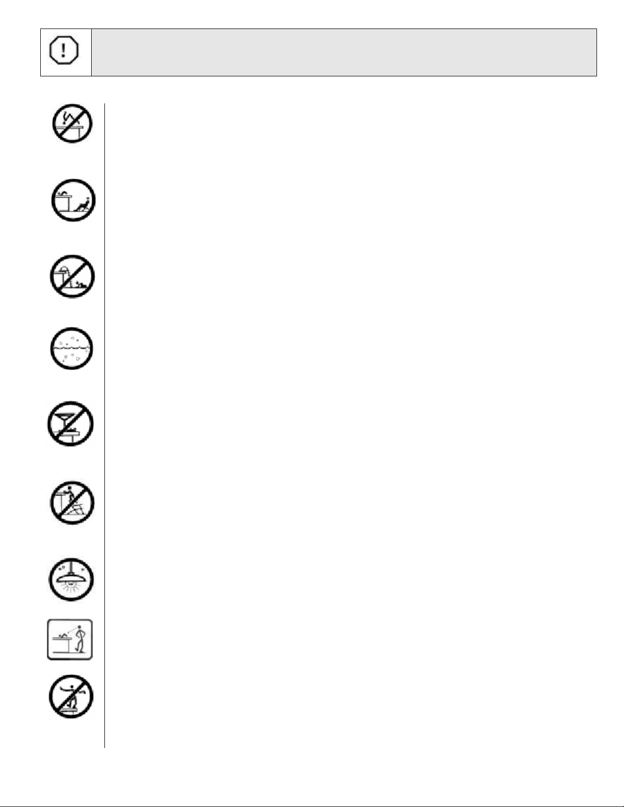
SAFETY GUIDELINES
- Do not install the swimming pool on balconies, terraces, roofs, areas prone to flooding or surfaces that are not
completely safe.
- It is important to place the swimming pool near a drain to prevent possible flooding. Remember that the pool is a
large water tank. If it is placed unevenly, pressure might cause its wall to collapse which would release a high
quantity of water and cause considerable damage to property or injury to any person/s nearby.
- This swimming pool is designed for private use only and not for commercial purposes.
- To avoid the risk of drowning or injury always supervise young children.
- Do not attach toboggans or springboards to the pool.
- Do not dive or jump headlong into the swimming pool from a ladder, a ledge or anywhere else.
- Do not lean, sit or walk along the edge, it has not been designed for this.
- Do not use the swimming pool if you have consumed alcohol, drugs or medication.
- Do not use shoes made of metal or sharp parts.
- Do not place tables, chairs or other objects near the swimming pool. They might give children easy access to the
swimming pool and cause injuries or drowning.
- Do not cut holes in the wall of the swimming pool in order to install lights or anything else that could cause serious
injury, electrocution or property damage. Failure to observe this advice may result in damage to the wall.
- Never use the swimming pool at night or with low visibility.
- The swimming pool’s water must be kept clean so that the bottom is always visible.
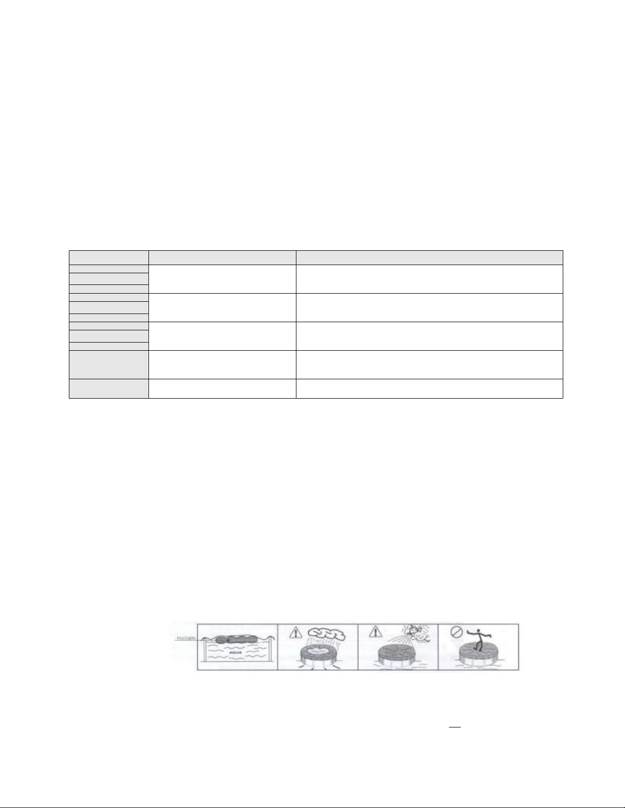
SAFETY TIPS (STANDARD REGULATION)
Monitor and act
- Close and constant supervision of children is a must.
- Designate one supervisor for safety and strengthen supervision when there are more people in the pool.
- Give lifesavers to people who cannot swim.
- Teach your children to swim as soon as possible.
- Wet neck, arms and legs before entering the water.
- Learn First Aid, especially First Aid for children.
- Forbid dipping and jumping into the swimming pool in the presence of children, as well as running and rough games
near the swimming pool.
- Do not authorise access to the swimming pool without lifesaver armbands or vests for children who cannot swim
well or are alone in the water.
- Do not leave toys near and/or in the swimming pool without monitoring.
- Always keep the water clean and unpolluted.
- Place water treatment products out of reach of children.
Prevent
Some equipment may help with personal safety, however it should not replace adult supervision.
Place:
- a fence around the pool whose gate is always closed;
- an accessible phone near the swimming pool;
- a rubber ring and a pole near the swimming pool;
- a manual or automatic protection cover properly installed and set and,
- an electrical device to detect falls or someone walking towards the swimming pool.
In case of accident
- Take the child out of the water immediately.
- Find help as quickly as possible and follow the instructions given.
- Replace wet clothing with dry clothing.
- Memorise the emergency phone numbers such as firefighters, Red Cross, Civil Defence, ambulance, medical
centre, etc. and place them near the swimming pool.
Attention: Filtering of water follows the installation standard NF C 15-100 which states that all electrical devices
located within less than 3.50 m. from the swimming pool and which are freely accessible must be powered with low
voltage, 12 volts. Any device powered with 220 V must be located at least at 3.50 m. from the edge of the pool.
Permission from the manufacturer must be requested in order to modify one or all the elements of the filtering
system. Very Important: Do not use saltwater for a filtration, voids the warranty.
SAVE THESE INSTRUCTIONS FOR FUTURE REFERENCE
ATTENTION: READ THESES INSTRUCTIONS CAREFULLY BEFORE PROCEEDING TO ASSEMBLE YOUR SWIMMING POOL.
REMIND ALL POOL USERS THAT THESE SAFETY INSTRUCTIONS MUST ALWAYS BE FOLLOWED-UP. KEEP THESE
INSTRUCTIONS FOR FUTURE CONSULTATIONS. ¡YOUR CHILDREN’S SAFETY DEPEND ON YOU! RISK IS HIGHER WHEN
CHILDREN ARE UNDER 5 YEARS OLD. ACCIDENTS CAN HAPPEN TO EVERYBODY SO IF INSTRUCTIONS ARE NOT
FOLLOWED MAY CAUSE HEALTH RISKS AND SPECIALLY IN CHILDREN!
4
ADVICE FOR THE CORRECT INSTALLATION OF THE SWIMMING POOL
1. Take your time and read the instructions carefully before installation. Follow them.
2. This pool must be installed outdoors on a firm, hard-wearing and levelled floor. (Read "Warranty").
3. This set has been conceived and designed to make installation easy. The final result will depend on the care and
attention given to the installation. If these instructions are followed, the swimming pool will be preserved in good
condition for a long time.
4. Check your local regulations and make sure to have a building licence, if necessary. Check the electrical and local
building regulations regarding the installation of above ground pools.
5. Remember that your pool is like a large water tank. If the pool is filled above the safety limits, the pressure can
collapse the wall, releasing a large amount of water and causing considerable damage to property or to any person/s
nearby.
6. This type of pool contains a large amount of water, therefore its weight is considerable. Take all possible safety
measures to prevent accidents. To calculate the approximate weight of your pool and its water capacity, take into
account that one litre is equivalent to one kilo.
7. Classify the components of the pool and make sure that you have the required tools before beginning installation.
8. Two adults are required in order to install the pool properly.
9. Installation time between two people is about 4 to 5 hours depending on the model.
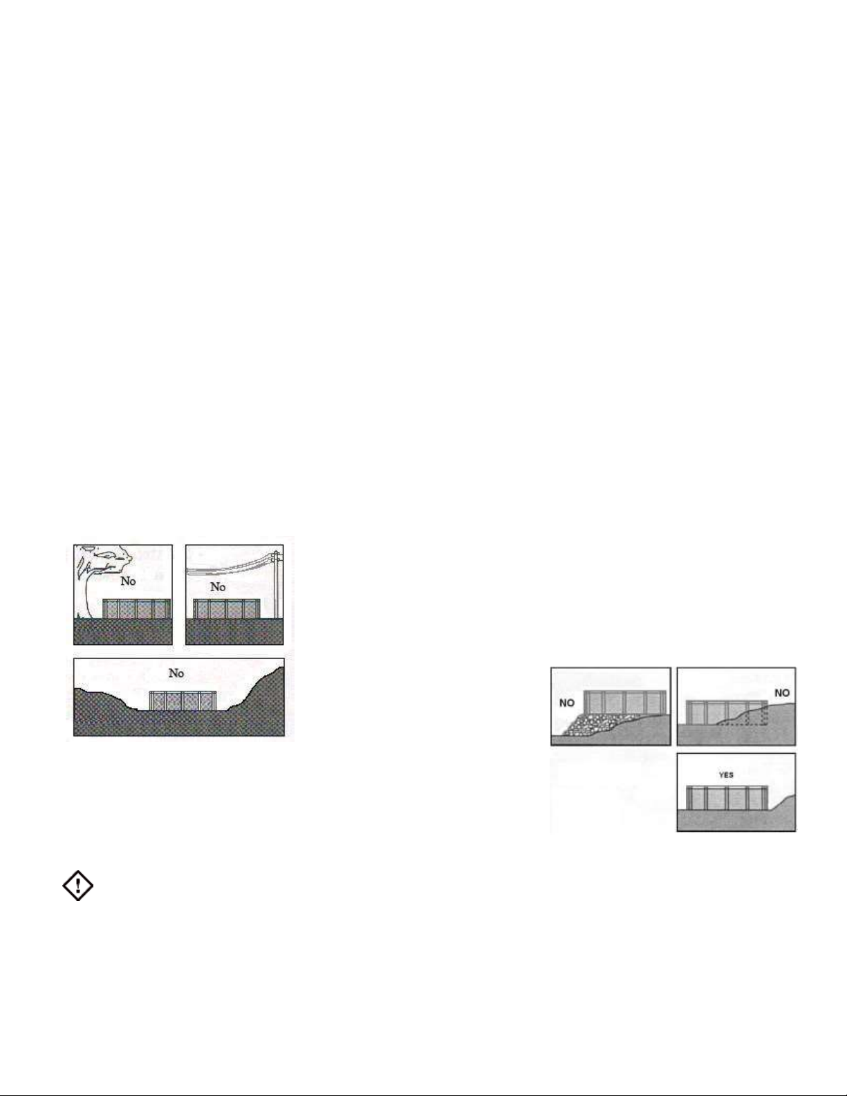
DETERMINING THE LOCATION OF THE POOL
Never install the pool below ground level. If you do not have a large or flat
enough surface area for your pool, then choose a place where you have to dig
as little as possible. To flatten the chosen area, it will be necessary to remove
the higher surface area in order to level it with the lowest level and not the other
way round.
Install your pool in a sunny area at least 6 metres away from any electrical
power point.
Do not install the pool underneath
electrical wires and make sure before
you start digging that there are no
underground electrical or phone
cables or gas pipes.
Do not install the pool under trees since branches, falling leaves and resin
can be a constant problem regarding water maintenance. The further away
from trees, the better for your pool.
Avoid installing your pool in areas prone to flooding or on soil recently treated
with chemicals.
Important: Choose carefully the location of your pool. Make sure that the distance to other adjoining facilities
(houses, fences, etc.) is appropriate. Make sure the ground is levelled. Contact the competent authorities in order to
receive information related to the installation of a swimming pool in your home

5
TOOLS (not included)
1.-A measuring tape.
2.-A spirit level.
3.-A marker pen.
4.-Adhesive seal.
5.-Cutter.
6.-Gloves.
7.-Pegs.
8.-Scissors
9.-A metal saw.
10.-A wrench.
11.-A slot-head screwdriver.
12.-A Torx® screwdriver.
13.-A file.
14.- A rake.
15.- A stake.
16.-Rope
LIST OF COMPONENTS
COMPONENTS: Remove and sort out the components of the pool before starting installation.
550x366x132
640x366x132
735x366x132
914x457x132
L
1
1
1
1
CH
1
1
1
1
TO
34
34
34
34
AR
34
34
34
34
TU
34
34
34
34
T1
10
10
10
10
T2
10
10
10
10
VER
10
10
10
10
PCM
8
8
8
8
EMB
10
10
10
10
EMBR
2
4
6
6
HOR1
0
2
4
4
HOR2
4
4
4
4
HOR3
8
8
8
8
PBS
11
12
13
17
PL
15
17
19
24
TO2
90
90
90
90
BU
20
20
20
20
SK
1
1
1
1
VR
1
1
1
1

6
LIST OF COMPONENTS THE MODULE
Keep this numbering and drawing below for retrofitting pool.
Ref.
Part/ item name
Ítem amount
550x366x132
Ítem amount
640x366x132
Ítem amount
731x366x132
Ítem amount
914x457x132
1
Base plate
2
4
6
6
2
Upper plate
2
4
6
6
3
Central column/pillar
2
4
6
6
4
Long U profile
2
4
6
6
5
Short U profile
2
4
6
6
6
Guide rail connector
2
4
6
6
7
Strap/ tensor
1
2
3
3
8
Screw 5,5x13
14
28
42
42
9
Screws base plate
6
12
9
9
10
Screws M5x15
4
4
4
4
11
Screws M8x 120 + nut M8
12
24
36
36
12
Right reinforcement plate
2
4
6
6
13
Left reinforcement plate
2
4
6
6
14
3 hole reinforcement
4
8
12
12
15
Screw M8x 110 + nut M8
4
8
12
12
16
Cap for nuts
4
8
12
12

7
PREPARING THE LAND FOR THE INSTALLATION
The area has to be COMPLETELY HORIZONTAL; there can be no unevenness in the land. VERY IMPORTANT: Never install the
swimming pool on top of expanded polystyrene plaques or similar. Use gloves and glasses during the installation.
Prepare the area, previous to installation, as specified in the following segment:
To mark the area where the pool is going to be located you will need: A peg or stick, a rope, a funnel (or bottle) and lime, flour or
similar. For better safety, use gloves and glasses.
- If you need to level the area or floor, do not refill the gaps. You have to remove soil from the more elevated areas of the
floor, to level them with the lower areas (and never the other way around), fig 1A. in any case, you will need to remove
roots, stones, grass and sharp objects.
- With the help of a rake or board and a level, you will need to level off the ground and cover the gaps with sand.
- With the help of a level and a strip of wood, check periodically that the ground is 100% leveled. Level the whole area at the
same level as the lowest area, fig 2.
fig. 1 fig. 2
Space required fig. 2:
Swimming pool: 550 x 366 x 132 - excavation: (X) length 610 x 518 width (Y)
Swimming pool: 640 x 366 x 132 - excavation: (X) length 700 x 518 width (Y)
Swimming pool: 730 x 366 x 132 - excavation: (X) length 790 x 518 width (Y)
Swimming pool: 915 x 457 x 132 - excavation: (X) length 975 x 610 width (Y)
COMPONENTS
Take out and classify all of the components of the swimming pool before starting the installation, if there is any components missing
within the assembly kit, you need to inform the after-sales service within 15 days after the purchase of the pool, otherwise the
guarantee will not cover this.
ASSEMBLY OF THE CENTRAL PILLAR
PRIOR TO THE ASSEMBLY
Very important: Always use gloves to work. The installation must be done between at least 2 people.
a) Place the short U profile (5), with the open sides heading upwards, to continue, slide
the long U profile (4) on top of the short profile, with the open sides heading
downwards, in order to form a sort of box, make sure that the holes on both profiles
match, but do not screw them, fig.3.
b) Now situate the central pillar or column (3) on top of the two profiles, as shown on
fig. 4.
c) Situate the reinforcement plates (both right and left) (12)(13) at each side of the central
pillar (3) as shown on fig. 5, the reinforcement plates have to be situated under the U
profiles, use 3 screws (8) to hold the reinforcement plates.
d) All holes have to match in order to situate the 8 mm x12 cm Screws and the 8 mm
nuts(11). Make sure that the reinforcement (14) is situated on both sides of the
ensemble. Use the 8mm x11cm screws and 8mm nuts (15) to attach the upper side of
the reinforcement plates of the pillars (12) (13), fig.6.
e) Once we have tightened all of the screws without forcing them, we have to situate the
guide rail connector (6) with one single screw (9), as seen in fig. 7. We call each of
these groups of united elements: modules.
fig. 3

8
fig. 4
ASSEMBLANCE OF THE STRAP
The modules have to be assembled in pairs, and have to be united between
them by a strap. You have to screw the strap to the end of the piece (4) using
the 5mm x 15mm screws and 6mm nuts (10), fig.8.
Take into account that the strap has to be attached to the lower part of the
profile (4), fig.9. in a way that the heads of the screws are in the upper side of
the profile and the nuts are in the lower side of the profile.
fig. 8
fig. 9
ASSEMBLANCE SRAIGHT AREA
After having assembled all of the modules, and after having connected them
with the strap you can now put them in their final location.
If your swimming pool has an odd number of straps (eg, a 730x366 pool with 3
straps) search for the centre of the previously leveled area and situate there
the first module, then situate the others at the same length.
Always keep the same number of modules at each side of the swimming pool
fig. 10 and fig. 11.
It is extremely important that all of the modules are straight, leveled and
perfectly lined up. Take your time to ensure that they are situated correctly.
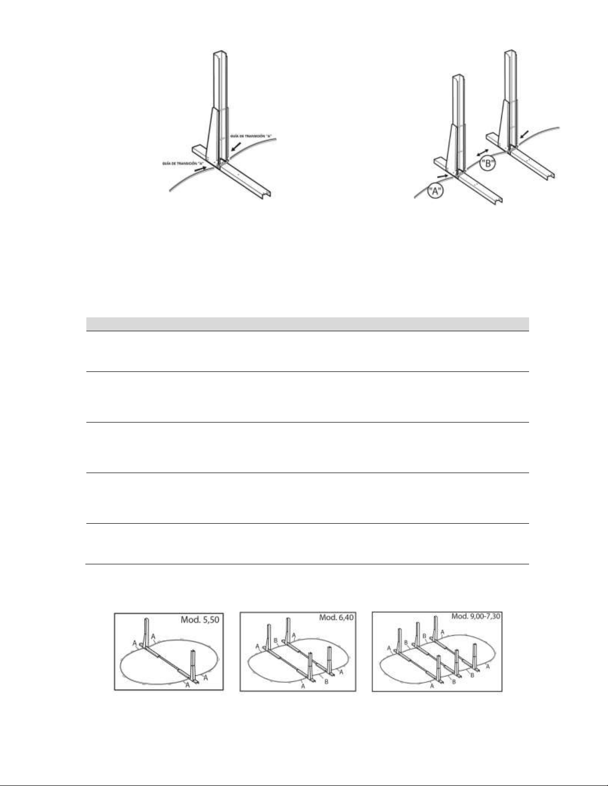
ASSEMBLANCE OF THE METALIC GUIDES
The following step would be to insert the transitional guide “B”, that
corresponds to the swimming pool model you have acquired (see the
transitional guide table) at both sides of the first module (take into account that
the oval model 550x366 has NO transitional guides “B”). This transitional guide
has to be situated inside the guide rail connector (6), fig. 12.
Situate the transitional guide in the guide rail connector (6), fig. 13, at each side
of the pool. Then continue to assemble the transitional guides “A”.
fig. 10
fig. 11
fig. 5 fig. 6
fig. 7
9
fig. 12
fig. 13
TRANSITIONAL GUIDES
Transitional guides have different colours assigned to them depending on the position they occupy. Use the following
table to choose the quantity and types of lower guides you need in order to assemble each swimming pool model you
may have acquired.
Transitional guide table
Model
Transitional guides “A”
Transitional guides “B”
Measures
550x366 cm.
850.015 x 4 –FUCHSIA
850.014 x 8 –YELLOW (PCM)
NOT APPLICABLE
± 1.420 mm. x 4
± 1.138 mm. x 8
640x366 cm.
850.021 x 4 –RED
850.014 x 8 –YELLOW
850.019 x 2 - WHITE
± 1.132 mm. x 4
± 1.430 mm. x 2
± 1.138 mm. x 8
730x366 cm.
850.021 x 4 –RED
850.014 x 8 –YELLOW (PCM)
850.017 x 4 - BLUE
± 1.132 mm. x 4
± 1.130 mm. x 4
± 1.138 mm. x 8
915x457cm.
850.019 x 4 –WHITE
850.022 x 8 –GREEN (PCM)
850.016 x 4 NO COLOUR
± 1.430 mm. x 4
± 1.370 mm. x 4
± 1.425 mm. x 8
1200x457cm.
850.019 x 4 –WHITE
850.022 x 8 –BROWN(PCM)
850.019 x 8 - WHITE
± 1.430 mm. x 12
± 1.380 mm. x 8
Here you may see the modules and location of the transitional guides “A” and “B”, fig. 13 (550 oval), fig. 14 (640 oval), fig. 15
(730/915 oval).
fig. 13 fig. 14 fig. 15

10
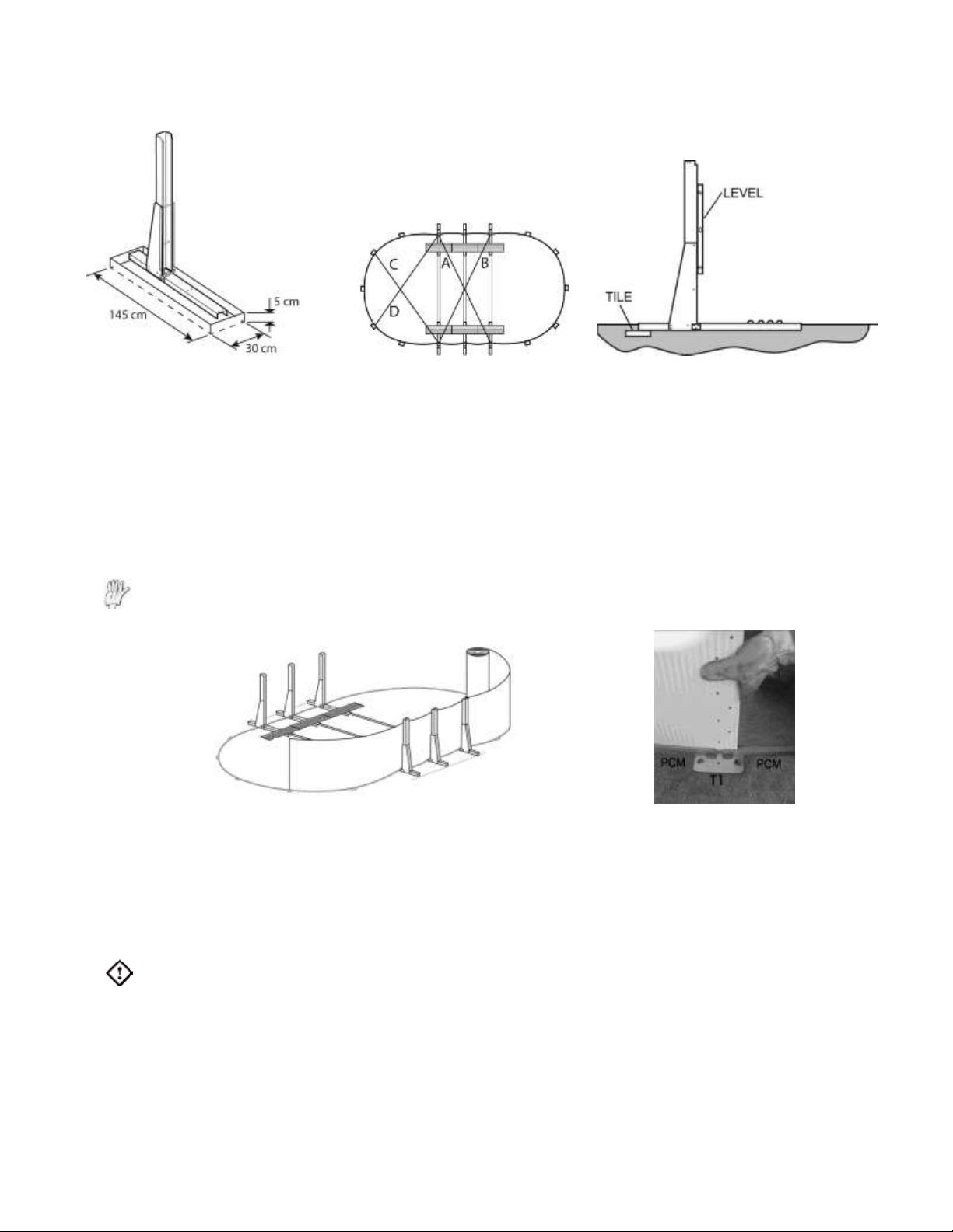
ASSEMBLANCE OF THE LOWER CURVED METALIC GUIDES PCM
Just after the transitional guides A, situate the T1 plate, followed by the lower curved guide (PCM), continue to do so
until the semicircle is closed, photo 3. The transitional guides A, have to go inside the T1 plate, photo 4, 5, leave a
space between the profiles.
BURRIAL OF THE MODULES
Once the structure of the base is completely finished, make sure that the sides are straight. Make sure that the
measures are correct, by measuring the distance from the exterior of the first module of the straight part, to the exterior
of the one on the opposite side.
These measures have to be taken from the lower part of the modules. This is to ensure a higher precision in the
measures taken.
It is extremely important that A=B and C=D, fig.17. if the measures are not equal, do not continue with the assembly, as
this may cause further problems in the installation.
ASSEMBLANCE OF THE BASE PLATE
Locate one 122cm base plate (1) in each module. The assembly of these plates must be done with the grooved side
facing upwards and the plain side facing downwards. These plates have two holes on one side, you have to make sure
that these holes are located towards the central column, fig.18.
The holes on the base plate have to match the holes on the U profile. Then, they must be attached between them by
the screws (9).
fig. 18
With spray paint, flour or lime, we have to draw the outline of one of the modules on the ground. Once we have drawn
it, we move the module to one side and remove the soil underneath with the help of a shovel (video:
https://www.youtube.com/watch?v=508QF1Pdulk). The depth of the hole must be around 5 cm., fig. 18, and must
be completely leveled. Once the hole is finished and leveled, we put the module inside it and make sure that it is
correctly leveled by putting a level on top of the module, fig. 19.
This process will need to be repeated on each of the modules of the swimming pool. You will then need to check the
measures with the measuring tape again, to make sure that the modules have not moved during the process (and are
still on their exact location) fig,18.
We will then situate a floor tile under each module, on the back side of the module fig.20. To do this, we incline the
module and we remove soil until the tile is leveled. Once the tile is installed, we check again that the module is leveled,
and we measure again fig, 19.
foto 1 foto 2 foto 3
11
To finish, we cover the tile with soil. We will then situate again the transitional guides “B” and “A”. The “B”transitional
guides must be settled in their place by removing or refilling with ground until it is leveled.
fig. 18 fig. 19 fig. 20
ASSEMBLANCE OF THE STEEL WALL (CH)
The installation has to be done between two or more people in a sunny non-windy day. It is extremely important to use
gloves and glasses during the installation to avoid any possible accidents with the steel edges. During the assembly,
do not fold the steel wall, and unroll it very carefully.
a) Situate the steel wall vertically (the interior label of the wall facing upwards) on top of a cardboard in the centre of
the circle, this will help you unroll the steel wall easier and will avoid any scratches on the steel wall. The opening
prepared to locate the skimmer is at the end of the steel roll.
Remember: to use gloves and glasses during the assembly of the steel wall to avoid any cuts.
fig. 21 foto 4
b) Without finishing to unfold it completely, start situating the wall in the opening you can find on the lower guides.
The beginning of the steel wall must be situated in a T1 base plate, photo 4. You would normally start with the
assembly of the wall on the base plate T1 situated at the center of the semicircle, to ensure that the opening
prepared for the skimmer is located next to it, once it has been completely unrolled.
c) Continue to check regularly that the wall is being well placed in the opening of the guides PCM. Check that the
transitional guides are well located too.
Advice: to avoid the walls falling towards the inside while installing the pool, seal the wall to the vertical
columns or pillars (1), photo 5.
d) Complete the circle with the wall and make sure that the holes on each end of the steel wall match each other,
then close with the screws (TO), making sure that the head of the screws is situated in the internal part of the wall,
and the washers (AR) and nuts (TU) must be situated on the outside of the pool, fig 22.

12
Very important: Put all of the screws in the steel wall, starting from the bottom and going towards the top end of the
wall, leaving the first hole on the top side with no screw. Press all of the screws using a screwdriver and a wrench to
press the nuts. If the installation and the fastening of the screws and nuts is not correct or complete, the guarantee of
the pool is lost.
e) Situate the PVC strap covering the heads of the screws (in the inside of the pool), in order to protect the liner from
the friction with the screws fig. 23. This strap must be strongly stuck in this area, if needed, use adhesive tape or
similar to stick it to the steel wall.
Before the installation of the liner, check that the guides form a geometrical curve. Check
with a meter that the pool has the correct measures before putting the liner.
fig. 23
a) f) Before the installation of the liner, put a layer of thin sieved
sand (no stones) on the interior area of the pool, with a 5cm
thickness. Make sure to cover all metallic parts of the pool that may damage the liner,
if not, the guarantee will be lost. Use a rake to make sure that the layer of sand is
leveled.
VERY IMPORTANT: Use clean sand (no stones or other objects) to cover the
perimeter around the inside of the pool, creating a triangular wedge (20 cm height, 20
cm base).This way we will avoid that the water pressure damages the liner, at the same time as we avoid that the liner
slides under the steel wall, helping a correct distribution of the forces. It is very important not to use thin grain sand, or
beach sand, fig. 24. Not putting this sand wedge cancels the guarantee.
TAPESTRY
Before installing the liner, it is advisable to situate tapestry TOI or artificial grass on the whole interior of the pool,
including on top of the sand wedge.
CORRECT LINER ASSEMBLY
In order to install the liner correctly, the liner must be perfectly centered, matching the swimming pool’s base. It is
extremely important to make sure that it has the minimum amount of
wrinkles possible.
1.- The central welding line that appears in the base of the liner must be
located in order that its ends match with the metallic plates that unite
the lower guides of the pool. The central welding line must be
completely centered.
2.- The distance from the liner to the steel wall must be equal in both
curves “A-A”, fig. 25, so we can adjust equally the liner wall in both curves.
foto 5 fig. 22
fig. 24

13
ASSEMBLY OF THE PVC LINING (L)
Before the assembly of the liner, you have to cut (with scissors for cutting metal), the hole that is prepared for the skimmer. You then
need to file down the parts you have just cut, to ensure that the metal cannot damage the liner.
fotos 6 foto 7 foto 8 foto 9
Important: install the liner between two people or more. The PVC used in our liners has been designed to resist solar exposure for a
long period of time. Depending on certain uses or climatological conditions, the characteristics of this material might vary slightly.
Never walk on top of the liner with shoes on or leave any tools on top of your liner. If the liner is punctured during the installation, its
guarantee is cancelled (check liner guarantee).
The liner is the most important and delicate piece of your swimming pool. Unpack your liner without using knifes or sharp objects,
and separate the liner from the rest of the pieces of your pool. Keep it in a safe place, where it cannot be damaged with any tools or
with the steel wall of your pool.
Assemble your liner on a sunny day (at least 20ºC). The liner has been developed based on a vinyl material which has a great
degree of flexibility (so it can adapt properly during the assembly of the pool), therefore it must be warm during the installation of
your swimming pool.
a) Locate the liner (L) in the centre of the pool, photo 10, and unfold it along the pool, photo 11. The central welding that unites the
base of the pool has to be perfectly centered. Important: as you unfold the liner, turn it around so the wrinkled part faces
upwards and the shinny part faces downwards.
b) Lift the liner wall, so you cover the upper edge of the steel wall of your pool and hold it in place with clothes pegs. Once the liner
has been located, it may have some kinds of bags or excess of material in the lower end. Correct this exceeding material by
pulling softly from the liner (from the outside of the pool). It is extremely important that the liner is centered, and that the central
welding on the base of the liner is situated in the center of the pool. You also have to ensure that it has the least number of
wrinkles possible. In order to reduce the number of wrinkles on the pools floor, you have to spread the liner towards the sides of
the pool, while the pool is being filled with water. Take your time with this step in order to reduce wrinkles.
Fill in the pool with more or less 2 cm. of water, and keep stretching and spreading the liner from the central welding and
towards the sides and upper side, so it gets as tense as possible, photo 13. Check that the water is distributed equally along the
pool. If the water forms puddles around the pool floor, it means there are still gaps on the land. If the water gathers at one side
of the pool, it means the area was not correctly leveled. If this is so, you would need to start again the whole process of the
installation, starting by leveling the area correctly.
c) Once the floor is free of wrinkles, fill the pool with water up to 30cm, DO NOT FILL IT IN COMPLETELY AT THIS POINT. The
pressure made by the water will stick the liner to the walls and floor.
d) At the same time, check that the liner is adapting properly to the walls and correct any exceeding liner by pulling smoothly from
the outside of the pool to reduce the amount of liner in the pool.

14
foto 10 foto 11 foto 12 foto 13
INSTALLATION OF THE UPPER PROTECTIVE SECTION (PL)
e) Remove the clamps while installing the protective profile (PL), fig. 24, over the liner and around the perimeter of the
pool.
f) Mark and cut off the protector surplus, photos 15 and 16
INSTALLATION OF THE UPPER SECTION (PBS)
Important: If your pool has included the decorated band, place it as per the decoration’s manual, before installing the upper profiles
PBS.
g) Position the upper section (PBS) on top of the protective section (PL) around the entire pool perimeter, photo 17.
h) Mark and cut off the protector surplus, photos 18 and 19. To prevent the pool wall from falling inwards, place the upper plate (5)
on the central columns (1).
foto 17 foto 18 foto 19
ASSEMBLY OF THE VERTICAL SECTIONS (VER)
a. Align the lower part of one of the vertical sections (VER) (1) with the two small tabs on the base plates (T1) (2). The
tabs must be on the inside of the vertical section, fig. 26.
b. Align the openings for positioning screws TO2 (3), on either side of the vertical section, making sure that they attach
to the holes in the T1 (2) plate tabs, fig. 26.
c. Place an upper section (T2) (4) onto the top edge of the pool and on a vertical column (VER), with the tabs on the
inside of the section, fig. 27.
d. Align the openings for positioning screws TO2 (6), fig. 27, in the three holes in the vertical section, making sure they
fit into the T2 (6) tab holes.
e. Repeat steps a, b, c, d in the other sections around the pool.
foto 14 foto 15 foto 16

15
fig. 26 fig. 27
THE ASSEMBLY OF THE HORIZONTAL PROFILES (HOR 1, 2, 3)
a)Photos 20 and 21, install the upper profiles HOR1 (straight cut) on top of the central pillars, locating the extremes on
top of the upper plate, fig 28. Situate and screw the screws without pressing them yet. The 550x366 pools do not
have an upper HOR1 profile, so you need to start with the HOR 2 profile (section b).
b)Locate all of the upper profiles HOR2 on top of the vertical columns, on top of the T2 plate, photos 22 and 23. Match
the holes on them and screw the screw without pressing them yet.
c) Adjust the upper profiles until you locate them together, but without putting one on top of the other. Press all of the
screws, photo 23.
fig. 28
foto 22
foto 23
Important: If any of the vertical columns (VER) is not straight with respect to the ripple wall, adjust the vertical column giving light
hammer blows to a piece of wood on the base plate (T1). If the top of the vertical column is not aligned it must also be adjusted.
ASSEMBLY OF THE TOP HUB CAPS (EMB y EMBR)
Align a trim (EMB) in the curve on the ends of two top profiles. Hook the trim underneath the internal edges of the top profiles,
photo 23 and pull towards you, photo 24, hooking the trim on the outer part, photo 25. Repeat with the other trims.
Align a trim (EMBR) in the straight part, hook the bezel below the inner edges of the top profiles and pull towards you, hooking
the trim on the exterior part.
LAST DETAILS
- You must place the Warning Sticker in a visible place, fig. 29, 30.
foto 20
foto 21
foto 23 foto 24 foto 25

16
- Place the cap (BU) to the ends of the screws at the bottom of the profiles, fig. 31.
- Situate the tips (16) on the on the nuts of the modules, fig. 32.
- Attach the ladder according to the assembly instructions, put it in a place intended for entry and exit from the pool and if possible
visible. Remove the ladder after use.
- Assemble the filtration unit following the instructions. The filtration equipment must be separated from the pool by at least 3.5
meters once it has been connected to the pool by hoses.
INSTALLING THE RETURN VALVE (VR) The return valve is an element which brings back the filtered water from the
filter system, fig. 33. Important: Place Teflon on all threads. Teflon excess may
break the components. Remove the rear fitting of the return valve and place
Teflon, screw all the way.
1) Once the water is at +/- 10 cm., fig. 34,
below the lower edge of the valve, mark the
hole in the liner with a felt pen and with a
sharp blade, cut the liner carefully into a
cross-shape from the inner wall of the pool
towards the outer wall, without going past the
punched hole.
2) On the return valve (A), once the seals are placed, the rubber (B) is introduced into this pre-cut hole, from the interior wall to the
exterior wall. Cut the piece of liner that hangs on the external side.
3) Place the rubber washer (C) on the outer wall, put Teflon on the threads and tighten firmly with the large nut (D) inserting Teflon
and the return hose (E), which runs from the filter system to the return valve (a) and secure it with a clamp (H).
For better filtering we advise you to direct the water. In order to do this, you will have to loosen the washer (AR), move the
swivel ball (BO) slightly upwards to one side of the pool and tighten the washer (AR). In this way impurities will be directed towards
the skimmer.
INSTALLING THE SKIMMER (SK)
Keep on filling the swimming pool with water up to 5 cm below the skimmer hole, fig. 35. With a felt pen mark on the liner the
square hole for the installation of the skimmer and cut the piece of liner marked with a sharp blade.
Place the double rubber washer (Z) on the steel wall. The steel wall and liner must go inside the grooves of the washer. Next,
install the skimmer frame with the screws. Make sure that all the holes are lined up (washer, hole and skimmer). Fix the holes with
the screws one after the other until a perfect match is made, but do not tighten them up
too much. Start fastening and finally tighten the screws firmly following the same order, fig.
36. Cover the frame (M) threading with Teflon and
fasten it up firmly into the skimmer. Fix one hose end to
the frame (M) with a clamp (H). Connect the other hose
end to the filter water inlet and tighten with a clamp.
It is important to use Teflon for all threadings so as to
make sure that it is waterproof. Install the gate (P) with
a screwdriver. Finally, place the basket (S) inside the
skimmer and the lid (V) on top of it.
WATER MAINTENANCE
All swimming pools need chemical treatment to maintain the sanitised and crystal
clear water. Check with your chemical products supplier to determine which are best for
your needs. Water treatment procedure is not the same everywhere since it depends on
fig. 29
fig. 30 fig. 31 fig.32
fig. 33

17
the water quality in each region.
WARNING: An incorrect treatment may cause water pollution which can result in infections, poisoning or disease.
The best water quality is obtained by using the right treatment. To prevent the growth of algae and bacteria, use bactericide,
algaecide, water pH correctors and flocculants (except for cartridge filters). Apply the first chlorine treatment within 24 hours of filling
in the pool.
Never add chemical products directly to the water. Chemicals must be diluted before being introduced into the water. Otherwise
the liner could be damaged. However, it is easier to keep the water clean than to clean already polluted water. Use your filter
frequently.
Water maintenance is the most important factor in making your pool liner look excellent and last for a long time. Therefore,
follow the instructions in the filter manual. The filter capacity must be high enough to filter the water of the pool 3 times every 24
hours. The filter must be connected even when there is nobody in the pool.
Make sure to check the water at least once a week, to keep the pool in optimum condition.
Make sure that you do the following on a frequent basis:
- Analyse the water pH and make sure it is between 7.2 and 7.6.
- Analyse the chlorine level and make sure it is between 0.5 and 2 grams per cubic meter.
- Remove any leaves and insects from the water.
Make sure that you do the following on a weekly basis:
- Add the correct maintenance quantity of algaecide.
- Add anti-calcareous product if lime is formed or the water is hard.
- Use flocculants to improve filtering (except when using a cartridge filter).
SAFETY MEASURES FOR HANDLING CHEMICAL PRODUCTS
The following precautions must be followed when handling chemical products:
- Use gloves to protect your hands and a mask or goggles for eye protection.
- No smoking where the products are stored or used. Many products are flammable.
- Wash your hands and face after using the products.
- Store the products in a dark and dry place. Do not leave the products in the sun.
- Make sure that the containers are closed. Tighten their caps or lids.
- Do not leave the products within the reach of children. Make sure that the products are stored out of reach in a safe place.
- Do not re-use empty containers.
- Keep the products in their original containers.
- Do not remove the labels from the containers.
- Make sure that the storage area for chemical products has proper ventilation.
- When raining, increase the amount of chlorine and anti-algae bactericide.
- When adding water to the pool, check again the chlorine and anti-algae bactericide level.
- Keep the place where the chemical products are stored well ventilated.
POOL MAINTENANCE
After your pool has been completely installed, follow these instructions to keep it clean and in good condition.
- Liner –Regularly check for leaks in the liner. Use the repair kit for small repairs on the liner.
- Pool wall –Keep it clean, using a neutral pH detergent. Do not use abrasives, chemicals or cleaning solutions.
Rinse out silt chemical products used for water treatment straight away. Coat all visible screw heads with transparent outdoor
varnish.
Check the metal parts for rust, at least once a year. Coat all scratches and rusted areas with an anti-rust primer. Follow the
instructions for applying the paint.
At the end of the season, drain the water until the water level is 30 cm. Remove the upper part of the liner and check for
possible rust on the inner side of the pool wall.
Pay special attention to leaks in the filter and outlet holes. Leaks must be repaired straight away.
18
SHOCK CHLORINATION
Destroys quickly and efficiently all microorganisms, bacteria and fungi if the chlorine level is raised up to 20 ppm approximately.
Shock chlorination is recommended in the following cases:
a) At the beginning of the bathing season.
b) Depending on special weather conditions (i.e. storms, rain, etc).
c) In case of intensive use of the swimming pool.
Cleaning the bottom of the swimming pool by aspirating: only for pools with skimmer and filter with engines 6, 8, 10 y
15 m³. Connect the end of the hose to the brush and immerse it in the water for the hose to get filled up. Connect the other end of
the hose to the aspiration cover and put it on the basket of the skimmer. Start the filter system in Drain Off mode and start cleaning
the bottom.
Cleaning the bottom of the pool with a venturi sweeper jet: Connect a hose to the head of the venturi sweeper jet and
immerse it in the swimming pool. Open the tap with a normal pressure and the venturi sweeper jet will start working. The water
bounces on the ground producing an upwards flow that collects and deposits the dirt inside the filter-bag.
Problems
Causes
Solutions
Murky water
Poor filtration. High pH. Excess of
organic residue.
Backwash the filter. Add a flocculating agent with a dispenser. Carry
out a shock chlorination except in cartridge filters.
Green water
Algae formation.
Brush the bottom and the wall of the pool. Analyse the water’s pH and
adjust to between 7.2 and 7.6. Carry out a shock chlorination and add
extra anti-algae bactericide.
Brown water
Presence of iron and manganese.
Analyse the water’s pH and adjust to between 7.2 and 7.6. Carry out a
shock chlorination.
Lime deposit
Water calcium salts.
Analyse the water’s pH and adjust to between 7.2 and 7.6. Add anti-
calcareous product once a week.
Eyes and skin
irritation
Imbalanced pH. Excess of organic
residue.
Analyse the water’s pH and adjust to between 7.2 and 7.6. Carry out a
shock chlorination.
CARE DURING THE WINTER MONTHS
If we decide to keep the pool up during the winter, you must follow these guidelines at the end of the season to prepare your
swimming pool.
a) Check all joints and screws.
b) Check possible and treat rusted areas.
c) Clean the liner with mild soap and water in case of leakage repair them, never with abrasive products.
d) Remove all accessories, including the ladder, clean it with fresh water.
Disconnect the hose from the debugger and return valves (not remove the skimmer or the valve input and output) close the
skimmer and return valve with plug attached. For pools with inlet and outlet water, let the water level 15 cm. below the upper profile.
For pools with skimmer and valve outlet, the water level must be below the skimmer 5cm. In both cases, do not leave empty pool.
Drain cleaner sand or remove the cartridge, clean, dry and store in a dry place.
e) Protect the pool with a cover to keep the flat roof, put an inflatable element or float between water and cover to prevent rain or
other weather elements from damaging the liner.
Commissioning again, remove the cover, install the filter, if necessary empty the pool and clean the liner with no abrasives, fill the
pool with water and make a shock chlorination, connect the debugger at least 8 h. uninterrupted.
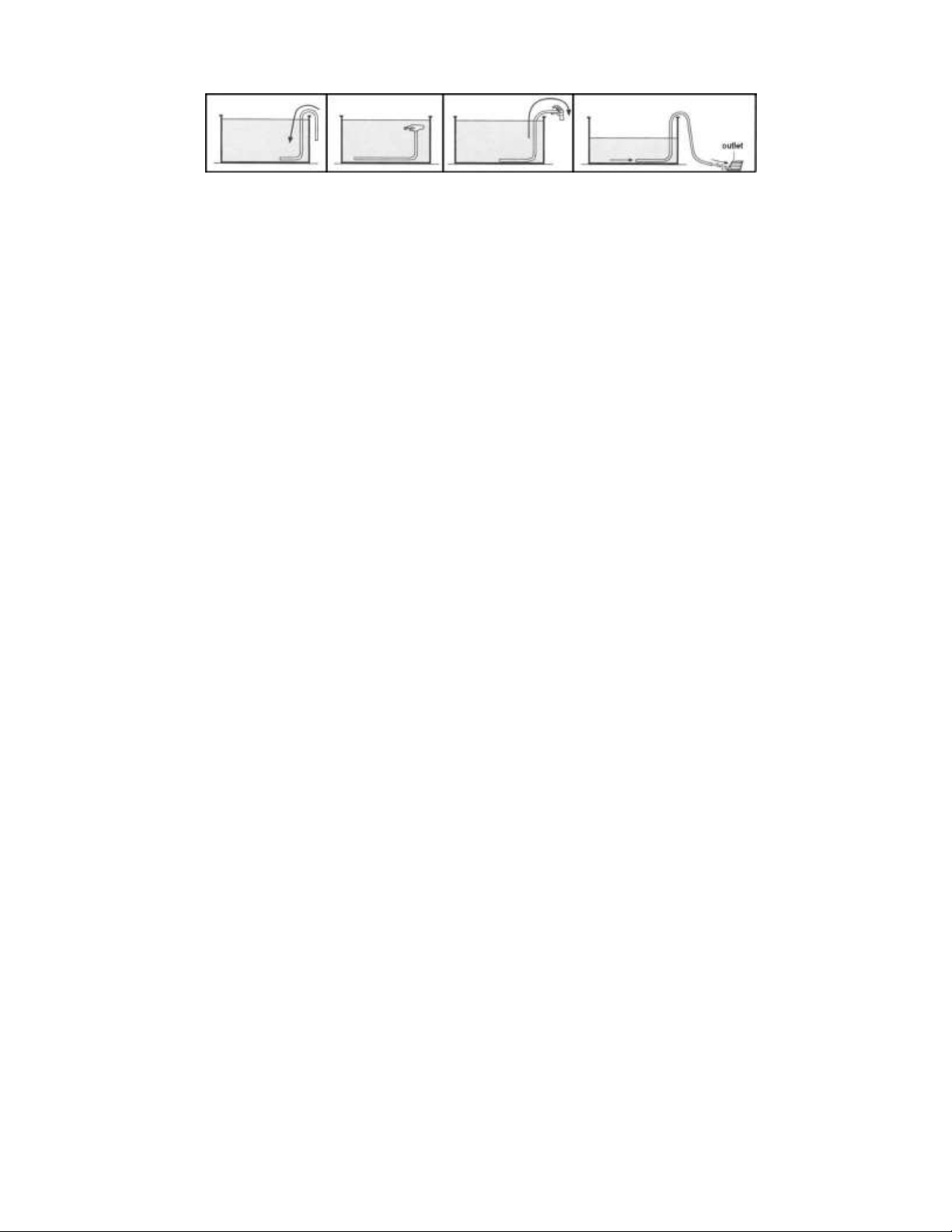
EMPLYING THE POOL
First check the filter instructions to make sure that your filter has the Option to Empty.
Use the Communicating Vessels Principle: first completely submerge a hose in the pool until it is full of water. Then cover one end
with your finger and take it out of the pool. Water will start to come out. Make sure to keep the other end of the hose submerged in
order to empty the pool.
19
Once you empty the pool, carefully dismantled in reverse order of the installation in order not to damage or deform the pool.
Check that all parts are clean and dry before storing. Before storing the liner, clean with mild soap and water, do not use abrasive
products, remove all impurities and dry with a cloth or paper towel in order to keep it in top condition and prevent odors and
moisture, fold the liner and save in a dry and protected from the sun.
In the event that an item is damaged, replace it as soon as possible with original accessories TORRENTE INDUSTRIAL S.L.

20
WARRANTY ¤ WARRANTY¤WARRANTY ¤ WARRANTY
GENERAL CONDITIONS
The seller guarantees that this product is in perfect condition at the moment of delivery.
The period of this warranty is of (2) years and it will be calculated from the moment of delivery.
If there is a lack of compliance and the buyer notifies it within the guarantee period, the seller must repair or replace
the product at the place deemed appropriate unless this is impossible or unfeasible.
If the product cannot be repaired, the buyer can request a proportional reduction in the price of the product or if the
lack of compliance is considerable, the termination of the sales agreement.
The replaced or repaired components will not increase the period of the original product’s warranty. However they
will have their own warranty period.
In order to make effective this warranty, the buyer will have to show both the date of purchase and of delivery of the
product.
After more than 6 months since delivery, if the buyer claims lack of compliance of this product, he/she will have to
show the origin and existence of the alleged defect.
The present warranty certificate does not limit or prejudices consumer rights that follow national regulation by legal
imperative.
SPECIFIC CONDITIONS
This warranty covers the products in this manual.
This warranty certificate will apply only to countries in the European Union.
For the effectiveness of this warranty, the buyer must strictly follow the manufacturer’s instructions included in the
document accompanying the product, when this is applicable according to the range and product model.
When a set of dates has been established for replacement, maintenance or cleaning of certain pieces or components of
the product, this warranty will only be valid when these dates have been followed correctly.
LIMITATIONS
This warranty will only apply to purchases made by consumers, meaning, a buyer who has acquired the product with no
commercial purposes.
There is no warranty for wear and tear of the product. Regarding pieces, components and/or other expendable goods
such as batteries, light bulbs, etc., this will be treated according to the documents accompanying the product in each
case.
The guarantee does not cover cases in which the product: 1. –has been misused. 2. –has been repaired, maintained
or manipulated by a non-authorised person. 3. has been repaired or maintained with non-original pieces.
When the lack of conformity of the product is due to an incorrect installation or start-up, this warranty will only be
effective when such installation or start-up was included in the purchase agreement of the product or when it has been
done by the seller or under its responsibility.
ESTABLISHMENT STAMP
TORRENTE INDUSTRIAL S.L.
C/ Sierra Calderona, nº 1
46180 Benaguacil ¤ Valencia ¤ España
Teléfono: 96 273 01 36
Web.: www.piscinas –toi.com
Table of contents
Other TOI Swimming Pool manuals


Popular Swimming Pool manuals by other brands


SmartPool
SmartPool SolarArc S202 Installation and instruction manual

Astral Pool
Astral Pool Piscine Laghetto Pop! Series Assembly instructions

Blue Wave
Blue Wave NT6130 instruction manual

Bestway
Bestway 57241 owner's manual

SUMMER WAVES
SUMMER WAVES Quick Set Ring Pool owner's manual

Intex
Intex Prism 128712GN owner's manual