Tokyo electric CS6100P User manual

O
PERATION MANUAL
CS6100P
For customer Use:
Enter below the Serial No. which is located on
the rear panel of the camera control unit.
Retain this information for future reference,
Model No _CS6 100P
Serial No.__________
TOKYO ELECTRONIC INDUSTRY CO., LTD.

Thank you for purchasing the teli CS6100P television
color camera featuring compact and light weight.
To take best advantage and gain the most service from
your camera, read this operation manual carefully and
throu
g
hl
y
.
WARNING:
TO PREVENT FIRE OR SHOCK HAZARD, DO NOT EXPOSE THIS
APPLIANCE TO RAIN OR MOISTURE.
This equipment should be used with DC 12 V only.
Do not use any other power source.
INFORMATION
This equipment generates and uses radio frequency energy
and if not installed and used properly, that is, in
strict accordance with the manufacturer's instructions,
may cause interference to radio and television reception.
If does so, which can be determined by turning the
equipment off and on, the user is encouraged to try to
correct the interference by one or more of the following
measures:
Reorient the receiving antenna;
Relocate this equipment with respect to the
receiver;
Move this equipment away from the receiver;
Plug this equipment into a different outlet so that
this equipment and receiver are an different branch
circuits.
If necessary, the user should consult the dealer or an
experienced radio/television technician for additional
suggestions.

CONTENTS
Page
1, FEATURES 1
2, PRECAUTION 1
3, CONTROLS AND ADJUSTMENTS 3
3-1 Camera head 3
3-2 Camera control unit 4
4, CONNECTIONS 9
5, SUPPLEMENTAL INFORMATION 13
(1) Color temperature 13
(2) White balance 13
(3) How to get good color 13
(4) Color temperature of various 14
artificial lighting
(5) CCD image sensor 14
(6) Smear 15
(7) ASC and AGC 15
(8) Lenses 15
6, TROUBLE-SHOOTING GUIDE 16
7, SPECIFICATIONS 17
8, CONSTITUTION 19
9, APPERANCES 20
(1) Camera head 20
(2) Camera mounting kit 20
(3) Camera control unit 21
10, MAINTENANCE 22

1, FEATURES
* Compact and light weight
* Available External sync-operation
* Provided 3 kind of video outputs of a PAL, Y/C and RGB.
* Equipped with both ASC (Automatic Sensitivity Control)
and AGC (Automatic Gain Control) which allows wide
dynamic range from bright to dark subjects.
* Equipped with an electronic shutter for fast moving
subjects for better definition picture.
2, PRECAUTION
(1) This equipment should be used with DC 12V only.
To prevent electric shocks and fire hazards, do not use
any other power source.
(2) The CS6100P is designed to be used with PAL color
television signals. It cannot be used for playback with
a television of a different standard.
(3) Please handle the equipments carefully.
(4) Do not point your camera lens directly into sunlight or
strong artificial light. This might cause irreparable
damage to the image sensor.
Also, be sure to use the lens cap when the camera is not
in use.
(5) Do not expose the camera unit to high temperatures. For
example, do not place it near a stove for long periods,
or in direct sunshine or in a car in hot weather.
Heat may cause some malfunction.
(6) Keep the camera clean. Dust can damage the camera and
cause trouble in moving parts.
Take particular care to avoid the entry of Sand or grit
when changing the camera lens.
(7) Avoid jolting the equipments or exposing it to vibration.
(8) Never attempt to dismantle the equipments.
(9) Avoid folding or stretching the camera cable or other
connection cable between equipments.
(10) When the cabinet is dusty, clean by gently wiping with
a soft cloth. And avoid the use of strong cleaning
agents such as benzine or alcohol as they may damage the
cabinet.
-1-

-2-
IMPORTANT
The camera control unit provides four screw holes
at the bottom chassis which are used to mount for
anything of a rack. Do not use longer screws inserted
over 3.5mm from the bottom chassis when the camera
control unit is installed to anything board.
Because there is a printed circuit board closed to
the bottom chassis, may cause damage it.
Bottom chassis provides
four screw holes of 2 6mm(ISO)
A part of camera control unit
printed wiring board

3, CONTROLS AND ADJUSTMENTS
Get to know the name and function of every part of your
camera. That way, you can take advantage of every
applications to take beautiful pictures.
The body and accessories shown below related to CS6100P.
3-1 Camera head
(1) Iris ring (Aperture ring) for use at manual operation.
To reduce aperture, rotate the iris ring toward CLOSE
(clockwise).
To increase aperture, rotate the iris ring toward OPEN
(counter clockwise). Adjust the lens aperture according
to the amount of light entering the lens so that correct
exposure is obtained.
(2) Focus ring
Take the focus with the ring to focus for the sharpest
picture.
* No lens is included in the provided accessories, make
choice of the most appropriate lens, according to your
system as necessary.
Camera head
mounting kit
-3-
Camera head cover
Camera cable
Lens for CS6100P
Camera head
(3)Camera cable
Provided camera cable is 3 meters in length. Join to the
optional extension camera cable (7 meters) as necessary.
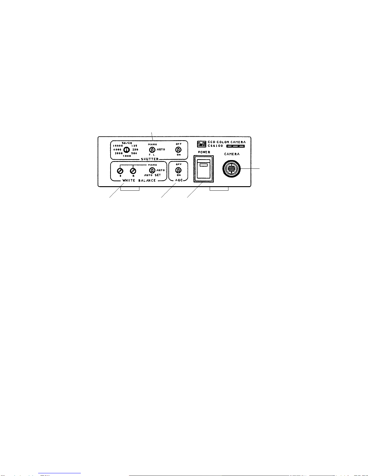
3-2 Camera control unit (front panel)
SHUTTER
WHITE BALANCE AGC POWER
CAMERA
(1)"POWER"
A power on/off switch. When power is turned on, the
pilot lamp on the power switch will light.
(2)"AGC"
AGC ON/OFF switch.
The AGC (Automatic Gain Control) switch is to increase
sensitivity electrically in low-light situations.
Set "AGC" switch to "ON" when illuminationis not
sufficient on the subject. Normally, put it "OFF"
position.
(3)"WHITE BALANCE"
The picture taken with a camera is sometimes adversely
influenced by the quality of the light illuminating the
subject. To obtain fine color images, it is necessary to
adjust color balance (white balance) in the camera's
video circuit depending on the quality, or color
temperature, available from such illuminating sources,
e,g. morning, midday, evening, and fluorescent lamp.
When making adjustment on "WHITE BALANCE", select any
one of "AUTO SET"/"AUTO"/"MANU".
-4-

* "AUTO" (Automatic follow-up system)
The purpose of this white balance of "AUTO" is for a TV
monitoring system, which installed to shoot a scenery
with wide angle. This automatic white balance adjust-
ment is performed by the detection of the average
picture levels of red(R), green(G), and blue(B) signals
picked up from the subject while they are balanced.
Under the proper condition, this incorporated function
is automatically compensated and follows up the white
balance for color temperature even when the camera is
panned during shooting, changed the color temperature of
a light source or changed ambient condition while "AUTO"
position.
However, this control system is not always perfect, for
example, under a fluorescent light or when shooting and
closing up a subject with large colored area, this
control system cannot work properly and also cannot
obtain good color-imetry (color reproduction).
The purpose of the "AUTO" position is for TV monitoring
system for a scenery with a wide angle. If white balance
adjustment is not possible, use "AUTO SET" position.
* "AUTO SET" (Data holding)
Turning to "AUTO SET" after adjusted the white balance
for one or two seconds at "AUTO" position taking white
subject, e.g. white wall or white paper, the data of the
white balance will be held. And the white balance is
not change anything even if changed the illumination on
subject and the data will be held for about 5 hours
backing up the data.
Normally, set it "AUTO SET" position.
If you shoot more than 5 hours after the last white
adjustment, or when lighting conditions change,
re-perform white balance adjustment.
-5-

* "MANU" (Manual)
Turning to "MANU" position, take a white object such as
a white paper or white wall all over the screen and
adjust the white balance with the knobs of (R) and (B)
while watching the color monitor. For more information
on color temperature and white balance, refer to the
supplemental informations of pages 13 and 14.
(4)"SHUTTER" (Electronic shutter)
Switches for an electronic shutter. The camera
incorporates an electronic shutter with a variable speed
function ranging from 1/50 to 1/10,000th seconds, allow
ing of a subject moving at a high speed.
Usually, put "OFF" position at the left side, which is
set a shutter speed of 1/50 sec. When required
electronic shutter, put it "ON" position and select any
of "F.L"/ "AUTO"/"MANU" on the camera control unit.
* "F.L" (Flickerless)
Where the illumination of fluorescent lamps are used in
the power frequency area of 60 Hz, a flicker may appear
on the picture. And if turned to "F.L" position, it will
be set the shutter speed 1/120 sec., resulting in
decrease the flicker on the picture.
* "AUTO" (Automatic Sensitivity Control)
This camera is provided with an automatic sensitivity
control which adjusts the shutter speed according to the
amount of light entering the lens so that correct
exposure is obtained even when illumination of the
object changes. Fixed shutter and manual control are
also possible.
* "MANU" (Manual)
When a subject moving at high speed is shot by the
camera, put it "MANU" position. And select any one of
shutter speeds of 1/50, 1/125, 1/250, 1/500, 1/1000,
1/2,000, 1/4,000, 1/10,000 sec. as necessary.
-6-

For more information on electronic shutter and ASC
(automatic sensitivity control), refer to the supple-
mental informations-of page 15.
(5) "CAMERA"
This connector is used to connect between camera head
and camera control unit by camera cable.
3-3 Camera control unit (side panel)
Following adjustments are located at the side panel on
the camera control unit.
GAMMA SYNC H SC
(1) "SC" (Sub carrier phase)
When synchronized by an external VBS, the color phase
"SC" must be adjusted. After making rough adjustment
with "COARSE" switch, make fine adjustment with "FINE"
knob.
(2) "H" (Horizontal drive pulse phase)
When operated by external sync., adjust the horizontal
phase with this knob "H".
(3) "SYNC" (Sync pulse phase)
When the RGB output signal provides sync pulse, turn it
"ON" position. If not, put it "OFF" position.
-7-

-8-
(4) "GAMMA" (Gamma correction)
Generally, TV camera provides gamma correction in the
Video-process amplifiers which make up opposite side for
non-linear characteristics of image signals based on
CRT's electron gun in TV receiver, and the total
performances of the video system have linear (gamma : 1)
Usually, use the gamma correction "ON" position which
set the standard camera gamma-value of 0.45.
And if required gamma "OFF" (gamma value : 1.0) with the
system, turn it to "OFF" position.
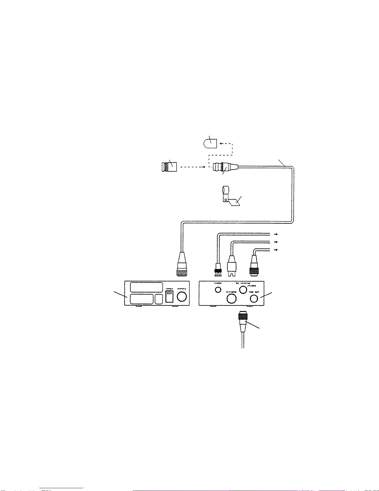
4, CONNECTIONS
When install the CS6100P camera to your system, you have
to connect between equipments.
4-1. Typical connection.
Camera head cover
Lens for CS6100P
Camera head
Camera head
mountin
g
kit
VBS OUT
Y/C OUT
RGB/HD/VD/SYNC OUT
Camera control unit
(rear panel)
DC input connector
Camera control unit
(front panel)
BNC
S
-
terminal
-9-
Camera cable
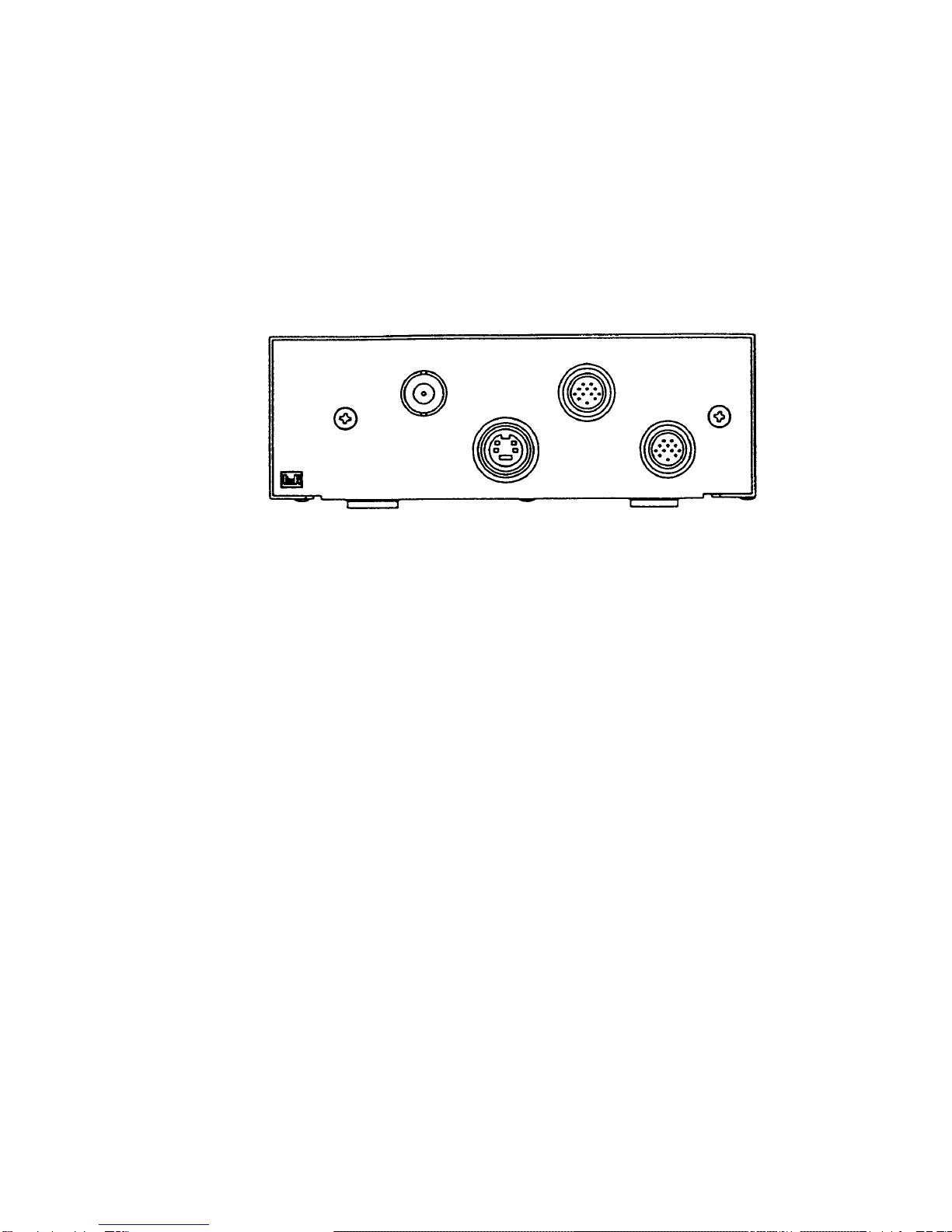
There are four connectors of "RGB OUT", "S-VIDEO", "VIDEO" ,
and "DC-IN/SYNC/VIDEO" at the rear panel on the camera
control unit.
Camera control unit rear panel
4-2 "RGB OUT"
The connector is composed of 12 pins, and the three
primary color signals and some drive pulses are output.
(1) RGB video outputs
R, G and B video signals are output individually from
pin 1-2(GND) for R, 3-4(GND) for G and 5-6(GND) for B on
the "RGB OUT" connector. They can be connected the
use of the monitor provided R,G and B individual input
terminals.
(2) Pulse outputs
Use them when other equipments required pulses (HD, VD,
SYNC) to be synchronized with the camera.
When the external sync-operation, the pulses of HD,VD
and SYNC are regenerated inside of the camera control
unit and are output. When no pulses from outside (at the
internal sync-operation), HD, VD and SYNC generated
inside are come out together from the "RGB OUT".
-10-
/
VIDEO
RGB OUT
VIDEO
CS6110P
SERIAL No.
TOKYO ELECTRONIC INDUSTRY CO.,LTD
DC IN/SYNC
S-VIDEO

pin No. output
1 R VIDEO OUT
2 R VIDEO GND
3 G VIDEO OUT
4 G VIDEO GND
5 B VIDEO OUT
6 B VIDEO GND
7 SYNC OUT
8 SYNC GND
9 HD OUT
10 HD GND
11 VD OUT
12 VD GND
female
12 pin connector for
"RGB OUT" pin
arrangement on the
camera control unit
4-3, "S-VIDEO" (S-terminal)
Y (lumminance signal) and C (chrominance) are output
from the "S-VIDEO" individually.
The employment of an S-terminal allows reduction of
cross color, dot disturbance, and color blurring that
may occur especially during picture editing, compared to
the PAL composite video signal. Use the equipments with S-terminal
in the system.
4-4, "VIDEO"
The PAL composite video signal is come out from this
connector which is employed BNC type.
4-5, "DC IN/SYNC/VIDEO"
The connector is combined with DC 12V input, and some
other, and recommended for an image processer system.
They are composed of 12 pins, and used as followings.
(1) DC 12V input
Connect pin number 2 and 11 for DC 12V (HOT) and pin 1
and 10 for GND.
-11-

(2) Composite PAL video output (VBS) is output from 4 (HOT)
and 3 (GND).
(3) Input pulses for external sync. When required external
sync-operation between other equipments, use any one of
pulses for HD/VD, VBS or SYNC. And input HD pulse from
pin number 6-5 (GND) and VD from pin 7-12 (GND) for HD
/VD external sync operation. And input VBS or SYNC from
pin 9 and 8 (GND) for external sync operation by VBS or
SYNC. When used HD/VD or SYNC, the system should be
synchronized for HD and VD phase. When VBS, the system
should be synchronized for HD, VD and SC phase also.
pin No. functions
1 GND
2 DC12V IN
3 VIDEO GND
4 VIDEO OUT
5 HD GND
6HD IN
7VD IN
8 VBS(SYNC) GND
9 VBS(SYNC) IN
10 GND
11 DC12V IN
12 VD GND male
12 pin connector for
"DC IN/SYNC/VIDEO"
pin arrangement on the
camera control unit
-12-

5, SUPPLEMENTAL INFORMATIONS
(1) "Color temperature"
Light is composed of various color components in differ-
ent proportions. A relationship exists between tempera-
ture of a light source and the components of the emitted
light; as the temperature rises, the color of light
varies from red, orange, yellow, white to blue in that
order. "Color temperature" is a value that expresses
differences in color among light sources, measured in
Kelvin degrees. Bluish light has a higher color
temperature than reddish light.
(2) "White balance"
Making the colors look natural on TV monitor is what
white balance is all about. Because a camera is not as
adaptable as the human eye, if a light source is reddish,
white subjects in that light are recorded as reddish.
White balance adjustment is performed to compensate for
color temperature variations of light so that whites are
reproduced as white. Correct white balance makes all
other colors correct.
The CS6100P can perform automatic white balance adjust-
ment with just the press of a switch.
However, if illumination is insufficient, white balance
adjustment cannot be performed. To obtain correct colors,
therefore, sufficient illumination is essential.
(3) How to get good color pictures.
The simplest way is to provide sufficient lighting(close
to the camera's reference illuminance) and accurately
adjust the camera to the color temperature of that
lighting.
If light sources of different color temperatures are
used together, accurate white balance adjustment is very
difficult. For example, if natural light is mixed with
some artificial light, which is likely to occur next to
windows, correct colors of the subject are difficult to
obtain. It is recommended that incandescent or halogen
lamps not be used together with flourescent lighting.
-13-
(4) Color temperature of various artificial lighting.
Type of illumination Color Temperature
Tungsten lamp for home use 2800K
Tungsten lamp for photographic use
Quartz-halogen lamp
3000K
Blue lamp for photographic use 5000K
Warm white 3500K
Fluorescent lamp White 4500K
Daylight type 6500K
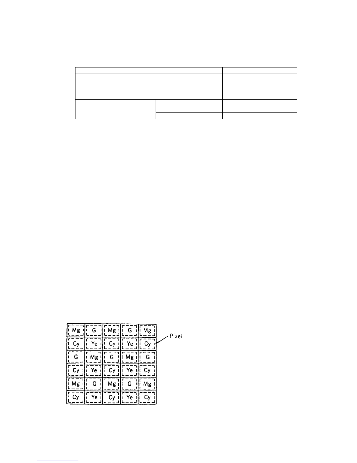
(5) CCD image sensor
CCD, as the nucleus in the camera, converts lens-caught
optical images to TV signals. This device ithe product
of the latest semiconductor technology. Minute pixels
of 400,000(active pixel consists of 752 X 582) or so are
integrated in ultra high density on the small area of
4.8mm(H)X 3.6mm(V) by utilizing sophiscated semi-
conductor technology. As shown in Figure four comple-
mentary color filters of yellow(Ye), cyan(Cy), magenta
(M), and green(G) are placed precisely one on top of
another in a zigzag manner on one picture element so
that color analysis of the subject can be made and
fundemental color signals of red(R), blue(B) and green(G)
are picked out in the color demodulation circuit.
Disposition of color analysis filter on CCD
-14-
Mg: Magneta
G : Green
Cy: Cyan
Ye: Yellow

(6) Smear
When the strong light hits the CCD image sensor, the
image of bands in vertical direction may appear above
and under the spot. This is called smear. Especially if
the camera shoots under the noon sun or its reflections,
a candlelight in the dark, or headlights of cars, this
smears may stand out in the picture.
The CCD used with the CS6100P is designed against the
smear. However, watch out for smear when shooting
involves a strong light sources.
(7) ASC (Automatic Sensitivity Control) and AGC (Automatic
Gain Control)
When a camera is directed toward a subject, the most
proper combination of shutter speed and lens aperture is
automatically determined in accordance with the bright-
ness of the subject. This is the program AE (Automatic
Exposure) mechanism incorporated in an ordinary 35mm
still camera. Meanwhile, just like in a 35mm camera,
the program AE mechanism housed in the video camera
automatically selects the speed of the electronic
shutter depending on the lighting. Simultaneously, the
amplifier gain in the camera instead of the lens
aperture (iris) value is likewise automatically adjusted
according to the pre-selected shutter speed to obtain
the most appropriate video signal level.
(8) Lenses
Generally, there are many kind of lenses for the video
camera on the market, forexample, different aperture
(iris), different focal distance, zoom lenses and so on.
Those having a shorter focal distance are called "wide-
angle" lenses, and those having a longer focal distance
are called "telephoto". Lenses of different focal
distances have specialcharacteristics and you can take
advantage of these in shooting. When the camera is
fitted with a zoom lens,it is extremely easy to vary
the focal distance. Anyhow, make choice of the most
appropriate lens for your application or system.
-15-

6, TROUBLE-SHOOTING GUIDE
What may initially appear to be trouble is not always a
real problem. Make sure first according to the following
table before requesting service.
Symptoms Check points
Power *Is the battery pack
No power correctly installed ?
is supplied *Is the battery pack charged ?
Is the power supply unit
correctly connected ?
*Is the POWER switch of the
connected AC adapter set to ON ?
Picture colors *Have you moved to a
greatly differ different location after
from actual adjusting white balance ?
subject colors. *Or have you shot after 5
hours have elapsed from the last
white balance adjustment?
If so, readjust white balance.
*Have you shot with the
WHITE BALANCE switch set to
"AUTO" under mixed lighting or
a cloudy sky?
If so, adjust white balance.
White balance *Have you aimed the lens at
is not possible. a white object?
*Is the exposure proper?
If not so, increase or
decrease lighting.
Halation or *Check whether the iris ring has
black-out occurs. accidentally moved out of
the normal position.
-16-

7. SPECIFICATIONS
(1) TV system
(2) Image sensor
Active pixel
Active image area
(3) Number of
scanning lines
(4) Scanning system
(5) Sync. system
(6) Scanning frequencies
Horizontal drive
Vertical drive
(7) Aspect ratio
(8) Illumination
Standard
Minimum
PAL
Interline CCD
752 (H) X 582 (V)
4.8mm(H)X3.6mm(V)
(equivalent to 1/3 inch
optical image size)
625 lines
2 : 1 interlace
Internal / External
(automatic change over)
15,625 kHz
50 Hz
4:3
2500 lux at F8, 3000K
10 lux (F1.4, AGC-ON,
output level for 25%)
(9)Video output
PAL VBS 1.0 Vpp/75Ω
Y/C (S terminal) 1.0 Vpp/75Ω
RGB VS 0.286Vpp/75Ω
V (when SYNC OFF) 0.7 Vpp/75Ω
(10)Resolution
Horizontal 460 TV lines
Vertical 420 TV lines
(11)S/N (luminance) 46 dB or more
(12)External sync. Pulses
HD
VD
SYNC
4 Vpp ± 2 Vpp/ high impedance
negative polarity
15.625 kHz 50ppm
4 Vpp ±2 Vpp/ high impedance
negative polarity
50 Hz ±50ppm
2 Vpp ± 1 Vpp/ high impedance
negative polarity
-17-
Table of contents


 owner's manual")


