TopCold Romeo User manual

Romeo
VersionVersion: 1.0: 1.0
For safe and correct use of the equipment, be sure to read the Safety Information in
this manual before using it.
Manual
Manual
MAINTENANCE
COMMANDS
RECYCLING
ANOMALIES
UNPACKING
ASSEMBLY
PROCESURES
OPERATION
BASIC SECURITY PRECAUTIONS

2 31

30
9. Assembly
Procedures
3
THANK YOU
Thank you for purchasing a Frilixa Refrigerator!
This unit has passed our strict Quality Control Inspection and meets the high standards set. You have made
a quality investment that with proper maintenance will give you years of service.
Please read the following installation and maintenance instructions before installing or using your unit. If
you have any questions, please call our Customer Service Department at (+351) 255 490 541.
IMPORTANT INFORMATION - PLEASE READ
Please read these instructions carefully before installing or using. If recommended procedure are not
followed, warranty claims will be denied.
Frilixa reserves the right to change specications and product design without notice. Such revisions do
not entitle the buyer to corresponding changes, improvements, additions or replacements for previous-
ly purchased equipment.
A detailed Owners Manual with a troubleshooting guide, parts lists and additional information can be
ordered from the factory.
The following book is available at our website.
4
Install the unit on a at, clean area away from sources of heat, always in places
where there is fresh water projection;
Plug the appliance into a mains socket with earth contact;
Periodically check the condition of the power cord of the appliance and the wall
socket of your installation. In case they are damaged, call for assistance;
Before starting any maintenance operation and equipment cleaning disconnect
the unit from the mains by removing the plug from the socket;
To make changing bulbs, unplug the appliance by removing the plug from the
socket.
Do not overload the equipment. Please meet the load limit, when applied.
One must not store explosive substances such as aerosols containing ammable
gas propellants;
The models were designed for operation under conditions of bold.
29
Water on oor
Bad leveled.
Evaporation system failed.
If some water appears on the oor, see if the
equipment is leveled.
Check if the automatic system of evaporation
of waters is working properly or drain waters
system is not blocked.
Some condensate waters can be released on
the walls because of bad circulation of steam
so keep the device away from walls.
Controller failed
Probe unwired from the terminals.
Probe with cut wire.
Probe with humidity.
See if there is any message error on the dis-
play.
Check that switches are well connected; if so
call the technician to check for the possible
failure.
Controller “burnt”
Power excess.
Starts exceed.
Water in the circuit.
Replace the controller and check the origin of
the failure.
Controller with unsettled parameters
Operating by unskilled people. Call the technician to reprogram the controller
parameters.
Condenser fans failed
Failure by obstruction. Replace fans.
Check the source of failure.
Evaporator fans failed
Water inside the circuit.
Failure by obstruction.
Replace the fans.
Check the source of failure.
Lights failed
Starter or tube failure
If the tubes don’t light check them or starters.
When you replace the tube and if this is still
failing then replace the ballast.
It may come from the oxidation of the termi-
nals because of the humid ambient of these
devices
.
Condensate water evaporation system
Heater burnt.
According to the system you are using, if your
equipment makes the power supply down or
circuit breaker down, it is possible that one of
the components has ground wired and it may
be the heater burnt.
Note: these operations should be carried out
by skilled people and when heaters are diving
in water.

28
8. Anomalies
GENERAL TROUBLESHOOTING LIST
Failure Possible Reason What to do
The device is not working, does not
start.
No power to unit
Check if plug is properly wired.
Check if plug is ground and neutral
wired.
Check if any circuit breaker is down in
the electrical box.
Not cooling
Condenser blocked.
Evaporators blocked.
Air ow in the condenser obstructed.
It often happens that all the refrigera-
tion components are working and still
don’t cool.
Check :
The condenser – make sure it is clean
otherwise clean it.
Remove all the objects that may pre-
vent the good air ow into the conden-
ser.
The evaporators - check evaporators
for ice or blocked with products that
may prevent the air ow.
If they are blocked press dF button and
wait until the ice is completely re-
moved even if you need to repeat this
operation.
Remove all the objects that may pre-
vent the good airow into the evapora-
tors.
As general advice: avoid direct sunlight
or heat sources that can aect on the
device like heaters, projectors, ventila-
tors or air conditioning equipment and/
or ventilation that has direct eect on
the refrigerated equipment.
Compressor broke down
Compressor “burns” for:
Too many starts.
Lack of refrigerant.
Power supply failure.
Filter obstructed.
Condenser obstructed.
If the compressor is “burnt”, the techni-
cian who will replace it has to consider:
Refrigerant recovery if still existing.
Do not pour the oil of the replaced
compressor.
To be quick in the replacement so that
the oil of the new compressor is not in
contact a too long time with the air as
this later is highly hygroscope (capacity
of absorbing water).
Once the circuit is sealed, make a good
vacuum and recharge the quantity of
refrigerant.
Filters should be also replaced as these
have the property of retaining undesira-
ble particles in the installation and also
humidity.
The compressor should be replaced by
one with identical features.
Refrigerant leaking
Charging valve unscrewed.
Poor use solder.
Incomplete welding.
Broken tubes.
Attempted defrosting with pointed
objects.
Check if the device is working.
If the condenser is not obstructed.
If the condenser is not obstructed and if
the fans are working switch of the de-
vices as it looks like a leak refrigerant.
Call engineer to detect the leak, to elim-
inate it and change the lters – make
the vacuum and replace the refrigerant
quantity.
5
SECURITY
a) The personnel responsible for the moving and instillation of the equipment
must have gloves, which should be exible and anti-sliding, have protective
glasses as well as protecting shoes.
b) Protection equipment must always be used when necessary.
c) In general the best practices for safety in work and hygiene should be applied
when working.
d) To clean, the equipment should always be unplugged.
e) Never use sharp objects when cleaning the equipment.
1. Basic Care Security

6
2. Procedures
PROCEDURES
Verify the general aspect of the package. In the case there are signs of bad handling
during transport, referrer this in the transport documentation and inform your sup-
plier. If all is well please proceed as follow:
1. The location where the cabinet will be installed is very important for its good
working and consequent energy saving.
Avoid the proximity of heating sources (heaters, stoves, condensers and other appli-
ances, etc.) drafts (windows, doors, ventilation systems, air conditioning, etc.), and
places with strong exposure to solar rays.
Make sure that the socket of the feeding cable is always accessible.
Remove carefully plastics that protect some components.
Note: this equipment has not been developed to work in open air neither under
rain.
2. In case that this manual has also additional “Assembling instructions”, please
follow the order mentioned for correct installation.
3. We recommend that when necessary an adequate mechanical protection is
made, to avoid possible damages to the equipment caused by moving objects such
as trolleys, cleaning machines, forklifts and other equipment.
4. Clean the interior and exterior of the cabinet with a smooth cloth and warm wa-
ter with neutral soap (5% of the water volume).
Avoid that is gets splashed by the cleaning products used to wash the establish-
ment. The substances used in cleaning of the oors can attack chemically the com-
ponents of the unit.
Dry carefully all the rests of water with the help of a sponge. On the glass parts / acryl-
ics use appropriated liquid to clean them.
27
7. Recycling
ENVIROMENTAL PROCTECTION
This equipment does not contain CFC’s. Neither inammable gases.
Unpacking
All packing materials are recyclable and should be eliminated according to local regulations. Plastic
bags must be kept away from children in order to avoid potential hazard.
End of life cycle
When the product reaches the end of its life cycle, we recommend to:
1. Make it unusable (ex. by cutting the power supply cable);
2. Remove the doors and other element, which eventually could be harmful to children.
3. In the case of complete dismantling, we recommend to strictly respect the local regulations re-
garding waste disposal.
V

26
CONTROL LOCATIONS
Thermostat
Switch:
A: Light
B: Main 220V
7
When ever a spillages or contamination happens as a consequence of the rupture of a package
inside the unit, it should be cleaned immediately and the evaporation tray of the condensed
water should be drained right away. Verify that the pipes of the sewer are not obstructed.
5. Level the cabinet on the horizontal, by adjusting the feet to aloe:
Its good functioning,
A perfect disposal of residual waters and defrost waters of evaporator,
Noise reduction caused by the vibration of the moving parts.
6. The condensation group (compressor + condenser), commonly installed on the bottom of the
cabinet, should not have, around it, any obstacle that reduces the necessary free circulation of air.
Therefore, near the air circulation zones, you should not put boxes or other objects.
7. Verify it the power supply voltage and the tension of the place where the cabinet will be installed
is according to what is indicated on the identication plate.
The connection must have a ground wire element that, besides being necessary, is demanded by law.
The appliance is not equipped with electric protection devices against overload, so it is recommend to
verify the electric safety level of the installation network where the cabinet will be installed.
Do not connect any other appliance to the same power socket, nor use socket extensions.
We decline all liability for eventual injuries that may result to people, animals or products (good) for not
respecting these instructions.
8. Turn on the cabinet 1 (one ) hour after it has been installed.
On the appliances equipped with electronic thermostat temperature regulation is made according to
the specic instructions that are supplied with the cabinet. This thermostat is already programmed
from factory,; any changes made should be done by specialized technicians.
9. The control lights, in the case they exist, show the operation mode of the appliance:
WHITE Switch light () with the light ON > means that the light of the unit it turned on.

8
GREEN Control On > means that the compressor is working.
10. After the cabinet has been switched on wait, at least 2 (two) hours before lling it with products.
Make sure that lling the cabinet with the goods, the air circuit is not obstructed. (Example: the grids
of air discharge and air intake, “Suction” and “Insuation”)
11. Respect the loading limits that are mentioned either directly on the cabinet by “______
___” or by the sticker aside the label with the features of the cabinet. Never display, products above
this refrigeration level, as it can create disturbances of the air ow and as a consequence deteriorate
the food products displayed.
The shelves (in case they exist) placed above the refrigeration level they are exclusively to display
products that are not in need of refrigeration (excluding the models that are conceived for such).
We remind that this equipment has not been conceived to lower the temperature of the food
products displayed, but to maintain the temperature of the food products there placed.
Food products with temperature above the one recommend for the working of the equipment must
not be placed inside the unit.
Do not leave the food products in boxes or pallets more than the necessary time to load the equip-
ment (unit).
In the food display equipment; food products must be removed during the night and placed in a Cold
Room or similar equipment to preserve the food temperature during the night.
In order to optimize the working of the equipment and the conservation of the food products use only
complements and accessories supplied with the unit.
When the equipment is supplied with manual night curtains (that normally is an option), they must be
opened and closed carefully in order to avoid the losing the vertical aliment and start to deteriorate.
Night curtains should always be used in order to reduce energy consumption.
When closing the night curtain do not forget to turn of the light inside the equipment.
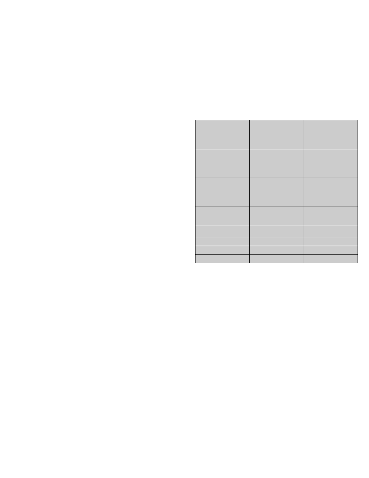
25
Table of EZY parameter sets
TroubleshooƟng
The following table shows a number of anomalous situaons that may occur on the various models. The most frequent causes and corre-
sponding checks are described:

24
Table of easy compact parameters
9
3. Operation
INSTALLATION OF THE SHELVES
All of the equipment are provided with shelves with pilasters and the shelf supports clip.
The shelves are easily installed over the on the pilasters support clips that t easily.
Align the shelves just as the smaller wires from front to back ll and place the shelf over the clips. (See
the Service Manual)
ELECTRICAL PREVENTION
Wiring should be performed by a qualied electrician in accordance with local electrical codes.
Ground wire separately shall be provided for all installations.
The properly connected equipment goes ensure proper operation.
Requirements for electrical feeding equipment are in the serial / data plaque. (See Fig1)
Fig1
Subtitles:
Recommended is a hotline., properly protected size appropriate from the facility's main source of
equipment
To ensure the correct voltage to be supplied, while the equipment this one in operation get a
voltage reading with the engine-compressor electric connections.
1. Serial Number
2. Model
3. Voltage / Frequency ( V/
Hz)
4. Power (W)
5. Current (A)
6. Refrigerant
7. Quantity Gas
8. IP - Protection
9. Electrical Resistance (W)
10. Illumination (W)
11. Climatic class

10
INSTALLATION CHECKLIST
After the cabinet has been installed, leveled and cleaned as described, refer to the following checklist prior to start-up.
Check for proper electrical hook-up
Check exposed refrigeration line connections for leaks. Make sure refrigeration lines are not dented, kinked or rub-
bing.
Check condenser fan for freedom to rotate without striking any stationary members.
Check that cabinet is level.
PRODUCT LOAD
After the refrigerator has been started and reaches the proper storage temperatures, food may be loaded. For opti-
mum energy eciency, we recommend allowing a 1-1/2’’ clearance between the interior cabinet wall and product
load.
Important Notices
Do not spill water on the equipment or on electrical components.
Do not use pressure water (jet) or any type of metallic objects in order to remove impurities or dirt.
Do not use substances or materials that are abrasive or solvents, avoiding the use of muriatic acid as well as chlorine-
based detergent or pure alcohol.
!
23
reconnect power while holding the SET and DOWN buttons;
the display will show the message “CF”;
after a few seconds the instrument starts operating with the default conguration. Any dierent parameter set-
tings will need to be updated.
22
Modifying the parameters
Parameter navigation
The operating parameters, modiable using the keypad, are divided into two types: frequent (type F) and congura-
tion (type C). Access to the latter is protected by password (default= 22) to prevent accidental or unauthorized modi-
cations.
Accessing the type F parameters:
press the SET button for more than 3 s (if there are active alarms, mute the buzzer), the display shows the parame-
ter code ‘PS’ (password);
use the UP and DOWN buttons to scroll the parameters. The LED corresponding to the category of parameters
will be on (see Table 5.b);
press SET to display the value associated with the parameter increase or decrease the value using the UP or
DOWN button respectively;
press SET to temporarily save the new value and display the parameter again;
repeat the procedure for any other parameters that need to be modied;
press the SET button for more than 3 s to permanently save the parameters and exit the parameter setting proce-
dure.
Accessing the type C parameters:
press the SET button for more than 3 s (if there are active alarms, mute the buzzer), the display shows the parame-
ter code “PS” (password);
press the SET button to access the password setting;
use the UP and DOWN buttons to scroll the numbers until displaying “22” (password to access the parameters);
press the SET button to conrm the password;
use the UP and DOWN buttons to scroll the parameters. The LED corresponding to the category of parameters
will be on (see Table 5.b);
press SET to display the value associated with the parameter increase or decrease the value using the UP or
DOWN button respectively;
press SET to temporarily save the new value and display the parameter again;
repeat the procedure for any other parameters that need to be modied;
press the SET button for more than 3 s to permanently save the parameters and exit the parameter setting proce-
dure.
Setting the default parameters
To reset the default parameters:
disconnect power from the instrument;
11
4. Unpacking
RECEPTION OF THE MATERIAL
Proper installation is the rst step to operation. We recommend that your refrigerator be in-
stalled by authorized Frilixa Certied Installer.
All units are performance tested and thoroughly inspected prior to shipment. Upon leaving the fac-
tory, all units are in perfect condition. Upon receipt, examine the exterior of the shipment packaging
for any signs of rough handling. If the cabinet is damaged, it should be note on the delivery slip or bill
of lading and signed. A claim must be lled immediately against the carrier indicating the extent and
estimated cost of damage incurred.
UNPACKING
Tools Needed: Crowbar
Level
WARNING: Never lay your refrigerator down on either its back, front or sides. This allows compressor
oil into the refrigerant lines which can damage the compressor at start-up. If the unit is laid down, it
must be set upright for a minimum of 12 hours before starting the compressor. Failure to adhere to
the above recommendation will void the warranty.
1. Split plastic wrap along one of the cardboard posts. Remove and discard all packaging material,
tape and interior components.
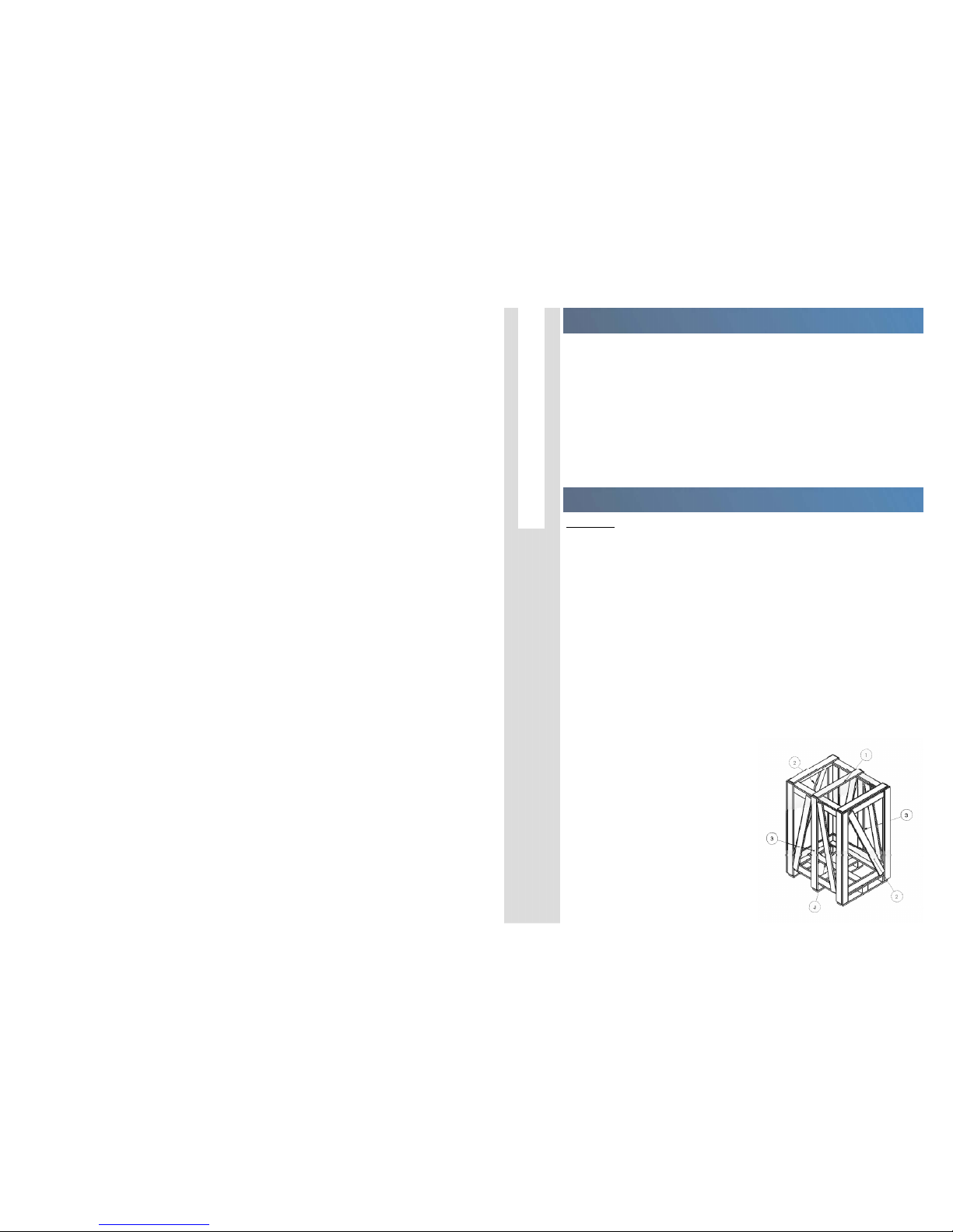
2. Move cabinet as close to nal location as possible before removing skid.
3. Remove the shipping skid by tipping the cabinet forward. Remove the nails of carriage with a
crowbar in the following order:
1) Top Side;
2) Part Sides;
3) Part Front / Back;
4) Background.

12
5. Maintenance
1. Remove panel on the front side by lifting it up with a screwdriver.
2. Slide the side panels backwards and remove these panels.
3. Loosen the screws from the back panel and lift this panel out.
4. Reverse the procedure to install.
INSTALLING SHELVES
1. For removing the shelves is only neces-
sary to push forward.
2. Reverse the procedure to install.
PANELS BOTTOM SIDE
21
check parameters AH, Ad and A0.
The alarm is automatically reset when the temperature returns within the set limits (see parameter AH).
EE displayed during operation or on power-up
unit parameter reading error. See Data errors.
EF displayed during operation or on power-up
operating parameter reading error. See Data errors.
Ed ashing
The last defrost ended after exceeding the maximum duration rather than when reaching the end defrost set
point.
check parameters dt, dP and d4;
check the eciency of the defrost.
The message disappears when the next defrost ends correctly.
dF ashing
defrost running:
this is not an alarm signal, but rather a message that the instrument is running a defrost. Only shown if
d6= 0.
cht ashing
dirty condenser pre-alarm:
check parameters A4, Ac, AE and Acd.
CHt ashing
dirty condenser alarm:
check parameters A4, Ac, AE and Acd.
EtC ashing
internal clock error.
Data error
In certain operating conditions, the instrument may detect errors in the data saved. These errors may compromise the
correct operation of the instrument. If the microprocessor detects a data saving error, the display shows the message
“EE”. If the fault persists, the controller needs to be replaced. If, on the other hand, the message disappears, it can con-
tinue to be used. When “EE” error occurs frequently and/or remains for some time, the controller should be checked,
as the original precision may not be guaranteed.

20
The activation of the corresponding function is delayed by a timer, awaiting an external signal or disabled by
another procedure that is already in progress. e.g. if is a continuous cycle in progress and a defrost is called,
the latter will remain pending until the end of the continuous cycle, and the corresponding LED (defrost) will
ash.
E0 steady or ashing
control probe error:
probe not working: the probe signal is interrupted or short-circuited;
probe not compatible with the instrument;
The alarm signal E0 is steady if it is the only active alarm (the temperature value is not displayed), while it
ashes if other alarms are active or the second probe is displayed.
E1 ashing
evaporator probe or food conservation probe error:
probe not working, the probe signal is interrupted or short-circuited;
probe not compatible with the instrument;
E2 ashing
condenser probe or food conservation probe error:
probe not working, the probe signal is interrupted or short-circuited;
probe not compatible with the instrument;
IA ashing
immediate or delayed alarm from multifunction digital input:
check the multifunction input and parameters A4 and A7.
dOr ashing
open door alarm:
check the multifunction input and parameters A4 and A7.
LO ashing
low temperature alarm. The probe has measured a temperature lower than the set point by a value that ex-
ceeds parameter AL:
check parameters AL, Ad and A0.
The alarm is automatically reset when the temperature returns within the set limits (see parameter AL).
HI ashing
high temperature alarm. The probe has measured a temperature higher than the set point by a value that
exceeds parameter AH.
13
PERIODICAL MAINTENANCE
1. The appliance, when equipped with automatic defrosting programmer, should be switched o
and cleaned (see “Cleaning” chapter) at least once a month. The accumulation of ice in the evapora-
tor reduces the performance and makes the energy costs rise. Never remove the ice from the
evaporator with metal objects such as knifes or cutting objects. When the evaporator has ice
the ideal is to let it defrost naturally of the evaporator.
Water resulting from daily defrosting is collected in a plastic recipient that must be emptied, whenever
necessary. In some models this procedure is not necessary since the water is re-evaporated in an ap-
propriate place. Special attention must be taken when a defrosting is made after ice is created in
the evaporator, as the recipient for the condensed water may not have sucient capacity and
overow.
2. Before any maintenance or cleaning operation the appliance must be unplugged in order to guar-
antee, that it is not connected to electric power. The plug must be removed from the socket in order
to insure that there is no electrical current of any type. Then remove all the products that are inside the
cabinet and place them in a cold room or an adequate conservation place.
Whenever necessary to remove any protection or isolation all the procedures for this must be correctly
followed. Never restart functioning without making sure that all the removed elements have been dul-
ly tted on the appliance.
CLEANING
Internal and external cleaning must be done periodically with a soft cloth and warm water with neutral soap (5% of
the water volume) without chlorine.
In this chapter it is very important that the drainage hole of the condensed water is perfectly clear.
“Dry carefully all the rests of water with the help of a sponge.”
On the glass parts use appropriated liquid to clean them.
Condenser cleaning should be made periodically or, whenever it shows impurities or lth that may hinder or block
free circulation of air.
The removal of impurities or lth must be done using a brush of soft hair (never use a metal brush), a vacuum cleaner
or with air pressure ow. (View Fig2/3)

14
1. Remove panel on the front side by lifting it
up with a screwdriver.
2. Cleaning the condenser as in the picture
3. Reverse the procedure to install.
Fig2/3
19
Continuous cycle
Not available on the easy and easy compact thermometer models (M).
Press UP+DOWN for more than 3 s (activated only if the temperature conditions are right).
The continuous cycle is used to maintain refrigeration active in the cabinet or cold room, regardless of the tempera-
ture inside the unit. This may be useful for rapidly bringing the temperature below the set point value.
Rapid display of the temperature read by the other probes
Press the DOWN button to scroll the temperatures read by the probes.
Each time the DOWN button is pressed, the display will show the name of the probe Pr1, Pr2 or Pr3 (only on the mod-
els with 3 inputs and with multifunction input congured as a probe) and after 1 s the temperature measured by the
selected probe will be displayed.
To display the other probes, press DOWN again.
To return to the normal display, wait 3 s without pressing any buttons (exit by timeout).
TABLES OF ALARMS AND PARAMETERS
Table of alarms and signals
When an alarm is activated, the display shows the corresponding message that ashes alternating with the tempera-
ture; if tted and enabled, the buzzer and the alarm relay are also activated. All the alarms have automatic reset (that
is, they stop when the causes are no longer present), except for alarm ‘CHt’ which has manual reset (instrument on/
o using the UP button or by disconnecting the power supply). Pressing the SET button mutes the buzzer, while the
code displayed and the alarm relay only go o when the causes of the alarm have been resolved. The alarm codes are
shown in the table below:
Description of the main signals and alarms
LED ashing

18
On and o
Switching the instrument ON: press UP for more than 3 s (when pressing the button, the display shows ON).
Switching the instrument OFF: press UP for more than 3 s. The display shows the message “OFF”, alternating with the
temperature measured by the set probe.
In o status, the following functions are disabled (if featured by the model):
compressor control / duty setting / continuous cycle;
defrost;
fan control;
alarms : ‘LO’, ‘HI’, ‘IA’, ‘cht’, ‘CHT’;
door switch (A4= 7/8 );
buzzer (when available)
While the following are enabled:
temperature display, alternating with the message “OFF”;
parameter display and setting;
alarms: “E0”, “E1”, “E2”;
the internal timer relating to parameter ‘dI’ is updated. If ‘dI’ expires in
OFF status, a defrost is performed when restarting;
auxiliary relay management, only in the following congurations:
H1= = 1/2 (“E0” alarm only)
H1= 3, A4= 6;
Set point setting (desired temperature value)
The easy and easy compact devices control the desired temperature (set point) inside the cabinet or cold room di-
rectly and dynamically.
To view and modify the set point:
press SET for 1 s, the set value will start ashing;
increase or decrease the value using UP or DOWN;
press SET to conrm the new value.
Important: the PJEZM* models tted with keypad simply monitor the deviation from the set point and where neces-
sary signal na alarm. On these models, the set point can only be modied using parameter “St”.
Manual defrost
Not available on the easy and easy compact thermometer models (M).
Press DOWN for more than 3 s (activated only if the temperature conditions are right.
15
6. Commands
ADJUSTING CAREL PJEZ
INTRODUCTION
Easy and easy compact are electronic microprocessor controllers with LED display, developed for the management of refriger-
ang units, display cabinets and showcases. They exploit the experience and the success of the previous PJ32 range, with the
objecve of offering a product that is simpler and more economical.
The structure of the parameters has been enhanced with new funcons for more dynamic and effecve management of the
temperature control and defrost. easy compact the smallest, most economical easy model, with one relay only, and a simplified
display.
Main characterisƟcs
The following table lists the main features of the easy and easy compact controllers.
USER INTERFACE AND START UP

16
Display
Keypads
17
Preliminary congurations
Once the electrical connections have been completed, simply power-up the controller to make it operative. CAREL
then recommends to check that the display does not show any alarm signals, then set the time and date, and nally
set the parameters as desired. The main parameters are as follows:
* SC1 - PROBE
** PS - PASSWORD
Functions available from the keypad
Table of contents
Other TopCold Refrigerator manuals


Popular Refrigerator manuals by other brands

Kenmore
Kenmore 2318590 Use & care guide

BOMANN
BOMANN VS 2195 instruction manual

White-Westinghouse
White-Westinghouse WWSS2601KW3 Use & care manual

Sanyo
Sanyo SRA2480 - Commercial Solutions Freezerless Compact... Energy guide

arcelik
arcelik 270560EDI user manual

Electrolux
Electrolux EUF 2330 Installation and instruction manual


Delfield
Delfield Refrigerators and Freezers Service and installation manual

Smeg
Smeg U8L080DF Installation instruction

Kenmore
Kenmore 7531 - 22.0 cu. Ft. Top Freezer Refrigerator Use & care guide

Beko
Beko TLG 980 operating instructions

Electrolux
Electrolux ER 6529 T Instructions for use

Randell
Randell RANFG SCA-2 Specifications