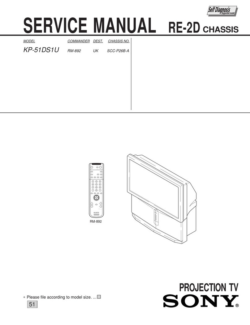
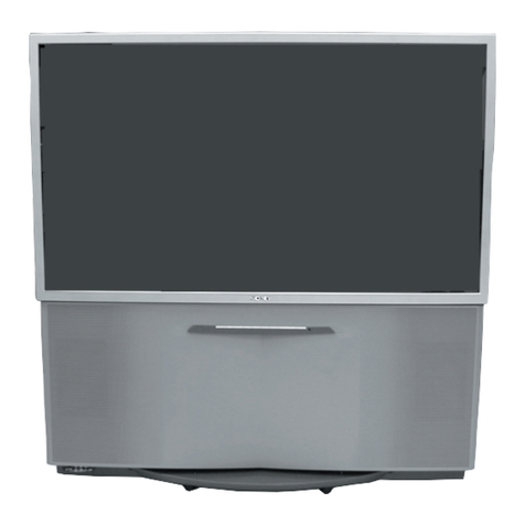
Toshiba TW40F80 User manual
Other Toshiba Projection TV manuals

Toshiba
Toshiba 52HMX84 - Cinema Series HD User manual

Toshiba
Toshiba TZ43V61 User manual
Toshiba
Toshiba CF27G50 User manual
Toshiba
Toshiba TheaterWide 46H83 User manual
Toshiba
Toshiba TW56F80 User manual
Toshiba
Toshiba ColorStream TP43H60 Manual
Toshiba
Toshiba 65H84 User manual

Toshiba
Toshiba TheaterWide 57HX94 User manual
Toshiba
Toshiba 56HM16 User manual

Toshiba
Toshiba 65HC15 User manual

Toshiba
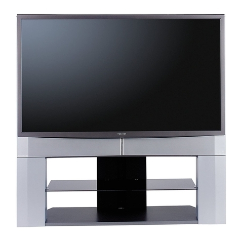
Toshiba TV-GEN-03 Installation guide
Toshiba
Toshiba 62HM196 User manual

Toshiba
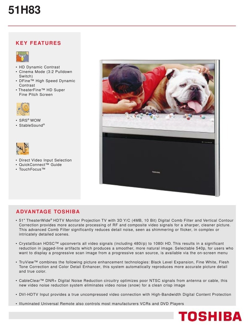
Toshiba TheaterWide 44HM85 User manual
Toshiba
Toshiba TheaterWide 51H83 User manual

Toshiba
Toshiba TheaterWide 44NHM84 User manual

Toshiba
Toshiba TheaterWide 46H83 User manual
Toshiba
Toshiba TN50X81 User manual
Toshiba
Toshiba TN50V71 User manual

Toshiba
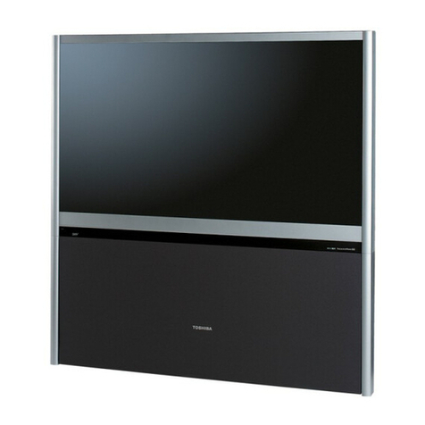
Toshiba 40H80 User manual
Toshiba
Toshiba TheaterWide 51H94 User manual
Popular Projection TV manuals by other brands
Samsung
Samsung ST-43T6P Owner's instructions

Mitsubishi Electric
Mitsubishi Electric WD-65734 Specification sheet
Optoma
Optoma EP652A user manual
Samsung
Samsung SP43T8HPX/XEC Service manual

Philips
Philips 28PW6006 - annexe 1 Eco profile
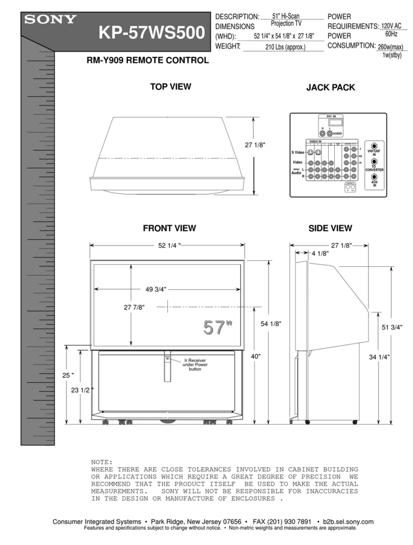
Sony
Sony KP-57WS500 - 57" Hi-scan 1080i™ 16:9 Projection... Dimensions
