Trident Air Force User manual

Air Force
High Speed Air
Handpiece
Instruction
Manual

2
Table of Contents
Introduction…………………………………………………… Page 3
Upon Receiving your Air Force……………………………... Page 4
Installation…………………………………………………….. Page 4 - 5
Maintenance………………………………………………….. Page 5
Warranty……………………………………………………… Page 5
Technical Information………………………………………… Page 5
Accessories & Spare Parts……………………………………. Page 5
Chuck Replacement Instructions……………………………… Page 6
Air Force Schematic…………………………………….….. Page 7

3
INTRODUCTION
Trident Sales Associates thanks you and congratulates you for choosing the
Air Force as your new High Speed Air Handpiece. The Air Force was
designed and engineered by highly qualified personnel with many years of
experience and expertise in handpiece manufacturing. Its construction
underlines the high standards of quality that have always distinguished our
products.
Special “unique” features of the Air Force include:
* High-speed, low-noise zirconia bearings
* An adjustable, easily replaceable chuck system
* An ergonomic comfort grip
* 300,000 rpm of power
This instruction manual will help familiarize you with the Air Force. Please
read it carefully. Keep the manual in a safe place so that it can be consulted
whenever necessary. Should you have any questions please contact:
Trident Sales Associates
195 Basik Drive, Suite 506
Naples, FL 34114
Tel: 561-826-9331
Fax: 561-353-0895
Email: walter@tridentsales.us

4
UPON RECEIVING YOUR AIR FORCE
Carefully inspect the unit to insure that it has not been damaged in shipping.
In the event of any damage, immediately contact the shipping company to
report it.
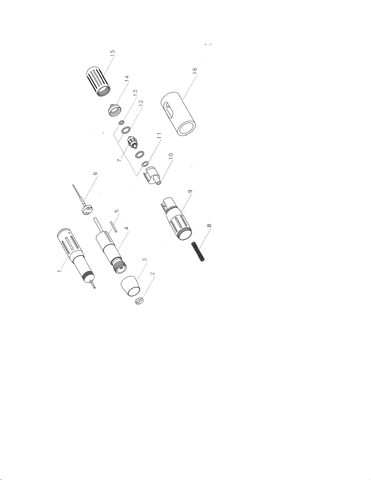
The Air Force comes with the following:
* Air Force handpiece
* Control Box
* Foot Pedal
* Barbed Hose Connector
* Bur Insertion Tool (BIT)
* Warranty Card
* Instruction Manual
INSTALLATION
Remove all items from the shipping box.
Place the Control Box on the bench in the area where it will be used.
Connect the handpiece to the round connector on the hose attached to the
Control Box. Secure this connection in place by tightening the locking ring.
Insert the smaller end of the plastic barbed fitting into the hose that is
attached to the foot pedal assembly. Attach the larger end of the barbed
fitting into your air compressor hose.
Air Pressure Setting: Adjust the pressure regulator located at the top of the
control box to 35 psi MAX (2.5 bar). Do Not use the Air Force above
35 psi (2.5 bar) or you will damage the turbine cartridge.
FG Bur Insertion: Use the Bur Insertion Tool (BIT) to correctly insert the
bur into the chuck. Place the bur into the chuck; place the BIT over the bur
and firmly press straight down. The bur is now properly in place.

5
FG Bur Removal: Firmly hold the center of the handpiece with one hand
and push the rear of the handpiece forward with your other hand. This will
activate the bur ejection mechanism and allow the bur to be easily removed.
MAINTENANCE
The Air Force is equipped with high-speed, zirconia bearings. DO NOT
LUBRICATE THESE BEARINGS.
Periodically check the air ducts at the rear of the Handpiece. Air should
always exit from them. Remove any material that may be obstructing these
ducts.
WARRANTY
The Air Force is warranted for a full year from date of purchase. If the serial
number label is removed, the warranty becomes null and void.
TECHNICAL INFORMATION
Speed…………………………………..…300,000rpm
Recommended Air Pressure (max)………35 psi (2.5 bar)
Handpiece weight………………………..2 oz.
Bur Type…………………………………Straight FG
Bur Diameter…………………………….1.59 – 1.60 mm
Bur Length……………………………….25 mm
ACCESSORIES & SPARE PARTS
Turbine Cartridge……p/n AFTC
Chuck………………..p/n COAF

6

7
Table of contents
Popular Airbrush manuals by other brands

Kärcher
Kärcher WBS 3 manual

Airbrush Heaven
Airbrush Heaven BD-512 user guide

Grex
Grex TRITIUM Series owner's manual

Fast Mover
Fast Mover FMT18-2 Product information guide

Parkside
Parkside PABK 60 B3 Operation and safety notes translation of the original instructions

Profi-AirBrush
Profi-AirBrush Carry IV operating instructions