TriPoint PRODELIN 1892 Series User manual

4096-629
January 30, 2002
ASSEMBLY MANUAL
Revision C
.89/.98M Ku-BAND Rx/Tx
SERIES 1892/1982
ANTENNA SYSTEM
PRODELIN CORPORATION
1500 Prodelin Drive
Newton NC 28658

.98M Ku-BAND Rx/Tx
SERIES 1982 ANTENNA SYSTEM
C Add .89M text 1/30/02
B Revised Diagrams and Text 1/25/02 JL
ARevised Address 1/9/02 RAH
- ORIGINAL RELEASE 3/8/01 CLT
REV. DESCRIPTION DATE APPROVED

4096-629
PRODELIN CORPORATION .89/.98M Ku-BAND Rx/Tx SERIES 1892/1982
2

4096-629
PRODELIN CORPORATION .89/.98M Ku-BAND Rx/Tx SERIES 1892/1982
3
TABLE OF CONTENTS
SECTION TITLE
I INTRODUCTION
1.0 GENERAL INFORMATION
1.1 UNPACKING & INSPECTION
1.2 FREIGHT DAMAGE
1.3 MATERIAL MISSING OR DAMAGED
1.4 MECHANICAL INSTALLATION TOOLS
1.5 FOUNDATION INTERFACE
II ANTENNA SYSTEM ASSEMBLY
2.0 REFLECTOR & SUPPORT ASM PART LIST
2.1 ANTENNA ASSEMBLY
2.2 FEED SUPPORT PART LIST
2.3 FEED SUPPORT ASSEMBLY
III SATELLITE ALIGNMENT
3.0 ANTENNA POINTING
IV MAINTENANCE
4.0 MAINTENANCE OVERVIEW
4.1 REFLECTOR
4.2 MOUNT & REFLECTOR SUPPORT
4.3 FEED & FEED SUPPORT

4096-629
PRODELIN CORPORATION .89/.98M Ku-BAND Rx/Tx SERIES 1892/1982
4
SECTION I INTRODUCTION
1.0 GENERAL INFORMATION
This manual describes the assembly and installation of Prodelin's .89/.98 meter
antenna systems. The Prodelin .89/.98 meter is a rugged and reliable mount
which will operate in the Ku-Band frequency with high efficiency and at the same
time successfully withstand the effects of the environment. Prodelin’s .89/.98
Meter antennas have an F/D ratio of .8, an offset angle of 16°, and is commonly
used with a 39° Prodelin Feed Horn.
These instructions are listed by sections that cover all areas of assembly and
installation. Additional sections are included in the manual to provide information
on antenna alignment to the satellite and maintenance.
1.1 UNPACKING AND INSPECTION
The system containers should be unpacked and inspected at the earliest date to
insure that all material has been received and is in good condition. A complete
packing list for each major component is supplied.
1.2 FREIGHT DAMAGE
Any damage to materials while in transit should be immediately directed to the
freight carrier. He will instruct you on matters regarding any freight damage
claims.
1.3 MATERIAL – MISSING OR DAMAGED
Any questions regarding missing or damaged materials that are not due to the
freight carrier should be directed to Prodelin's Customer Service Department at:
PRODELIN CORPORATION
1500 Prodelin Drive
Newton NC 28658
USA
(828) 464-4141

4096-629
PRODELIN CORPORATION .89/.98M Ku-BAND Rx/Tx SERIES 1892/1982
5
1.4 MECHANICAL INSTALLATION TOOLS
The hardware supplied with this antenna system is U.S. SAE standard size.
However, the sizes have been chosen to allow use with compatibly sized metric
wrenches as shown in the table below.
HARDWARE SIZE SAE WRENCH SIZE METRIC WRENCH
SIZE
MAXIMUM REC.
TORQUE
5/16” Bolt 1/2” 13 mm 12 ft-lbs
(16.27 n-m)
1/4” Bolt 7/16” 11 mm 6 ft-lb
(8.14 n-m)
3/8” Bolt 9/16” 15 mm 22 ft-lbs
(29.83 n-m)
1/2” Bolt 3/4” 19 mm 45 ft-lbs
(61.02 n-m)
Also recommended for installation:
Compass - graduated to .5°
Adjustable Wrench
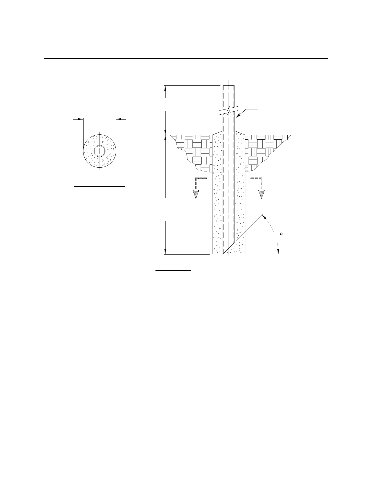
1.5 FOUNDATION INTERFACE
The required interface from the foundation to the mount is 2-1/2" schedule 40
pipe (2.88" O.D.). A suggested in-ground foundation is shown in Figure 1.
Also available from Prodelin, as options, are a kingpost pedestal mount and
a non penetrating mast mount.
4096-629
PRODELIN CORPORATION .89/.98M Ku-BAND Rx/Tx SERIES 1892/1982
6
SUGGESTED IN-GROUND FOUNDATION
18.0
(
MIN
)
45
A
2 1/2” SCH 40 PIPE
(2.88 O.D.)
12.0
SECTION A - A
A
30.0
SEE NOTE #7
FIGURE 1.
NOTES:
1. 2 1/2” schedule 40 pipe should conform with ASTM A53.
2. All concrete should conform to building code standards and have a
minimum compressive strength of 3000 PSI at 28 days. (Per ACI-318-77)
3. Soil bearing capacity should be no less than 2000 PSF.
4. Concrete should be poured against undisturbed soil.
5. Allow concrete 24 hours set time before installation of antenna.
6. The antenna should be properly grounded to meet applicable local codes.
7. Minimum depth as shown or extend to local frost line.
8. Foundation meets the design requirements as set forth by the uniform building code.
(1982 edition)
(PRODELIN CORPORATION DOES NOT REPRESENT OR WARRANT THAT ANY PARTICULAR
DESIGN OR SIZE OF FOUNDATION IS APPROPRIATE FOR ANY LOCALITY OR EARTH STATION
INSTALLATION.)

4096-629
PRODELIN CORPORATION .89/.98M Ku-BAND Rx/Tx SERIES 1892/1982
7
SECTION II REFLECTOR AND SUPPORT ASSEMBLY
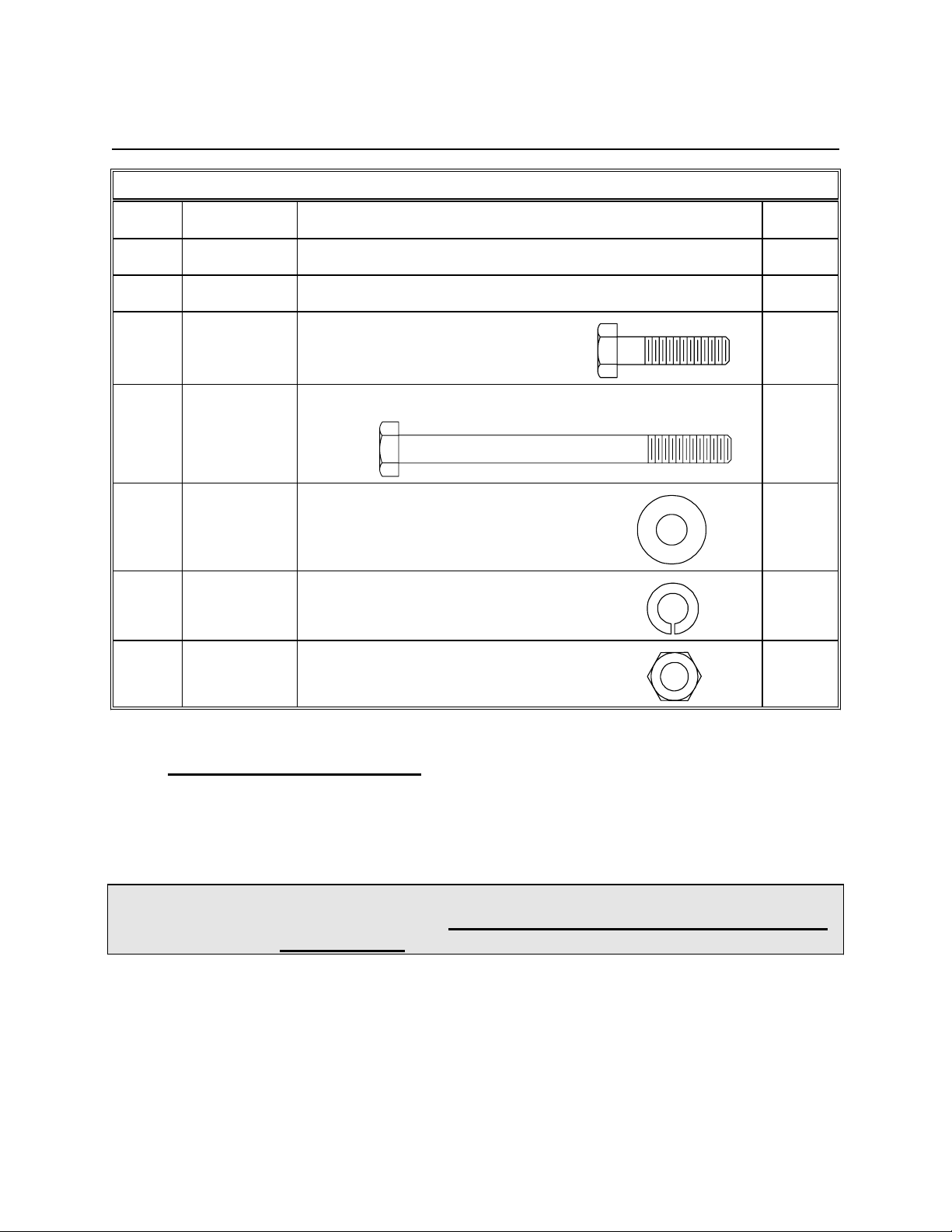
REFLECTOR AND SUPPORT ASSEMBLY PART LIST- TABLE 2.0
ITEM PART NO. DESCRIPTION QTY
1 VARIES .89/.98M Reflector 1
2 0185-171 Az/El Positioner Assembly 1
3 0158-093 Interface Plate 1
4 8038-012 2
5 8038-024 2
6 8032-008 4
7 8201-042 8
8 8202-042 4
9 8102-007 4
5/16” x 2.00 Carriage Bolt
5/16” x 3.00 Carriage Bolt
3/8” x 1.00 Hex Bolt
3/8” Flatwasher
3/8” Lockwasher
REFLECTOR AND SUPPORT ASSEMBLY PART LIST- TABLE 2.0
3/8” Hex Nut
4096-629
PRODELIN CORPORATION .89/.98M Ku-BAND Rx/Tx SERIES 1892/1982
8
QTYITEM DESCRIPTIONPART NO.
10 8201-041 4
11 8202-041 4
12 8101-009 4
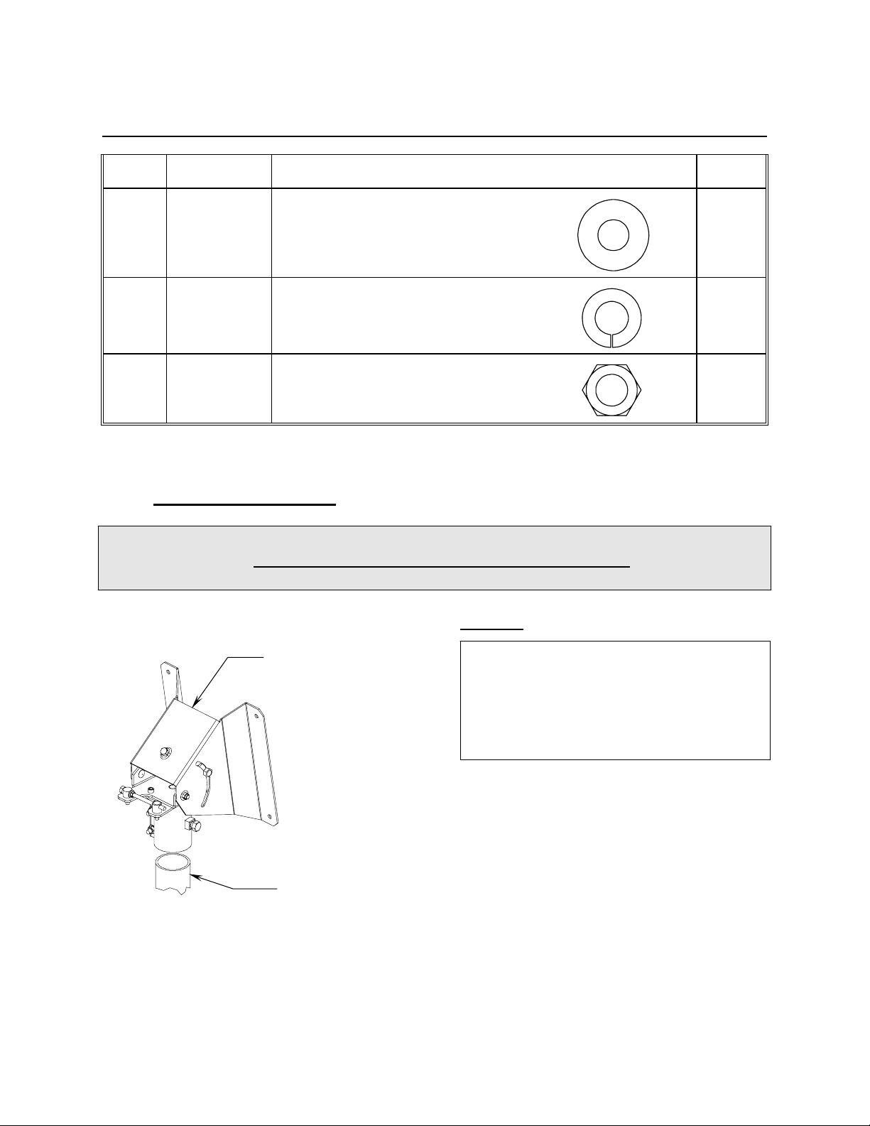
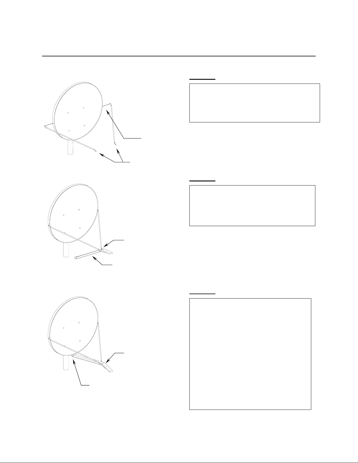
.1 ANTENNA ASSEMBLY2
CAUTION: During the assembly procedure, the sequence of instructions must
be followed. Do Not Tighten Any Hardware Until Instructed.
Refer to the parts list table and the referenced steps.
STEP 1.
Slip the Az/El Positioner (item 2) onto
the mast pipe as shown. Point Az/El in
general direction of satellite azimuth
heading and tighten the canister bolts
at this time.
Mast Pipe
Az/El
Positioner
5/16” Hex Nut
5/16” Flatwasher
5/16” Lockwasher
4096-629
PRODELIN CORPORATION .89/.98M Ku-BAND Rx/Tx SERIES 1892/1982
9
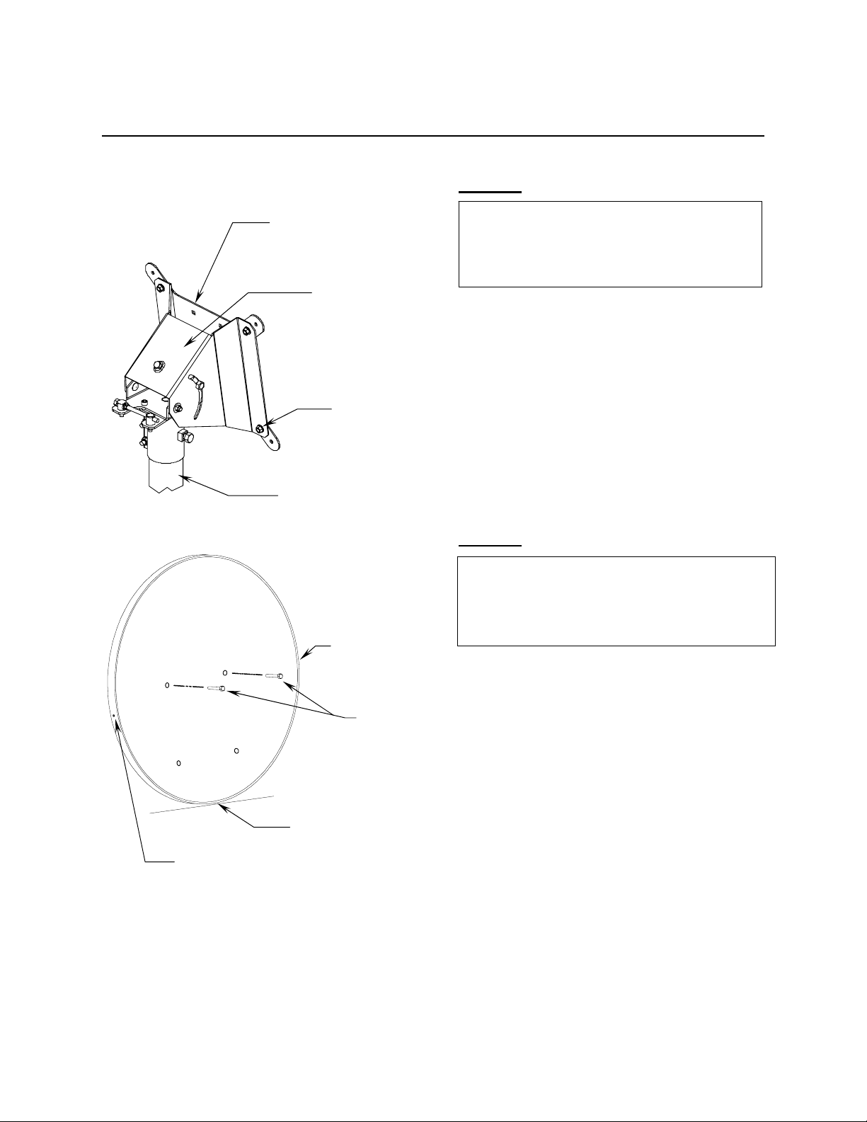
STEP 2.
Attach Interface Plate (item 3) to the
az/el positioner using the 3/8”
hardware provided (items 6,7,8,9) as
shown. Tighten completely.
Az/El
Positione
r
[ 3]
[ 6,7,8,9 ]
Typ 4 Places
Mast Pi
p
e
STEP 3.
Stand the reflector on its bottom edge
and insert two 5/16”x 2.00” carriage
bolts (item 4) thru the top two holes as
shown.
Hole for
Feed Rod
[ 4 ]
Hole for
F
eed
R
od
Hole for
Feed Support
4096-629
PRODELIN CORPORATION .89/.98M Ku-BAND Rx/Tx SERIES 1892/1982
10
STEP 4.
[ 4 ]
[ 10,11,12
]
Hole for Feed Support
[ 10,11,12 ]
[ 5 ]
A) With the top two bolts in place, lift
the reflector to the reflector support
so that the top two bolts pass thru
the two holes in the upper crossarm.
Secure the two bolts with 5/16”
hardware (items 10,11,12).
B) Insert two 5/16”x 3.00” carriage bolts
(item 5) thru the bottom two holes
and secure with (items 10,11,12).
Tighten securely but do not over
tighten as this may damage the
reflector.
4096-629
PRODELIN CORPORATION .89/.98M Ku-BAND Rx/Tx SERIES 1892/1982
11
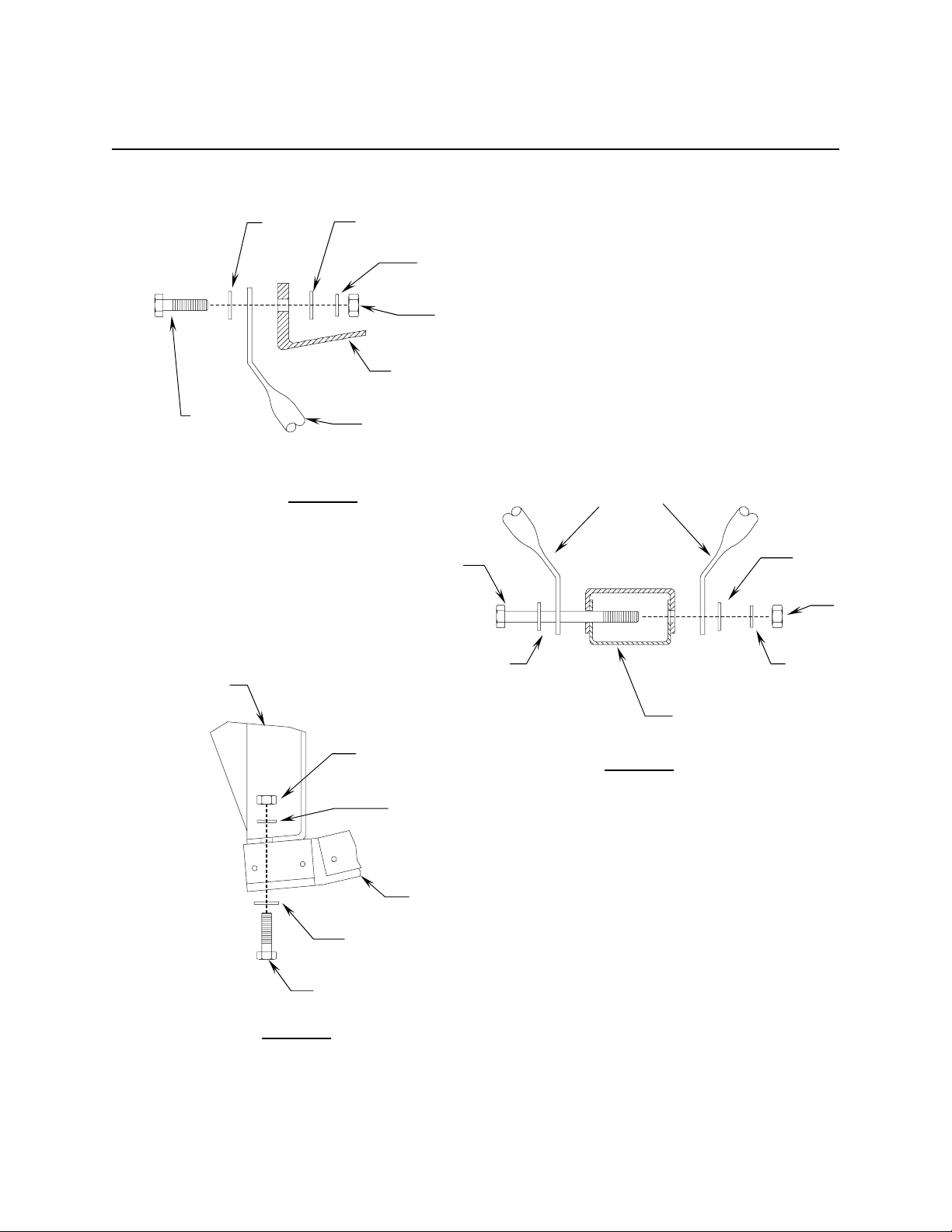
FEED SUPPORT PART LIST - TABLE 2.2
ITEM PART NO. DESCRIPTION QTY
1 VARIES Feed Rod 2
2VARIES Feed Support Tube 1
3 8030-008 3
4 8030-022 1
5 8201-040 8
6 8202-040 4
7 8100-007 4
1/4” x 1.00 Hex Bolt
1/4” x 3.00 Hex Bolt
1/4” Flatwasher
1/4” Lockwashe
r
1/4” Hex Nut
2.3 FEED SUPPORT ASSEMBLY
These instructions are intended as a general reference for feed support
assembly. If your antenna system has specific feed support installation
instructions, then refer to them at this time.
CAUTION: During the assembly procedure, the sequence of instructions
must be followed. DO NOT TIGHTEN ANY HARDWARE UNTIL
INSTRUCTED. Refer to the feed support parts list and steps.
4096-629
PRODELIN CORPORATION .89/.98M Ku-BAND Rx/Tx SERIES 1892/1982
12
STEP 1.
Attach the feed rods to the reflector
with 1/4” x 1.00 bolt (item 3) and secure
with 1/4” hardware (items 5, 6, 7).
See Detail “A”.
See Detail A
Feed Rods
STEP 2.
Connect the ends of the feed rods to
the feed support tube with 1/4” x 3.00
bolt (item 4) and secure with hardware
(items 5, 6, 7). See Detail “B”.
See Detail B
Feed Support Tube
STEP 3.
A) Attach feed support tube to the
bottom of the reflector with 1/4” x
1.00 bolt (item 3) and secure with
hardware (items 5, 6, 7).
B) Tighten the 1/4” hardware at the
reflector rim snugly. Next, tighten
the hardware that connects the
feed rods to the feed support tube.
C) Refer to separate instructions for
the specific feed/ODU assembly to
the feed support.
Feed Support
Tube
See Detail C
4096-629
PRODELIN CORPORATION .89/.98M Ku-BAND Rx/Tx SERIES 1892/1982
13
[ 6 ]
[ 5 ]
[ 5 ]
[ 7 ]
[ 3 ]
Reflector
Feed Rod
Feed Rods
Detail A
[ 7 ]
[ 5 ]
[ 4 ]
[ 6 ]
Feed Support Tube
[ 5 ]
Reflector
[ 6 ]
[ 7 ] Detail B
Feed Support Tube
[ 5 ]
[ 3 ]
Detail C

4096-629
PRODELIN CORPORATION .89/.98M Ku-BAND Rx/Tx SERIES 1892/1982
14
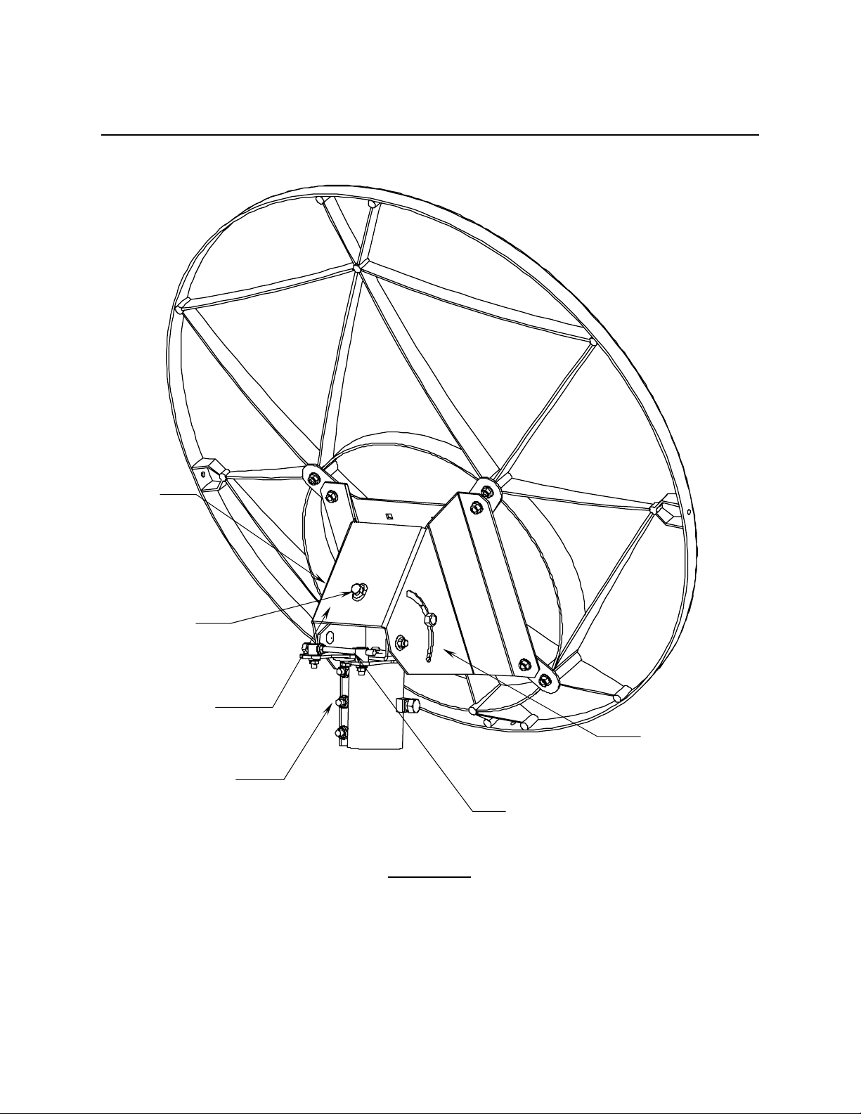
SECTION III ANTENNA POINTING
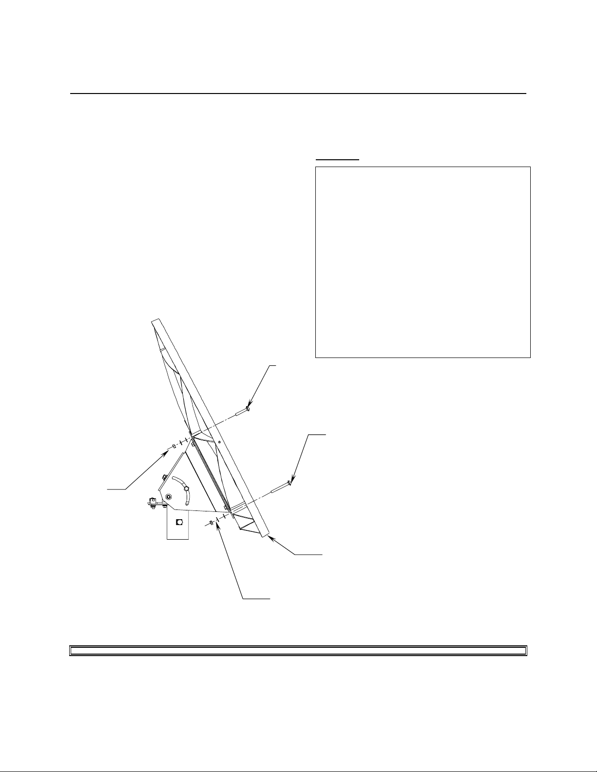
3.0 ANTENNA POINTING
The .89/.98 meter reflector contains a 16° elevation offset look angle. Therefore,
when the reflector aperture is perpendicular to the ground, the antenna is actually
looking 16° in elevation. Refer to Figure 2.
Note: The following alignment procedure is intended only as a general reference
guide for this antenna. For proper antenna performance, accurate
alignment is critical. Therefore, it is recommended that your own detailed
procedure be used or contact Prodelin’s Technical Support Department for
additional recommendations.
STEP 1: Adjust the reflector up or down in elevation by turning the 5/16” Bolt at the
az/el positioner until the desired elevation is read on the ‘B side’ of the
positioner. This scale is used for nominal readings and is accurate to ±2
degrees Note: Be sure that the elevation pivot hardware is loose enough
to allow adjustment without damaging (bending) the elevation rod. Snug
the hardware.
STEP 2: Azimuth Adjustment: With the electronics set to acquire the satellite,
rotate the antenna in azimuth until the satellite is found. Tighten the
canister hardware at this time.
STEP 3: Fine azimuth adjustment is achieved by loosening the three hex nuts
inside the Az/el positioner and turning the single hex bolt at the back of the
positioner in either direction.
STEP 4: Peak the antenna signal by fine adjustments made in both azimuth and
elevation until the optimum signal is achieved.
STEP 5: Tighten all hardware used for adjustment.
4096-629
PRODELIN CORPORATION .89/.98M Ku-BAND Rx/Tx SERIES 1892/1982
15
‘A side’
Scale not
used on this
system
Tighten
canister after
rough
adjustment
Reflector Support
‘B side’ scale
for elevation
adjustment
Fine azimuth
adjustment
Elevation
Adjustment Bolt
FIGURE 2.

4096-629
PRODELIN CORPORATION .89/.98M Ku-BAND Rx/Tx SERIES 1892/1982
16
SECTION IV MAINTENANCE
4.0 MAINTENANCE OVERVIEW
After installation, the antenna requires only periodic inspection. It is
anticipated that maintenance, if required, will be minimal and easily
handled by a local or in-house maintenance staff.
4.1 REFLECTOR
Prodelin's reflector does not require any maintenance. The composite
construction of the reflector is virtually impervious to any damages that could be
caused by weather or atmospheric conditions. It is only necessary to inspect for
any physical damage done by vandalism or very severe weather conditions.
Should any damage be detected to a portion of the reflector, contact the
Customer Service Department at Prodelin for recommendations involving
reflector repair.
4.2 MOUNT AND REFLECTOR SUPPORT STRUCTURE
The mount and reflector support structure supplied with this antenna is of steel
construction and has a powder painted finish.
If there are any signs of structural failure, the mount members that are damaged
should be repaired or replaced.
4.3 FEED AND FEED SUPPORT
The feed support and feed rods should be inspected to insure that all hardware is
secure. The feed/radio mounting bolts should be tight.
The feed horn window should be inspected to insure that it is intact so that no
moisture can collect inside the feed horn.
This manual suits for next models
1
Table of contents


