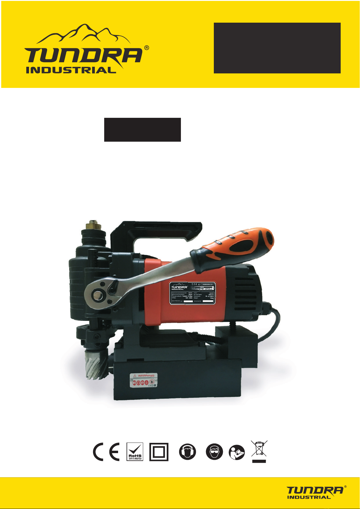
USER MANUAL
TUNDRMAGM40-110
TUNDRMAGM40-230
6
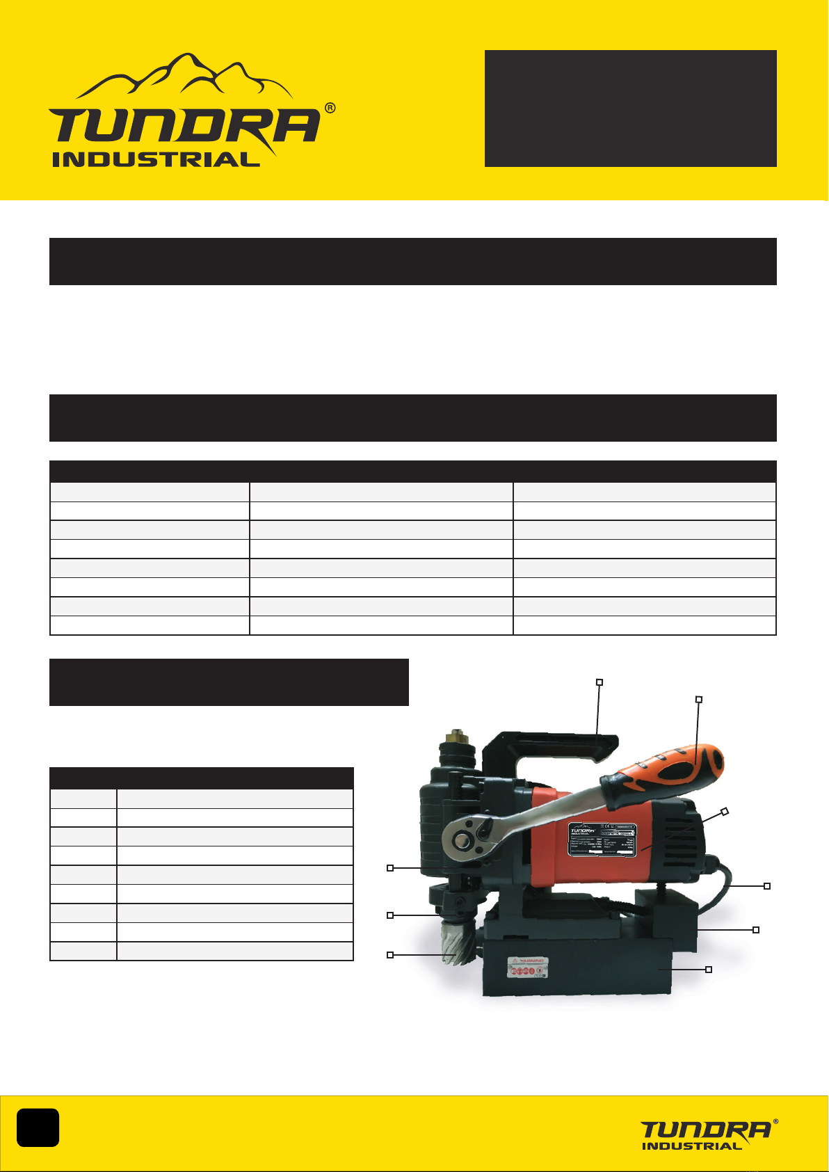
5. OPERATION GUIDE
1. Make sure the workpiece is suitable for magnetic adhesion and that both the surface of the workpiece and that the magnetic base of the drill is
clean and free of dirt, grease and debris.
2. Secure the magnetic drill to the unit to workpiece with safety chain provided.
3. Position the drill by sliding it and gently feeding the arbor so that pilot pin is in contact with the centre of the hole you need to cut.
4. Activate the magnet by pressing the MAGNET button to the ON position.
5. Turn the Feed Handle, raising the annular cutter until the pilot pin is above the work surface.
6. Open the cutting uid valve.
8. Make certain that the annular cutter is clear of the workpiece and turn the motor on by pressing the MOTOR button to the ON position.
9. Feed the cutter slowly onto the workpiece. Carefully establish a cutting depth of about 1/16" before using the full force of the drill on the cut by
turning the feed handle to lower the arbor as required.
10. Ease up on feed pressure as the cutter starts to break through the workpiece.
11. When you have completed the cut, turn off the motor by pushing the motor button into the STOP position.
12. Turn feed handles to raise the arbor away from the hole. This will cause the slug to fall free (if it hasn’t already) so take care to ensure it does
not fall in a way that can cause bodily harm to the operator or any other persons in the vicinity.
13. Turn the MAGNET OFF by pushing the magnet button to the OFF position. As the magnet de-activates the base should lift up off the work
surface.
14. Disconnect the equipment from the power source.
15. Remove any chips or debris from the cutter and the magnet wearing a pair of protective working gloves and a set of pliers to protect your
hands from sharp materials.
16. Disconnect the safety chain and carefully remove the drill to complete the procedure.
6. CLEANING & MAINTENANCE
• Keep the machine, the cutter and electric cables clean from drilling debris.
• Always turn off the machine and unplug from the mains before carrying out any cleaning.
• Clean the motor by means of dry compressed air.
• Clean and grease any sliding surfaces regularly.
• Carbon brushes should be replaced after approximately 250 hours running time.
• When not in use the magnetic drilling machine should be stored securely in the transport case lying at in a dry storage space.
Note: Excessive sparking may indicate the presence of dirt in the motor or worn out carbon brushes.
We recommend that you periodically check the brushes for wear and tear and replace them when they reach 6mm. Keep moving parts lubricated.
Maintenance, checks and repairs should only be made by qualied electricians or a Tundra Industrial approved technician.
We recommend that the machine should be serviced after approximately 250 hours running time.
Only use genuine spare parts. A full list is available at the end of this manual. Contact your nearest Tundra Industrial dealer for further
information.
Important: The magnetic strength of the drill base is related to the thickness of the steel ,or other ferrous
metal, in the workpiece. Magnetic adhesion can also be affected by the cleanliness of the metallic surface you are fixing to. Material
that is clean and free from coatings will offer the best surface for the magnet.
Factors that can reduce the effectiveness of the magnet and safe operation of the equipment include:
• Coatings or paint layers on material
• Material less than 3/8” thick
• Workpieces with dirt, grease or debris between the magnet and the metallic surface
• Curved or uneven work surfaces (The surface of the workpiece should be flat. For pipe applications, a pipe adapter should be used.)
• Workpieces that are smaller than the dimensions of the metallic base.