www.videoalarmtechnologies.com.au
INSTALLATION SHEET
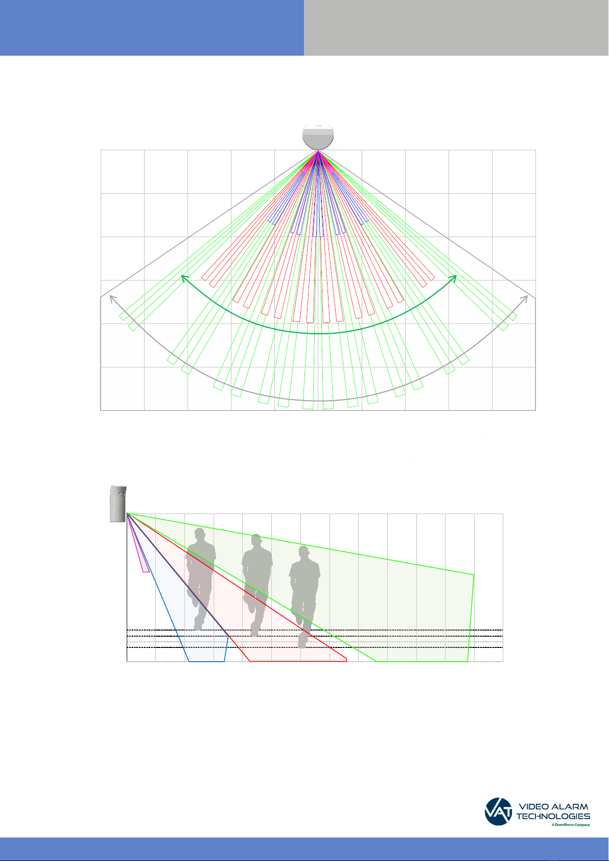
Indoor Motion Viewer IMV702
(EN) Security notes / (FR) Notes de sécurité / (DE) Hinweise zur Sicherheit
English Francias Deutsch
> Remove batteries before any mainte-
nance!
> WARNING, there is a risk of explosion if a
battery is replaced by an incorrect type!
> Observe polarity when setting up the
batteries!
> Do not throw used batteries! Bring them
to your installer or a collection point.
> Attention ! Il y a un risque d’explosion si
l’une des piles utilisées est remplacée par
une pile de type incorrect !
> Respectez la polarité lors de la mise en
place des piles !
> Ne jetez pas les piles usagées ! Ra-
menez-les à votre installateur ou à un point
de collecte spécialisé.
> Batterien vor jeglichen Wartungsarbeiten
entfernen!
> Vorsicht, es besteht Explosionsgefahr,
wenn eine Batterie durch eine Batterie
falschen Typs ersetzt wird!
> Achten Sie beim Einsetzen der Batterien
auf die Polung!
> Entsorgen Sie Batterien nicht im nor-
malen Haushaltsmüll! Bringen Sie Ihre
verbrauchten Batterien zu den öffentlichen
Sammelstellen.
FCC Regulatory Information for USA and CANADA
FCC Part 15.21 Changes or modifications made to this equipment not expressly approved by RSI VideoTechnologies may void the FCC
authorization to operate this equipment.
FCC Part 15.105 Class B
This equipment has been tested and found to comply with the limits for a Class B digital device, pursuant to Part 15 of the FCC Rules. These
limits are designed toprovide reasonable protection against harmful interference in aresidential installation. This equipment generates, uses
and can radiate radio frequency energy and, if not installed and used in accordance with the instructions, may cause harmful interference
to radio communications. However, there is no guarantee that interference will not occur in a particular installation. If this equipment does
cause harmful interference to radio or television reception, which can be determined by turning the equipment off and on, the user is
encouraged to try to correct the interference by one or more of the following measures:
• Reorient or relocate the receiving antenna.
• Increase the separation between the equipment and receiver.
• Connect the equipment into an outlet on a circuit dierent from that to which the receiver is connected.
• Consult the dealer or an experienced radio/TV technician for help.
Radio frequency radiation exposure information according 2.1091 / 2.1093 / OET bulletin 65
This equipment complies with FCC radiation exposure limits set forth for an uncontrolled environment. This equipment should be installed
and operated with minimum distance of 20 cm between the radiator and your body.
This transmitter must not be co-located or operating in conjunction with any other antenna or transmitter.
This device complies with Part 15 of the FCC Rules and with RSS-210 of Industry Canada.
Operation is subject to the following two conditions:
(1) This device may not cause harmful interference, and
(2) This device must accept any interference received, including interference that may cause undesired operation.
Cet appareil est conforme à la Partie 15 des règlementations de la FCC et avec la norme RSS-210 de l’Industrie Canadienne.
Son fonctionnement est soumis aux deux conditions suivantes :
(1) Cet appareil ne doit pas causer d’interférences nuisibles et