VOITAS V11 5 M User manual
#
USER MANUAL
VOITAS V11 5 M / 8 M
RELEASE DATE: JULY 2023, REV. 1.1

User Manual
Table of Contents
Electrical Safety Instructions
1
Introduction
2
Drawings & Dimensions
3
Installation
4
Installation Guide
5
First Use & Set-up
9
Charging Process
10
RFID
11
Residual Current Device (RCD) Type B
12
LED Effects
13
Datasheet
14
User Manual
Table of Contents
Electrical Safety Instructions
1
Introduction
2
Drawings & Dimensions
3
Installation
4
Installation Guide
5
First Use & Set-up
9
Charging Process
10
RFID
11
Residual Current Device (RCD) Type B
12
LED Effects
13
Datasheet
14
12
Electrical Safety Instructions
WARNING!
Please keep a copy of this manual throughout the
life of the product. This document contains the
information necessary for the safe installation and
use of the VOITAS V11 electric vehicle charger.
Before using it for the first time, read the entire
contents of the manual, especially the Electrical
Safety Instructions.
VOITAS V11
VOITAS Innovations GmbH is not responsible for the
material damage caused by failure to follow
installation and operating instructions, use of
unauthorized spare parts or accessories, or
employment of unqualified personnel. Use of the
VOITAS V11 is permitted only if the installation has
been carried out according to the instructions in
this User Manual by a qualified electrician. Safety-
threatening malfunctions must be corrected only by
qualified personnel. You can contact the VOITAS
Innovations technical support through our website
https://voitas-innovations.com/pages/kontakt.
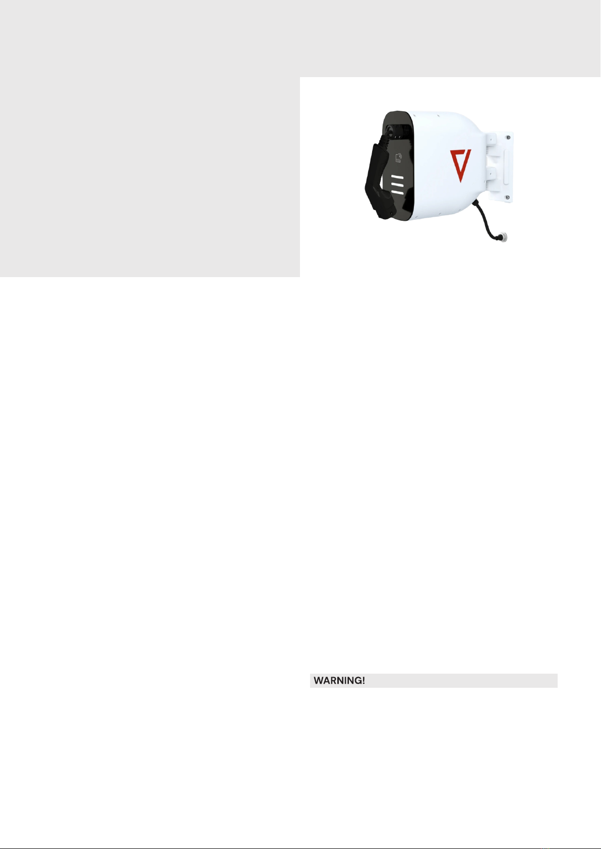
• We recommend installing the VOITAS V11
indoors or under the roof, without direct
sunlight to prevent overheating. The VOITAS V11
reduces charging power when the temperature
is too high.
• Do not install the VOITAS V11 in an area prone to
flooding or direct water spray.
• Make sure that the power supply is turned off
before you start cleaning your VOITAS V11. Do
not clean your charger with spray or direct
stream of water. We recommend the use of a
slightly damp cloth soaked in a mild solvent-
free and non-scouring cleaning agent.
• The VOITAS V11 is essentially maintenance free
but the owner should regularly check the
sockets, charging connectors and the cable as
well as the housing for visible damage. It is
recommended to make sure that the interior of
the connector is clean and free from any dirt
(e.g. sand, pieces of twigs or leaves) before
each charge.
• The charger must be grounded (PE wire
connected and properly routed in the electrical
system).
• The minimum unwinding of the cable is marked
with a yellow label, and the maximum
unwinding value with a red label.
•The attached water protection cap should seal
the type 2 plug if not in use to prevent damage
from dust or water.
• The VOITAS V11 is equipped with thermal
protection inside the cable reel. If the
temperature exceeds 80°C, the power
supply is disconnected automatically.
VOITAS V11 complies with the following directives
and most important harmonized norms: EU (LVD)
Directive 2014/35/EU, EU (EMC) Directive
2014/30/EU, EU (RED) Directive 2014/53 /EU,the
Electrical Equipment (Safety) Regulations 2016,
RoHS, PN-EN IEC 61851-1:2019-10E, PN-EN IEC
61316:2022-04,PN-EN 62196-2:2017-06.
Important note on the correct disposal of the
product based on Directive 2012/19/EU. The product
must not be disposed of with household waste. It
must be recycled at a special collection point for
used electrical appliances.
Always unwind the cable at least up to the yellow
label when charging to avoid overheating of the
device.
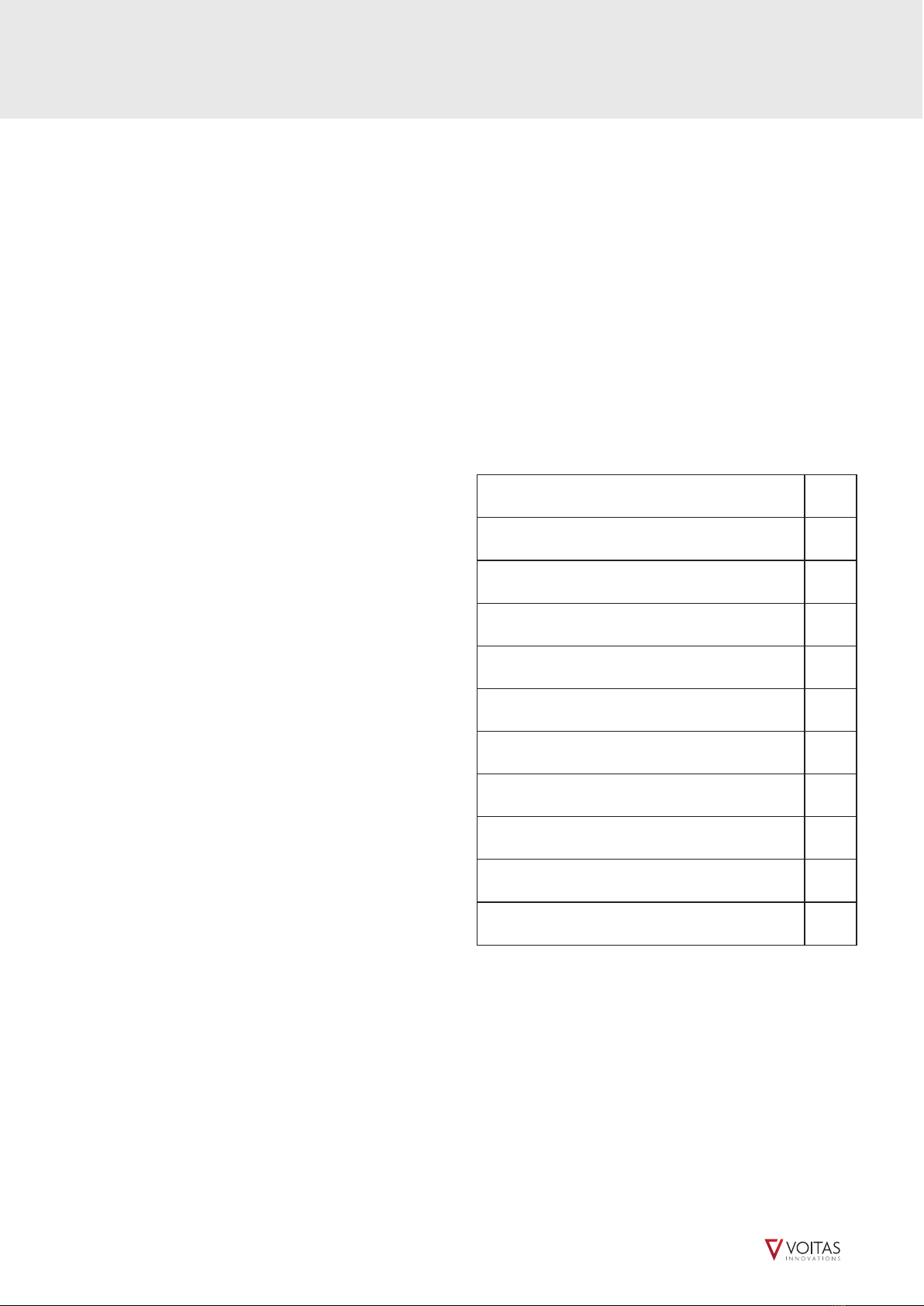
Introduction
Thank you for choosing our product!
The VOITAS V11 is a part of an extendable EV charging
system that allows for safe, convenient, and efficient
charging of EVs.
The system consists of:
• The VOITAS V11 - an EV charger that can be
purchased with VOITAS RFID tokens, residual
current device (RCD) type B protection and two
cable lengths - 8 and 5 meters. The VOITAS V11
can work independently or be paired with the
VOITAS Smart Meter.
• The VOITAS App from which you are able to
manage settings, users, see statistics and reports
on charging history. Make sure your mobile and
VOITAS V11 are connected to the same Internet
network and are operating on the same Ghz
frequency. Also allow access to the location on
your mobile.
• The VOITAS Smart Meter - a two-way energy
meter, installed in electrical systems where there
is a photovoltaic installation (or another form of
energy production). Its main task is to monitor
the electrical system for excess energy. With this
data, the VOITAS V11 can adjust the charging
power to use only the energy generated from the
photovoltaic installation.
• An RFID authentication feature allows user
authentication, preventing unwanted use of the
VOITAS V11 where the charger is installed in a
public area.
• The residual current device (RCD) module is an
additional safety measure. It provides built-in
differential current monitoring and electric
shock protection.
For more information on our charging system or
other products, please visit: www.voitas-
innovations.com.
VOITAS V11 nameplate
The nameplate is located at the back of the device
between the fixing points. If you want to read the
entire nameplate, move the VOITAS V11
approximately 90 degrees to the wall.
S/N placed on the nameplate indicates the serial
number of the VOITAS V11.
NOTE:
The serial number (S/N) is required to register your
device in the VOITAS App.
V11 nameplate

12
Electrical Safety Instructions
WARNING!
Please keep a copy of this manual throughout the
life of the product. This document contains the
information necessary for the safe installation and
use of the VOITAS V11 electric vehicle charger.
Before using it for the first time, read the entire
contents of the manual, especially the Electrical
Safety Instructions.
VOITAS V11
VOITAS Innovations GmbH is not responsible for the
material damage caused by failure to follow
installation and operating instructions, use of
unauthorized spare parts or accessories, or
employment of unqualified personnel. Use of the
VOITAS V11 is permitted only if the installation has
been carried out according to the instructions in
this User Manual by a qualified electrician. Safety-
threatening malfunctions must be corrected only by
qualified personnel. You can contact the VOITAS
Innovations technical support through our website
https://voitas-innovations.com/pages/kontakt.
• We recommend installing the VOITAS V11
indoors or under the roof, without direct
sunlight to prevent overheating. The VOITAS V11
reduces charging power when the temperature
is too high.
• Do not install the VOITAS V11 in an area prone to
flooding or direct water spray.
• Make sure that the power supply is turned off
before you start cleaning your VOITAS V11. Do
not clean your charger with spray or direct
stream of water. We recommend the use of a
slightly damp cloth soaked in a mild solvent-
free and non-scouring cleaning agent.
• The VOITAS V11 is essentially maintenance free
but the owner should regularly check the
sockets, charging connectors and the cable as
well as the housing for visible damage. It is
recommended to make sure that the interior of
the connector is clean and free from any dirt
(e.g. sand, pieces of twigs or leaves) before
each charge.
• The charger must be grounded (PE wire
connected and properly routed in the electrical
system).
• The minimum unwinding of the cable is marked
with a yellow label, and the maximum
unwinding value with a red label.
•The attached water protection cap should seal
the type 2 plug if not in use to prevent damage
from dust or water.
• The VOITAS V11 is equipped with thermal
protection inside the cable reel. If the
temperature exceeds 80°C, the power
supply is disconnected automatically.
VOITAS V11 complies with the following directives
and most important harmonized norms: EU (LVD)
Directive 2014/35/EU, EU (EMC) Directive
2014/30/EU, EU (RED) Directive 2014/53 /EU,the
Electrical Equipment (Safety) Regulations 2016,
RoHS, PN-EN IEC 61851-1:2019-10E, PN-EN IEC
61316:2022-04,PN-EN 62196-2:2017-06.
Important note on the correct disposal of the
product based on Directive 2012/19/EU. The product
must not be disposed of with household waste. It
must be recycled at a special collection point for
used electrical appliances.
Always unwind the cable at least up to the yellow
label when charging to avoid overheating of the
device.
Introduction
Thank you for choosing our product!
The VOITAS V11 is a part of an extendable EV charging
system that allows for safe, convenient, and efficient
charging of EVs.
The system consists of:
• The VOITAS V11 - an EV charger that can be
purchased with VOITAS RFID tokens, residual
current device (RCD) type B protection and two
cable lengths - 8 and 5 meters. The VOITAS V11
can work independently or be paired with the
VOITAS Smart Meter.
• The VOITAS App from which you are able to
manage settings, users, see statistics and reports
on charging history. Make sure your mobile and
VOITAS V11 are connected to the same Internet
network and are operating on the same Ghz
frequency. Also allow access to the location on
your mobile.
• The VOITAS Smart Meter - a two-way energy
meter, installed in electrical systems where there
is a photovoltaic installation (or another form of
energy production). Its main task is to monitor
the electrical system for excess energy. With this
data, the VOITAS V11 can adjust the charging
power to use only the energy generated from the
photovoltaic installation.
• An RFID authentication feature allows user
authentication, preventing unwanted use of the
VOITAS V11 where the charger is installed in a
public area.
• The residual current device (RCD) module is an
additional safety measure. It provides built-in
differential current monitoring and electric
shock protection.
For more information on our charging system or
other products, please visit: www.voitas-
innovations.com.
VOITAS V11 nameplate
The nameplate is located at the back of the device
between the fixing points. If you want to read the
entire nameplate, move the VOITAS V11
approximately 90 degrees to the wall.
S/N placed on the nameplate indicates the serial
number of the VOITAS V11.
NOTE:
The serial number (S/N) is required to register your
device in the VOITAS App.
V11 nameplate

34
Drawings & Dimensions
Cable reel zone
Service zone - dedicated
to the installer
VOITAS V11 zone -
sealed and separated
functional electronics
Isometric view
Installation
NOTE:
For detailed instructions on how to install and
connect the VOITAS V11, see Installation Guide
section.
To ensure the safe use of the VOITAS V11, the user is
required to install the device according to the
instructions in this manual.
It is necessary to protect the VOITAS V11 against all
weather conditions. Our warranty will not cover the
damage caused by adverse weather conditions.
Direct sunlight may overheat the VOITAS V11,
causing a reduction in charging power. This can
turn off the charging cycle.
The charger must be located where it is protected
against the danger of explosion or flooding.
Installation in areas with high humidity is not
recommended. Always follow the instructions for
low-voltage electrical installations according to IEC
60364-1 and IEC 60364-5-52.
Service plate
Front view Top view
Side view
182 124
469
397
352
263
124
NOTE: All dimensions are in milimeters.

56
Installation Guide
TOOLS NEEDED:
drill,
6 mm drill bit,
T25 screwdriver,
level,
marker,
wire cutting pliers,
wire stripper,
T20 screwdriver
Mount the VOITAS V11 to the wall on the dedicated
bracket included with the Wallbox or to one of the
two types of VOITAS Bases (posts designed for
concrete or drill) that can be purchased separately.
MOUNTING THE BRACKET
NOTE:
All the screw wall plugs and screws needed to mount
the bracket are included with the V11.
The surface for mounting the bracket must be flat,
solid and resistant to mechanical pressure.
1. Place the template on the flat surface for installation
and align it vertically using a level.
2. Mark the four mounting openings on the wall
surface using a template.
3. Drill the openings in the wall to a depth of at least
65 mm.
4. Hammer in the screw wall plugs.
5. Place the bracket on the wall and drive the M5x80
screws into the screw wall plugs.
6. Make sure the screws are tightened firmly.
7. Hang the V11 on the bracket.
8. Secure the V11 against slipping out of the bracket
using an M4 screw.
Side view
Mount the V11
Mark four drilling openings
using a template
Align the bracket vertically
Hammer in the screw wall plugs
Isometric view
Secure with an M4 screw
Installation Guide
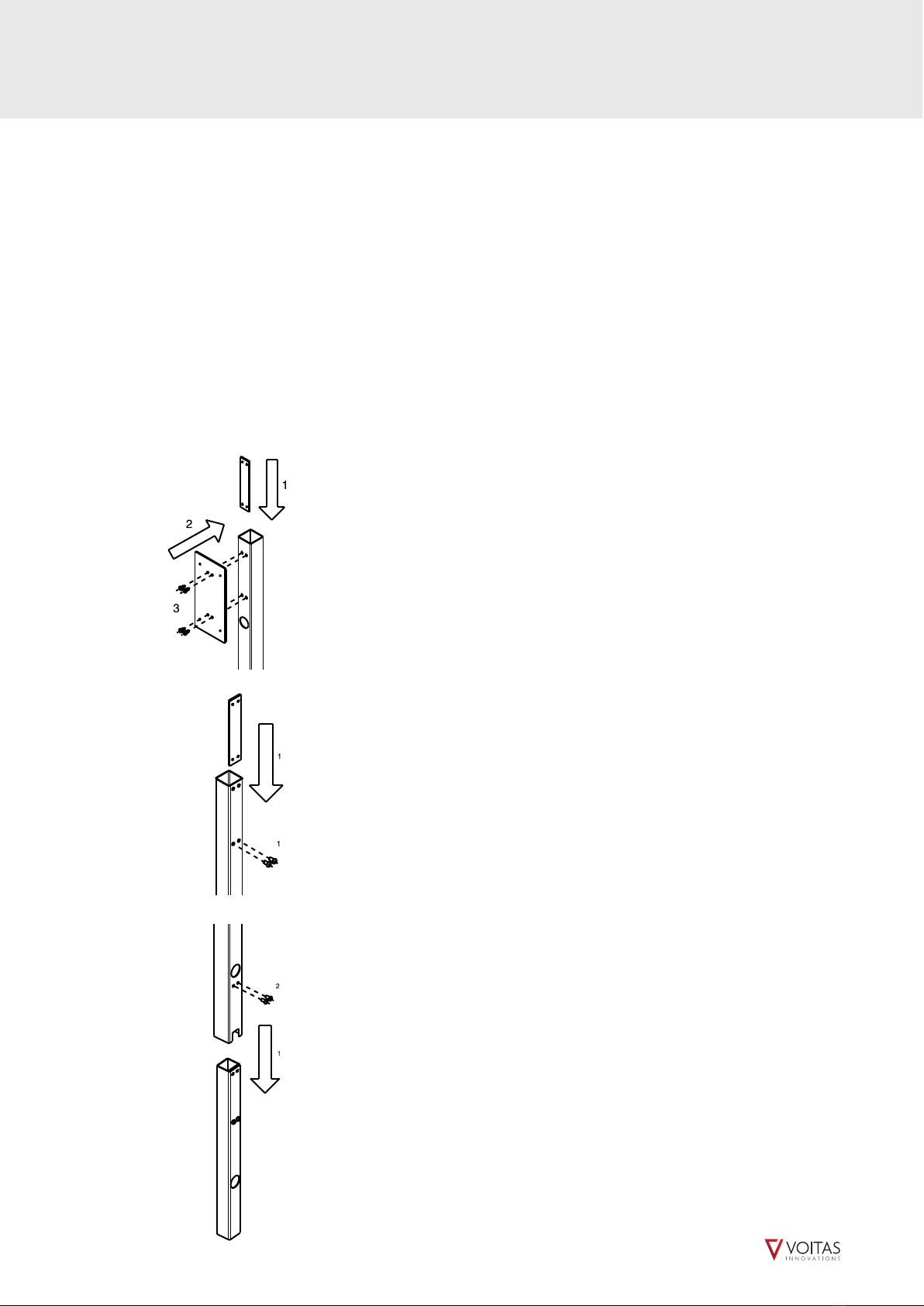
MOUNTING THE POST
NOTE:
All the screws, anchors and washers needed to
mount the post (for concrete or drill respectively) are
included in the VOITAS Base kit.
STEP 1:
1. Place the threaded flat bar inside the post and
position it in place of the holes drilled in the post.
2. Position the mounting plate in place of the holes
drilled in the post.
3. Screw the mounting plate, the post and the flat bar
together using M8 screws.
STEP 2:
1. Insert the threaded flat bar into the inside of the
post with the smaller cross section and attach it with
two M8 screws.
STEP 3:
1. Slide the post with the larger cross-section over
the post with the smaller cross-section.
2. Screw the two posts together using two M8 screws.
STEP 1
STEP 2
STEP 3
56
Installation Guide
TOOLS NEEDED:
drill,
6 mm drill bit,
T25 screwdriver,
level,
marker,
wire cutting pliers,
wire stripper,
T20 screwdriver
Mount the VOITAS V11 to the wall on the dedicated
bracket included with the Wallbox or to one of the
two types of VOITAS Bases (posts designed for
concrete or drill) that can be purchased separately.
MOUNTING THE BRACKET
NOTE:
All the screw wall plugs and screws needed to mount
the bracket are included with the V11.
The surface for mounting the bracket must be flat,
solid and resistant to mechanical pressure.
1. Place the template on the flat surface for installation
and align it vertically using a level.
2. Mark the four mounting openings on the wall
surface using a template.
3. Drill the openings in the wall to a depth of at least
65 mm.
4. Hammer in the screw wall plugs.
5. Place the bracket on the wall and drive the M5x80
screws into the screw wall plugs.
6. Make sure the screws are tightened firmly.
7. Hang the V11 on the bracket.
8. Secure the V11 against slipping out of the bracket
using an M4 screw.
Side view
Mount the V11
Mark four drilling openings
using a template
Align the bracket vertically
Hammer in the screw wall plugs
Isometric view
Secure with an M4 screw
Installation Guide
MOUNTING THE POST
NOTE:
All the screws, anchors and washers needed to
mount the post (for concrete or drill respectively) are
included in the VOITAS Base kit.
STEP 1:
1. Place the threaded flat bar inside the post and
position it in place of the holes drilled in the post.
2. Position the mounting plate in place of the holes
drilled in the post.
3. Screw the mounting plate, the post and the flat bar
together using M8 screws.
STEP 2:
1. Insert the threaded flat bar into the inside of the
post with the smaller cross section and attach it with
two M8 screws.
STEP 3:
1. Slide the post with the larger cross-section over
the post with the smaller cross-section.
2. Screw the two posts together using two M8 screws.
STEP 1
STEP 2
STEP 3

78
Installation Guide
MOUNTING THE BASE OF THE POST TO THE
GROUND
WITH DRILL VERSION:
Attach the base of the post to the ground using four
M12 concrete anchors.
NOTE:
To seal the holes in the base of the post, use the four
M12 washers for the anchors included in the kit. The
use of washers is required to ensure the stability of
the anchor installation.
WITH CONCRETE VERSION:
Concrete the lower part of the post in the ground up
to the minimum height of 390 mm. The part of the
post above the ground should be about 1,3 metres
high.
MOUNTING THE BRACKET TO THE POST
1. Attach the Wallbox bracket to the post with M6
screws. Make sure the screws are tightened firmly.
2. Place the V11 in the bracket.
3. Secure the V11 against slipping out of the bracket
using an M4 screw.
Installation Guide
Make sure that the electrical installation can
support a continuous supply of 16A per phase
(among other things, the overcurrent protection
in this segment is at least 16A, and the wires have
the appropriate cross-section).
CONNECTING THE V11 TO THE ELECTRICAL
SYSTEM
NOTE:
For convenience when connecting to the
electrical system, remove the VOITAS V11 from
the bracket.
A power cable is included with the VOITAS V11. A 5
x 2,5mm2 section with a length of 50 cm has been
added and installed. On the installer's side, the
operation consists of preparing a junction box in
which they will connect and secure the cables. We
recommend that the installation cable between the
V11 and the junction box is not routed out of the
Wallbox at an angle greater than 45 degrees to
avoid tension.
Make sure the wires are connected according to
the colours:
L1 - phase 1 - brown,
L2 - phase 2 - black,
L3 - phase 3 - grey,
N - neutral - blue
PE - protective conductor - green-yellow
CONNECTING THE V11 TO THE LOCAL NETWORK
1. Unscrew the service plate.
2. Find the grommet located at the bottom of the
device.
3. Cut the grommet or pierce it with the Ethernet
Rj45 connector.
4. Insert the cable inside the housing.
5. Plug the Ethernet cable into the Ethernet socket.
6. Screw on the service plate.
Do not install the VOITAS V11 in areas where the
PE cable is missing! The charger will not work
properly.
Unscrew the service plate
Side view
Isometric view
Insert the cable
inside the housing
The post base
- with concrete version
390 mm
The post base
- with drill version

910
First Use & Set-up
FIRST USE AND SET-UP
When the VOITAS V11 is installed and connected
according to the instructions, you can proceed with
the device configuration. Make sure the VOITAS V11 is
within the range of your Wi-Fi network or connected
to your network via an Ethernet port.
The Ethernet port is located near the power
connection of the VOITAS V11.
If the device does not respond, make sure the
power switch is on (the power supply switch is set
to position '1').
The VOITAS V11 will turn on its access point itself.
Launch the VOITAS App on your phone and register
the account.
Make sure location/GPS and mobile data on your
smartphone are switched on. The App will guide you
through the process of assigning the VOITAS V11 to
your account and connecting it to your home Wi-Fi
network.
Once you have assigned the VOITAS V11 to your
account, you can manage it from the App level.
NOTE:
At the first start it is recommended that the VOITAS
V11 is connected to the Internet to get the latest
updates. Please wait around 60 minutes to let the
device update and restart itself. The VOITAS V11
searches for Over-the-air Updates every hour.
Charging Process
CHARGING PROCESS
After the first use, the charging process goes as
follows:
1. Check the LED panel. If it glows white, the VOITAS
V11 is ready for charging. If you purchased VOITAS
RFID tokens you can use the functionality of the RFID
reader mounted in the Wallbox. RFID configuration is
available in the VOITAS App.
2. (RFID VERSION ONLY) place the RFID token on the
front panel of the Wallbox, above the LED strips in
the area marked by the sticker. After successful
authorization, a green tick will appear on the LED
strips.
3. Open the cover of the vehicle's charging socket
and unwind the cable. The cable reel integrated into
the VOITAS V11 has a locking mechanism - it locks
itself with each rotation and locks the cable. The
VOITAS V11 is equipped with a mechanism preventing
the automatic cable winding, locking the wire in the
desired position. To unlock the mechanism slightly
pull the wire for it to automatically rewind.
4. Connect the cable to your vehicle. Charging will
start automatically, and LED bars will indicate that
the charging process is in progress.
5. If you want to stop charging, disconnect the cable
from the vehicle. The VOITAS V11 will recognize this
and signal a return to standby.
6. Disconnect the cable and pull it to unlock the
mechanism and safely rewind the cable into the
VOITAS V11.
The VOITAS V11 8 M requires at least 5 meters of a
cable to be unrolled, and the VOITAS V11 5 M
requires at least 2 meters to be unrolled.
The cables have a spot marked with a yellow label,
which you will see when unwinding the cable. If
this label is not visible, the power during the
charging process will be reduced or interrupted as
the cable may heat up.
Do not let go of the cable until it is rolled up again.
CHARGING PARAMETERS
The user can control many parameters of the
charging process using the VOITAS App in the
Settings section.
You can change the charging mode from 'Grid' (no
change in charging power) to 'Solar' (charging using
excess energy from the photovoltaic installation).
The maximum charging current, and the number of
phases, can be changed manually using the slider in
the application under 'Settings'. First set the Wallbox
to 'Off' with the slider and then switch the phases to
'One/Three phases'. Then set the slider back to 'On'.
By default, the VOITAS V11 charges with a maximum
current of 16A per phase.

11 12
RFID
RFID
RFID identification is an optional feature of the
VOITAS V11, which can be added in the configuration
step when ordering the VOITAS V11. Please note that
the RFID function of the VOITAS V11 only works with
VOITAS RFID tokens.
It allows to secure the unit and verify the user. RFID
tokens are assigned to individual user accounts in the
VOITAS App in the configuration section in local Wi-
Fi-mode (see detailed instructions in the VOITAS
App).
When the RFID function is enabled, an additional
verification step is triggered. To start charging, the
user must scan the registered RFID token. This
operation needs to be repeated for every charging
cycle.
NOTE:
In this setting, without RFID authentication, the
VOITAS V11 will not respond to being connected to the
car.
The RFID reader is located on the front panel of the
Wallbox, above the LED strips in the area marked by
the sticker.
RFID reader
Residual Current Device (RCD) Type B
RCD - DIFFERENTIAL CURRENT MONITORING AND
ELECTRIC SHOCK PROTECTION
The VOITAS V11 is equipped with an RCD module type B
(AC 30 mA/DC 6mA) that monitors the level of residual
current and the continuity of the PE wire. In case of
damage to any of the charging elements (both the
VOITAS V11, or electric vehicle being charged) the RCD
module ensures that the user is additionally protected
against electric shock.
If the RCD module detects a fault, it will cut off the
power of the VOITAS V11. To reset the RCD module,
press the button: 'Reset RCD' in the App (go to
„Configuration” -> „Wallbox” -> „Basic”) or restart the
device, by opening the service flap and turn the power
off and on. In the LED-overview you find out how to
recognize a RCD module fault.
NOTE:
RCD reset will only work in offline mode.
Please note that electrical safety regulations vary
based on location. In some regions, the charging
station must be protected by an additional,
externally mounted RCD device.
Technical parameters of the RCD included in the
VOITAS V11:
Type B differential current monitoring device.
Min. differential current: 14.1 mA RMS.
Voltage Rating: 230V/400V 50 Hz.
Controlled switching device: the VOITAS V11 main
relays.
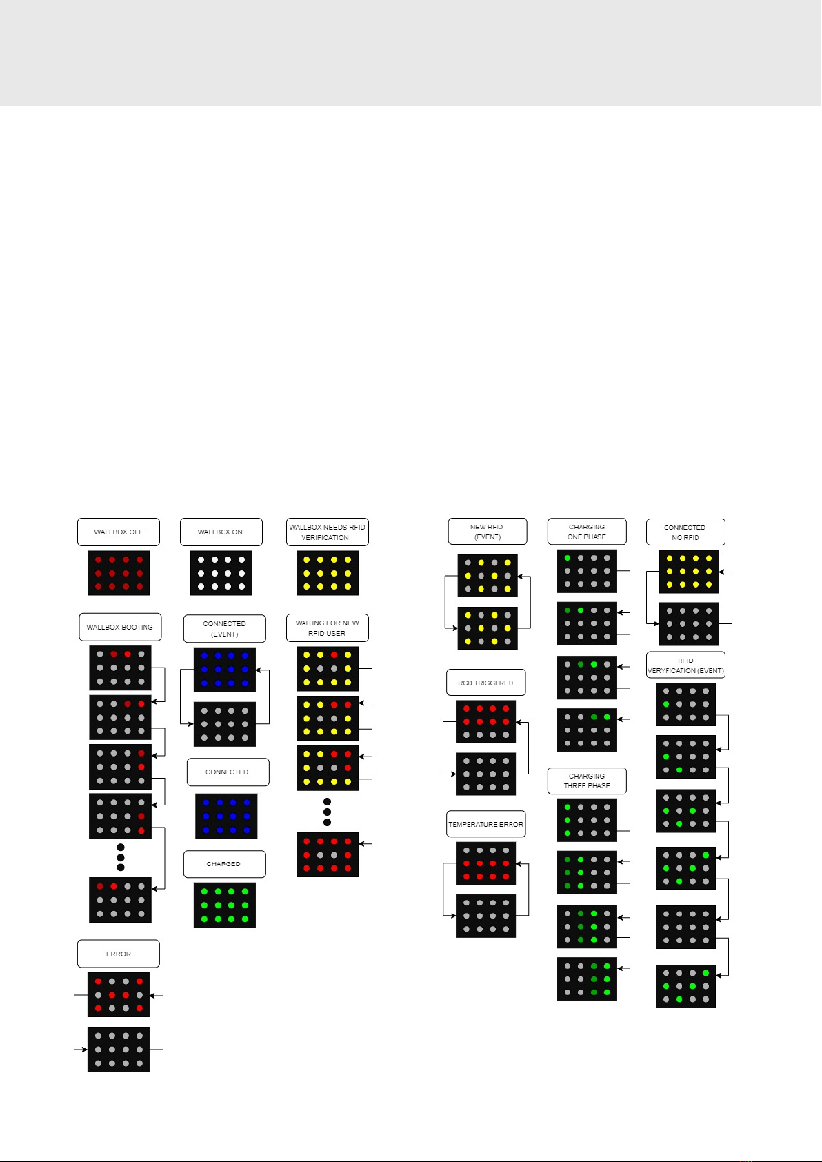
13 14
LED Effects
DISPLAY MARKINGS
The VOITAS V11 has three LED bars on the front panel
to indicate different states and modes.
Datasheet
Dimensions
395x350x182 [mm]
Weight
7 kg for the 8 M version
6,2 kg for the 5 M version
Ingress protection
IP 54
Working ambient temperature range
From -25 °C to 40 °C
Mounting
Dedicated mounting bracket, mounted on an indoor
wall or under a roof
Cable
5 M and 8 M versions, integrated cable reel
POWER / CHARGING
MECHANICAL DATA
Nominal load current / voltage / v. frequency
3,7 kW (1 phase) - 16A/230V/50Hz
11 kW (3 phases) - 16A/400V/50Hz
Charging current range
6 - 16A
Charging power
3,7 kW - 11 kW (3 phases)
1,4 kW - 3,7 kW (1 phase)
Charging mode
IEC 61851-1, mode 3
Connection to the vehicle
Type 2 plug
Shock protection
Residual current device (RCD Type B), PE conductor
continuity monitoring

15 16
Datasheet
ADDITIONAL INFO
Communication
WLAN, LAN, MODBUS TCP
RFID verification
Optional
Additional accessoires (optional)
VOITAS Smart Meter, VOITAS RFID tokens, VOITAS
Base
App control
Yes
Compliance with norms, directives and certificates
EU (LVD) Directive 2014/35/EU, EU (EMC) Directive
2014/30/EU, EU (RED) Directive 2014/53 /EU,the
Electrical Equipment (Safety) Regulations 2016,
RoHS, PN-EN IEC 61851-1:2019-10E, PN-EN IEC
61316:2022-04,PN-EN 62196-2:2017-06

17 #
17
www.voitas-innovations.com
USER MANUAL (ENG)
Other manuals for V11 5 M
1
This manual suits for next models
1
Table of contents
Other VOITAS Batteries Charger manuals


