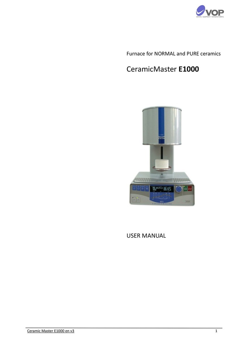
VOP CeramicMaster E20 User manual

Ceramic Master E20 en v1 1
CeramicMaster
E20
USER MANUAL

Ceramic Master E20 en v1 2
CONTENT
1. INTRODUCTION
2. SAFETY INSTRUCTIONS
3. DESCRIPTION OF THE UNIT
4. INSTALLATION AND INITIAL START-UP
5. PRACTICAL USE
Description of buttons
Description of indication
Parameters and Programming
Description of parameters in order of their
appearance
6. ERRORS AND FOLLOWING ACTIONS
7. IMPORTANT PRACTICAL INFORMATION
8. TECHNICAL DATA
9. AUTOCALIBRATION
10. USER SOFTWARE
11. MAINTENANCE
12. SCOPE OF DELIVERY
WARRANTY
3
4
5
6
7
7
8
9
10
12
13
14
15
16
16
16

Ceramic Master E20 en v1 3
1. INTRODUCTION
Thank you for having purchased the CERAMICMASTER
E20furnace which, we are sure will all meet all your
needs and will satisfy your high demands.
This furnace has been designed according to the
requirements of latest industrial standards and we
guarantee that you will use it many years as your closest
assistant.
The furnace has a kit for auto calibration that can be
purchased separately. For more information, see section
9 - AUTOCALIBRATION.
However, inappropriate use may damage the
equipment and be harmful to personnel. Please observe
the relevant safety instructions and read the Operating
Instructions carefully.
We wish you pleasant and fruitful work with the
CERAMICMASTER E20.
USING SYMBOLS:
This symbol indicates that there is high
dangerous tension under the bonnet which it is put on.
This symbol indicates that the machine
complies with the requirements of the Directives for Low
Tension and Electromagnetic Compatibility as well as for
the Standards harmonized with them.

Ceramic Master E20 en v1 4
2. SAFETY INSTRUCTIONS
The following instructions must be observed in order
to avoid personnel injury or equipment failure.
CAUTION!
the furnace must not be run by an operator who
is not acquainted with these instructions;
before turning on the plug in the net contact
check if the voltage in the electrical network
correspond to the working tension. In case of
discrepancy, consult a specialist;
on no account do not alter the device;
the notices and stickers must be kept in good
condition so that they are easily readable; they
should not be removed!
the machine must not function in case of being
damaged and in position to injure the staff or a
third person;
keep the cables out of heat, oil and coarse
objects; do not catch the device by the cable
when you move it.
switch off the furnace and pull out the plug of
the feeder cable from the contact before each
cleaning or upkeep.
spare parts which are not specified by the
manufacturer cannot be used!
If the machine is used by such means not indicated by
the manufacturer, the provided protection can get worse!

Ceramic Master E20 en v1 5
3. DESCRIPTION OF THE UNIT
1 Cover of the chamber
2 Ceramic table
3 Lift table
4 Cooling pad
5 Front panel
7 Mains switch
8 Mains fuses - 8А/250V
9 Plug of power cord
10 Plug of pump’s power cord
11 Fuse for vacuum pump - 1,25А/250V
12 Nozzle of pump’s hose
13 Hose of the vacuum pump
14 Adapter
15 Vacuum pump
1
2
3
4
5
10
11
12
9
8
7
14
15
16

Ceramic Master E20 en v1 6
4. INSTALLATION AND INITIAL START-UP
UNPACKING
CONNECTIONS
SETTING THE TIME TO AUDIBLE SIGNALS
IMPORTANT!
Carefully remove modules from packages;
Make sure that the mains voltage is ~220V and
the socket is reliably grounded.
Connect pump supply cable to the terminal with
label "VACUUM PUMP" on the rear panel;
Connect the power supply cable to the terminal
with label "POWER" on the rear panel;
Connect vacuum hose to the vacuum fitting with
label "VACUUM” on the rear panel.
The net switch is on the rear panel, on the right.
Put the furnace in a position which enables its
easy engaging turning off from the master
switch as well as from the contact.
You can set the duration of the sound signaling at
the end of the program. For this purpose it is
necessary to perform the following:
Turn off the furnace;
Press RUN and STOP keys simultaneously;
Hold the buttons until the next message appears:
END CYCLE SOUND
00015
The current value can be changed by turning the
multifunction knob MFK. The new value is stored
by pressing the button PROG.
After turning the oven on display for a few
seconds will show SELF TESTING. Do not release
the buttons until this sign stands on display.

Ceramic Master E20 en v1 7
5. PRACTICAL USE
DESCRIPTION OF BUTTONS
PROG - puts the number of the program which is to be
performed into programming mode.
ESC -cancels all changes.
RUN
starts the chosen program when the indicator of
the button flashes in green;
permits the change of the chosen parameter
value in a programming mode.
STOP
stops the program at any moment;
stops the movement of the table at any position;
cancels all changes of the chosen parameter in a
programming mode;
recovers the normal working mode of the
furnace after error.
- closes manually the furnace. The button can
increase/decrease the chosen parameter value
with 100 by pressing it while turning the multi
functional rotary knob.
- opens manually the furnace . The button can
increase/decrease the chosen parameter value
with 10 by pressing it while turning the multi
functional rotary knob.
MFK - multifunctional button; It can choose programs or
parameters and set values.

Ceramic Master E20 en v1 8
DESCRIPTION OF INDICATION
This furnace has 2 LINE LCD display.
The LINE 1 shows following information:
Sector”№ PROGRAM” shows the number of the chosen
program for execution or the program for entering of
parameters;
Sector "H:MM:SS" - shows the time remaining to the end
of the executed program.
Sector"V %" - shows the depth of the vacuum in %.
Sector"°C" - Indicates the current temperature in the
chamber.
The LINE 2 shows following information:
Sector "MODE" –displays information of the current stage;
Sector "PROGRAM NAME" –shows the name of the
selected program.
Indicator 1: the furnace is in the phase of drying.
Indicator 2: the furnace is in the phase when the tempera-
ture increases to the value for firing.
Indicator 3: the furnace is in the phase of firing.
Indicator 4: the furnace is in the phase of cooling.
Indicator 5: the vacuum pump is switched on.
54
3
2
1

Ceramic Master E20 en v1 9
PARAMETERS AND PROGRAMMING
In order to change the value of a parameter it is
necessary to do the following steps:
There are two possible ways of leaving the programming
mode after you have finished with the changes in the
parameters’ value:
FIRST EXIT:
SECOND EXIT:
With the multi functional rotary knob MFKchose the
program which parameters you want to change;
Press button PROG. Indicator of the button RUN
begins to blink green/red and you can see on the
display:
XXX : YYYYYYYYYY SEE
PROGRAM NAME
The letter expressions means:
ХХX - number of program;
YYYYYYYYYY - name of program;
SEE - view data;
PROGRAM NAMЕ- parameter which to be
changed.
PROGRAM NAMЕis the first parameter which is
shown when you enter in PROGRAM mode. Turn
left/right the MFKin order to chose the parameter
you want to change;
Press button RUN in order to chose the value of the
parameter you want to change. If you have chosen
the first parameter you would see on the display:
XXX : YYYYYYYYYY SET
PROGRAM NAME
Indicator of the button RUN turns off and the red
indicator on the button STOP begins to blink.
Turn the MFRK to change the parameter value.
Press button STOP in order to leave the programming of
the current parameter. Indicator of the button RUN starts
to blink again in green/red which means that it is possible
to program the next parameter.
press button ESC. This will CANCEL all the changes that
are made in the parameters’ value in the program.
press button PROG. This will SAVE all the changes that
are made in the parameters’ value permanent.
The indicator of button RUN will flash in green in working
mode if the temperature defined by the parameter IDLE
TEMP is reached and if the temperature is not
reached it will flash in red.

Ceramic Master E20 en v1 10
DESCRIPTION OF PARAMETERS IN ORDER OF THEIR
APPEARANCE
PROGRAM NAME
IDLE TEMP
PREDRY TIME
DRY TEMP
DRY TIME
FIRE RATE
FIRE TEMP
FIRE TIME
COOL1 TIME
COOL2 TIME
VRUN TEMP
VRUN TIME
VSTOP TEMP
VSTOP TIME
this is a parameter for setting the name for current
program. Choose the position for desired letter by using
buttons and . Then choose the letter using MFK.
an idle temperature. This is the temperature which the
furnace keeps in STOP mode. Its value is from 150°C to
600°C but it can’t exceed (DRY TEMP-20)°C.
during this time the table stays in lower end position
when the temperature in the chamber is equal to
DRYTEMP. It can be changed from 0 s to 1 h.
drying temperature. Its value is from (IDLE TEMP+20)°C
to (FIRE TEMP-20)°C.
the time for moving the table from lower end position to
the medium position which is about 1cm from the upper
end position of the table. The temperature in the
chamber is DRY TEMP. It can be changed from 0s to 1h.
increase rate of the temperature for the firing. Its value is
from 30°C /min to 200°C /min.
increase rate of the temperature for the firing. Its value is
from 30°C /min to 200°C /min.
time for maintaining the temperature FIRE TEMP. It can
be changed from 0s to 30min.
during this time the table is about 1cm from the upper
end position. It can be changed from 0s to 1h.
time for opening the furnace to the lower end position.
It can be changed from 0s to 1h.
temperature which defines the start of the time VRUN
TIME. Its value is from 0°Cto 1250°C. If its value
exceeds the value of the parameter FIRE TIME, vacuum
will never start.
time which defines the start of the vacuum. It starts after
the firing chamber temperature reaches the value of the
parameter VRUN TEMP. It can be changed from 0s to
1h.
temperature which defines the start of the time VSTOP
TIME. Its value is from 0°Cto 1250°C. If its value
exceeds the value of the parameter FIRE TIME, vacuum
will never start.
time which defines the stop of the vacuum. It starts after
the firing chamber temperature reaches the value of the
parameter VSTOP TEMP. It can be changed from 0s to
1h.

Ceramic Master E20 en v1 11
HINTS
The content of each program can be viewed during the
performance. For this purpose the MFKshould be
turned.
The parameter values are displayed in series and stay on
the display for 3 seconds. However, if during this time the
button is pressed, the values are displayed while this
button is pressed.
Values of the parameters FIRE RATE, FIRE TEMP и FIRE
TIME can be changed during the execution of the
program. This can be done with the buttons PROG, ESC
and and with the turning of the multifunctional knob
MFK.
By pressing the button PROG during program execution,
display shows the value of the parameter FIRE RATE and
by MFKthe programmed value can be changed.
If you do not respond within the next three seconds, the
display shows the current stage of program execution.
In the same way, by pressing the ESC key can be changed
parameter FIRE TEMP, and by button you can change
the parameter FIRE TIME.
When programming the temperature conditions for
parameters IDLE TEMP, DRY TEMP and FIRE TEMP the
program temperature cannot be lower than this of the
previous parameter and at the same time higher than
this of the next parameter.
There is a possibility for fast changing of parameters
which have TEMPERATURE and TIME dimensions. When
you push the button and rotate the MFRK the value
will change by 100 points, and by pushing and rotate
the MFRK the value will change by 10 points.

Ceramic Master E20 en v1 12
6. ERRORS AND CORRECTIVE ACTIONS
General errors
Errors, connected with heating
Errors, connected with the movement of the table
Errors, connected to the vacuum
1- Mains frequency is not 50 Hz or 60 Hz.
15 - During running of a program: when the
temperature is increasing the needed rate of
increasing cannot be achieved.
19 - The required temperature is not reached for the
selected time.
20 - The required temperature can not be reached
during cooling.
21 - The selected temperature can not be reached
during heating.
22 - Temperature is higher than 1200°С.
23 - Temperature is lower than 5°С.
53 - the drying sensor is not reached for a certain
time when the furnace opens.
78 - the lower sensor is not reached for a certain
time when the furnace opens.
83 - the top sensor is not reached for a certain time
when the furnace closes and a program with
vacuum executes.
90 - it is not possible to reach the sensor for top
position.
91 - it is not possible to reach the sensor for lower
position.
92 - the working table cannot open.
93 - the drying sensor is not reached for a certain
time when the furnace closes.
28 - The selected vacuum is not reached for the
required time.
50 - There exists residual vacuum during the initial
power on procedure.
51 - After releasing the vacuum, for the required
time the vacuum is not released entirely.
75 - The vacuum can not be released in programming
mode.

Ceramic Master E20 en v1 13
7. IMPORTANT PRACTICAL INFORMATION
1. Avoid positioning of furnace and pump in the
immediate vicinity of heat sources (radiators).
2. Install the vacuum pump in a well-ventilated
locations. Ensure that the apertures in the frame plate
are free and that no foreign object can fall into the
furnace base.
3. Avoid placing any objects on the frame plate, place
only on the face cooling plate.
4. Ensure that the sealing ring in the furnace head and
the sealing rim of the furnace base are kept clean and
undamaged.
5. Close the chamber between working cycles, but not
tightly, and leave a distance of approximately 1 cm.
6. It is strongly recommended to use porous ceramic tray
(on request - № 81022).
WARNING! For precise operation of the device is
necessary tempering oven for half an hour before the
first use of the day. To do this after turning on the
furnace, run at least one program with an empty camera
and wait another 20 minutes.
7. If the power supply is interrupted during the working
process and:
a. If the temperature in the chamber has not
decreased by more than 15 degrees, the current
program will continue from the stage at which it
has been stopped.
b. If the temperature in the chamber has decreased
by more than 15 degrees, the following message
will appear on the display:
LONG TIME POWER OFF
In this case the program cannot continue. You have to
press the button STOP in order to exit this state.
The total number of the programs is 203 - with numbers
from 0 to 202. Programs from №1 to №18 have
parameters for ceramic NORITAKE. The manufacturer has
entered same parameters in all other programs.
The program №201 is devoted for calibration of the
furnace by means of a silver test.
The program №202 is designed for auto calibration using
the optional calibration kit.
It is responsibility of the customer to enter the data for
the ceramic that he uses before he starts working.

Ceramic Master E20 en v1 14
8. TECHNICAL DATA
1. Electrical supply
2. Power consumption
2.1. Furnace with vacuum pump
2.2. Furnace without vacuum pump
3. Category of overtension
4. Vacuum pump data
4.1. Suction capacity
4.2. Regulated vacuum level
5. Maximal firing temperature
6. Effective firing chamber dimensions
7. Overall dimensions of closed furnace:
7.1. Width
7.2. Length
7.3. Height
8. Model Weight
9. mber of programs
10. Working temperature
11. Level of environment pollution
12. The device is designed for usage in normal dental
premises up to 2000 m altitude above sea level.
13. The maximum relative humidity of the air must
be 80% for temperatures up to 31°С, decreasing
lineally to 50% relative humidity for temperature
40°С.
14. Working modes
14.1. Programming mode
Programming of the parameters is fully
described in chapter 7. PROGRAMMING.
14.2. Working mode
It shows the number of the executed program
and the parameters’ value of the ongoing
program phase.
The values of all parameters could be seen if
you use the Multi Functional Rotary Knob
MFK.
~230 V, ±10%, 50/60Hz
1700 W
1550 W
ІІ
22 l/min
0,1 to 0,9 bar
1200°С
Ф 95 мм; h 60 мм
265 мм
370 мм
565 мм
20 кg
203
5°С - 40°С
2

Ceramic Master E20 en v1 15
9. AUTOCALIBRATION
ATTENTION:
The furnace is optionally provided with a kit for
autocalibration, which is a ceramic table fitted with special
holders. A wire of pure silver 9999 is attached on them.
These holders are connected by wires to the other side of
which a special connector is mounted.
The auto calibration kit is put in place on the tray. The
connector is plugged in the socket labeled ACAL. This
socket is located at the rear side of the furnace.
After plugging on the upper left corner of the display the
sign * appears.
Start program 202. After about 2 hours the program ends.
If during the execution of the program there was a problem
and the silver wire is disconnected, when calculating
coefficient was outside the normal range, the display
shows:
Err: Bad value = KKKKK
TTTTT RRR AAAAA,
Where
ККККК is the wanted coefficient
ТТТТ.Т is the temperature at break
RR.R is the ambient temperature
ААААА is the value measured by ADC
( the normal range of the coefficient is between 10000 and
12000)
If during the execution of the program there was no
problem and autocalibration has proceeded normally, the
display shows:
Old = OOOOO New = KKKKK
TTTTT RRR AAAAA,
Where
OOOOO is the old coefficient
KKKKK is the new coefficient
ТТТТ.Т is the temperature at break
RR.R is the ambient temperature
The furnace beeps at the end of the program.
Perform the following actions:
Take out the plug from the socket ACAL;
Remove the auto calibration kit;
Place the working ceramic tray again.
Press the STOP button;
Once you press the STOP button, the furnace is restarted
and is ready for operation.
This accessory is sold separately.

Ceramic Master E20 en v1 16
10. USER SOFTWARE
11. MAINTENANCE
12. DELIVERY SCOPE
User can connect the oven to a PC via USB interface.
The manufacturer provides a special program
E20_User_Software, which can be used for
-Download user programs from the furnace;
-Upload editing programs to thefurnace;
-Updating the system software;
-Programming the furnace directly from the PC;
-Control through the PC.
Clean only with a dry or slightly moist cloth (no solvents!).
Change the safety locks with the announced valus only,
namely:
1.25A, slow (class T).
8A, slow (class T).
No repair activity by a service technician who is not
authorized by the manufacturer is allowed!
The lifting and carrying should be made only with the both
hands from below as the furnace stands on end.
No carrying and transportation in another state except for
vertical position is allowed!
Furnace CERAMICMASTER E20 1 pc.
Vacuum pump PVD-M22 1 pc.
Power cable 1 pc.
Flexible tube for the vacuum 1 pc.
Spare fuses
1.25А/250V 1 pc.
8A/250V 2 pc.
User Manual
PRODUCER: “VOP” Ltd.
2140 IZ “Microelectronika”
Botevgrad, Bulgaria
Теl. 0723 66303
Теl./Fax 0723 66304

Ceramic Master E20 en v1 17
Serial Number __________________
Invoice number _________________
Date __________________________
_______________________________________
CLIENT:
MANAGER of “VOP” Ltd
_______________________________________
Serial Number _____________
Invoice number __________________
Date _____________________
Voucher Manufacturer
“VOP” Ltd.
Mikroelectronika
2140 Botevgrad
Tel. 0723 66303
Tel./Fax 0723 6304
Ceramic Master E20
WARRANTY SHEET
“VOP” Ltd. warrants the consumer for proper operation of all parts and materials in this product
during a period of 12 months since the day of its purchase.
During this period VOP Ltd. or its authorized persons will repair on its own account all defects
which have occur during the normal operation of the machine.
Defects caused by improper transportation, storage and manipulation of the product or due to
malfunction of the electrical mains supply are repaired on the account of the customer.
This warranty shall become void if attempts are made to repair the product by persons not
authorized by the producer.
Table of contents
Other VOP Furnace manuals
Popular Furnace manuals by other brands
Trane
Trane UX1B040A9241A installation guide

VERDER
VERDER Carbolite Gero CTF 12/65/550 Installation, operation and maintenance instructions
Dettson
Dettson AMT400B34-SM1 PMA Installation instructions and homeowner's manual

Lennox
Lennox MPGA 075 B3 Application guide

International comfort products
International comfort products C9MPX installation instructions

Heatmor
Heatmor 100 CB instruction manual