Vulcan-Hart 3 Series Owner's manual

Vulcan®3-Series
Burnout Furnaces
Multi-Stage Programmable
Owner & Operator’s Manual
Models: 3-130 3-550 3-550A 3-550PD 3-1750 3-1750A
120V --- 9493308 --- 9493826 --- ---
100-120V 9493302 --- --- --- --- ---
230V --- --- 9493985 9493827 --- 9493990
200-240V 9493303 9493309 --- --- 9493409 ---
230V (EURO only) --- --- --- --- 9493658 9494064
Table of Contents
DESCRIPTION PAGE
Safety . . . . . . . . . . . . . . . . . . . . . . . . . . . . . . . . . . . . . . . . . . . . .3
Features . . . . . . . . . . . . . . . . . . . . . . . . . . . . . . . . . . . . . . . . . . .4
Installation Instructions . . . . . . . . . . . . . . . . . . . . . . . . . . . . . . .5
Control Panel Description . . . . . . . . . . . . . . . . . . . . . . . . . . . . .6
Operating Instructions . . . . . . . . . . . . . . . . . . . . . . . . . . . . . . . .7
Delay Set-Up & Running a Delay Start Program Procedure: . .11
Specifications . . . . . . . . . . . . . . . . . . . . . . . . . . . . . . . . . . . . . .13
Setup & Maintenance . . . . . . . . . . . . . . . . . . . . . . . . . . . . . . . .15
Troubleshooting . . . . . . . . . . . . . . . . . . . . . . . . . . . . . . . . . . . . .16
Accessories . . . . . . . . . . . . . . . . . . . . . . . . . . . . . . . . . . . . . . . . .17
Product Service . . . . . . . . . . . . . . . . . . . . . . . . . . . . . . . . . . . . .18
Warranty . . . . . . . . . . . . . . . . . . . . . . . . . . . . . . . . . . . . . . . . . . .19
English
CERAMCO®

2

3
• Never operate furnace in close proximity to combustible materials or place materials on top of the furnace.
• Caution: To provide continued protection against risk of electric shock, connect to properly grounded outlet only.
• The furnace must be electrically grounded to a three wire electrical outlet or receptacle. The electrical service provided
must be a dedicated line of the proper size according to local electrical codes.
• Disconnect the line cord before attempting to service the furnace.
• Do not attempt to service the furnace until you read and understand the service manual. (See Service Manual under
Accessories)
• Do not operate the furnace controls with tongs or other tools; the tongs will damage the control switches.
• Do not use solvents or liquid cleaners on the control panel; they will enter the panel and damage it.
• Do not place firing trays or other hot objects directly in front of the furnace; they will melt the graphic overlay.
• Always verify that the power switch light is off before attempting to load or reach into the furnace chamber with any
tools or instruments.
• As a routine working precaution, always wear safety glasses and protective gloves when operating, loading, and
unloading the furnace.
If the furnace is not used in the manner as specified in this manual, the protection provided by the
furnace may be impaired.
OSHA AND CALIFORNIA PROPOSITION 65:
MUFFLE DUST EXPOSURE
In keeping with the policy of DENTSP Y Ceramco to build safe products, comply with all National and State statutes and
keep you, the valued customer informed; the services of a Certified Industrial Hygienist firm were employed to test and
evaluate the lab operator’s exposure to respirable refractory ceramic fiber (RCF) and crystobalite (a form of crystalline
silica) present in the furnace muffle.
When it becomes necessary to replace the muffle, the person doing this work is recommended to wear a HEPA filter
respirator and protective gloves as a precautionary matter.
Seal used muffle in a plastic bag and dispose of in accordance with local, state and Federal regulations.
Because this product and many similar products on the market today contain crystalline silica and ceramic fibers, it is
necessary under the statutes of California Proposition 65 that DENTSP Y Ceramco include the following statement:
“This product contains substance(s) known to the State o Cali ornia to cause cancer.”
Material Safety Data Sheets for RCF materials supplied upon request.
SYMBOL TABLE
- Alternating current
- On (Supply)
- Off (Supply)
- Caution, Hot Surface
- Protective Conductor Terminal
- Caution
SAFETY:

• High Performance / Hybrid Muffle
onger life and more durable than fiber
Faster heating and faster cooling than firebrick
• Wide operating temperature range
50°C (122°F) --- 1100°C (2012°F)
• Smooth, low force vertical lift door, with roll back action gives maximum access with minimum vertical space
• Power operated door with automatic timed closing (3-550PD only)
• Programmable controller with 9 three stage programs (6 segments each) and 1 program with a single temperature hold
• Heavy duty construction with stainless steel front panel
• Delay Start operation that enables the user to program the cycle completion time rather than calculating the start time
• Easy to operate and program with user friendly graphic interface
• Programs linkable for 6 stage operation
• Integrated door safety switch breaks both sides of the power line to muffle
• Wide programmable linear temperature rates both positive and negative (0.1 to 40°C/minute)
• Easy / ower Cost Muffle Service
• Individual muffle heating plate replacement
- WAX BURNOUT - CERAMIC FIRING
- MATERIAL ASHING - GLASS SEAL FIRING
- MATERIAL HEAT TREATING - MATERIAL OXIDIZING
FEATURES:
3-SERIES APPLICATIONS:
4

UNPACKING:
Carefully unpack and remove the furnace from its shipping carton. Save the carton and other packing material for future
use in transporting the furnace.
Shipping damage should be reported to the carrier as soon as detected.
LIFTING AND CARRYING:
NOTE: The 1750 models require two people.
• Get a firm footing. Keep your feet shoulder width apart for a stable base.
• Bend your knees. Don’t bend at the waist.
• Grip the base of the furnace and lift with your legs.
DO NOT LIFT FURNACE BY THE TOP MUFFLE ASSEMBLY!
• Keep the load close to your body and carry the unit to the destination. Keep your back upright during lifting.
The shipping carton contains the following:
• One furnace complete w/ power cord • Owner & Operator’s Manual
• Ceramic floor tray (shipped in the muffle) • Muffle shelf (Model 1750 only)
• Auxiliary switch (Model 3-550PD only)
• Exhaust port ball plug (for heat treating applications only)
INSTALLATION:
1. Remove all packing material from in and around the furnace. The furnace should be located at least 15cm (6”) away
from walls, shelves, and heat sensitive materials. Open the furnace door and remove the packing material from inside
the furnace.
NOTE: The furnace front panel may show some discoloration around the muffle due to the calibration and burning
cycles performed at the factory.
2. The furnace should not be located directly under shelves and other airflow restrictions.
3. On high voltage (200-240 volt) units, connect the power cord to the socket in rear of furnace. (this applies to 550A
only, 1750A cord is already connected).
4. Positioning the furnace:
a) (Combustion, Burnout or Reaction Processes) Position the furnace under a vent hood or connect the exhaust port to
a ventilation system to prevent exposure to the exhaust fumes. The furnace exhaust port 25 mm (1”) OD by 25 mm (1”)
long [50 mm (2”) OD by 20 mm (0.8”) long on 1750 Model] can be ducted into the exhaust hood for more effective
ventilation. Stainless Steel flexible metal tubing can be used for this ducting.
b) (Heat Treating or Non-Reaction Processes) Position the furnace under a vent hood. Plug the exhaust port with the
ball plugs provided in the furnace accessory kit. This will reduce heat loss and electricity requirements.
5. Connect the furnace to a power circuit or receptacle with an overcurrent protection (circuit breaker or fuse) rating of 20
Amps on the low voltage model and 10 Amps on the high voltage model. This circuit should only supply the furnace.
The 1750 North American model requires a 20A supply (breaker/receptacle). The 1750 European model requires a
dedicated 32A supply breaker/receptacle).
6. (3-550PD only) Plug the auxillary switch cord into the two prong socket located next to the power cord/socket.
7. Turn on the furnace’s green power switch (right-hand side of the control panel) and the CD display will come on. The
light in the green power switch lights when the door is closed and the start key is pressed.
8. At this time, your new furnace should be ready to operate. Please review the OPERATIONS and SETUP & MAINTENANCE
sections of the manual before proceeding to select special options.
INSTALLATION INSTRUCTIONS:
5

CONTROL PANEL DESCRIPTION:
°C / °F changes
the temperature
from °C to °F and
back. This key is
not active when
viewing
parameters.
LCD Display displays
the furnace muffle
temperature, program
count down time, and
program number.
During parameter
programming the
display shows the
current value and new
value for confirmation.
It signals program
operation by flashing
the colon in the
program time.
Rate key displays the
current program’s heat
rates in degrees per
minute. Press once for
R1 (rate 1), twice for R2
(rate 2), and three times
for R3 (rate 3). The
corresponding ED
lights and the current
value is displayed. New
parameter values can be
stored in memory at this
time followed by the
ENTER key.
ESC (Escape) key
cancels or aborts
parameter
programming by
returning the control to
the current conditions
display. The display
shows the current
muffle temperature,
program number, and
program time or time
remaining. This key
also cancels the
beeping at the end of
the program.
Green START key
starts current
program. Red
STOP key stops or
aborts program if
already operating.
The red EDs turn
on when the cycle
is started and are
turned off as the
program is
completed. The
display counts
down the time
remaining in the
program during
operation.
DELAY START activates
the function that allows
the furnace to
automatically turn on at a
later time and run a
program. The delay time
is programmed in the
number of days and the
time when the program is
to be finished. The time
is based on a 24 hour
clock. Press this key
once followed by the
Start key to activate or
start a delayed program
and the ED will be
turned on. Press this key
several times to change
the delay parameters.
Air Control
(available on air
exchange models
only) activates the
air exchange
feature for a
chosen stage
during a firing
cycle. Press once
for S1 (stage 1),
twice for S2 (stage
2) and three times
for S3 (stage 3).
Press ENTER to
stage new value.
A setting of 0
means fan is off.
A setting of 9
means maximum
air exchange.
Program Parameter
LEDs indicate which
parameters are
activated and then
completed as the
program is running.
All EDs are turned on
initially and then
turned off as
completed. During
parameter
programming the ED
lights to indicate
which parameter is
currently selected. The
EDs do not light if a
particular stage is
turned off during that
cycle.
Hold time key
displays the
current program’s
hold times in hours
and minutes
(hh:mm). Press
once for H1 (hold 1),
twice for H2 (hold
2), and three times
for H3 (hold 3). The
corresponding ED
lights and the
current value are
displayed. New
parameter values
can be stored in
memory at this
time followed by
the ENTER key.
Temperature key
displays the
current program’s
temperatures in
degrees. Press
once for T1 (temp
1), twice for T2
(temp 2), and
three times for T3
(temp 3). The
corresponding
ED lights and the
current value is
displayed. New
parameter values
can be stored in
memory at this
time followed by
the ENTER key.
Digit Keys are
used to
CHANGE
PROGRAMS
and enter new
program
parameters.
ENTER key is
used to store
new program
number or
parameter in
memory.
1100°C 12:30H 1
6

OPERATING INSTRUCTIONS:
RUNNING A PROGRAM:
The furnace has 9 three stage programs and one single temperature hold program. The furnace is sold with the program
parameters set to the factory defaults which can be used for testing. First time operation will require the user to enter
their desired parameters into one of these programs.
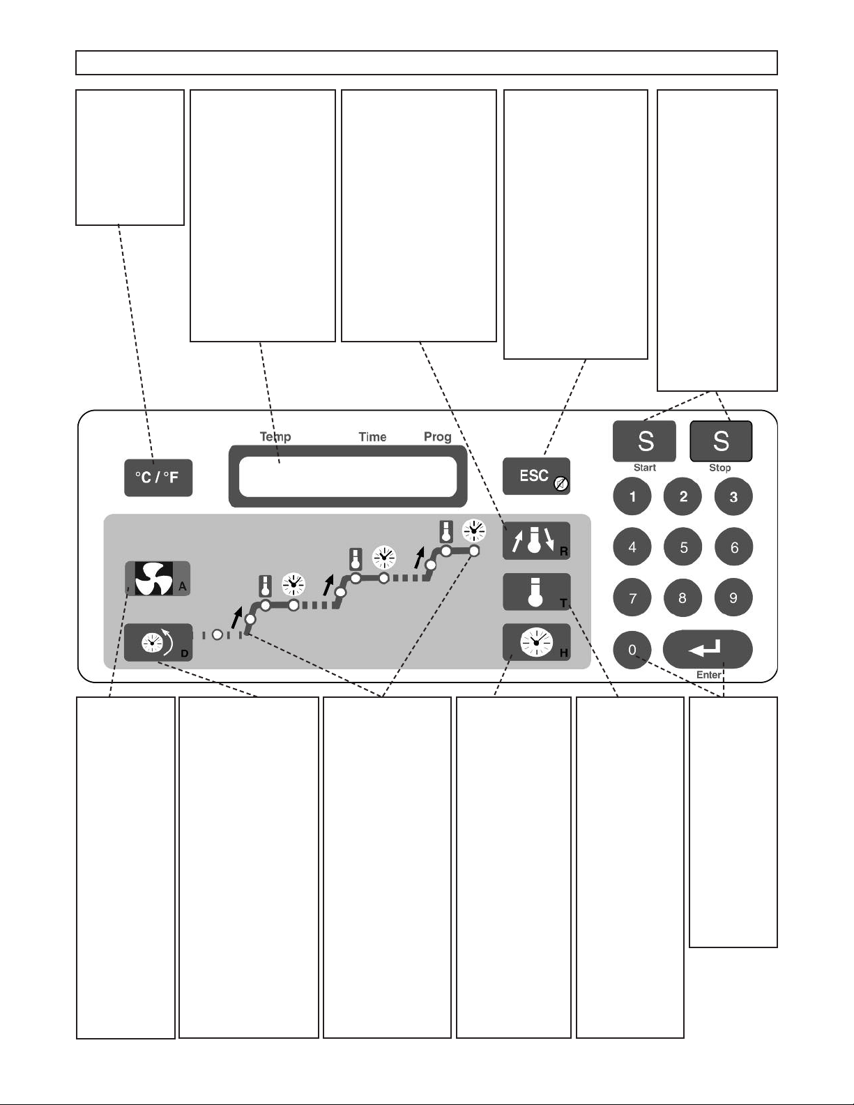
1. Turn on green power switch (right-hand side of control panel)
After a short delay for internal testing, the furnace will display approximate room temperature, program time
(hours:minutes), and program number. All red EDs are off. (If any of the EDs are on, the furnace was already running
a program when it was last turned off.)
2. Select or change the program to the desired number by pressing the digit key (1-9) for the desired program followed by
the ENTER key. The display will be updated to show the new program number and its approximate run time.
3. Pressing the green Start key will start this program. The red EDs will come on and the time will start to count
down. The green power switch will light when the door is closed. The EDs will be turned off as each segment of each
stage of the program is completed.
• During program operation, the total program cycle time is counting down as indicated by the flashing colon in
the time.
• If a program is started when the muffle is already heated, the furnace will heat or cool at the first ramp rate to
the first temperature from the current muffle temperature. It will not cool to room temperature before starting.
• The program will end by maintaining the last muffle temperature, displaying “Hold”, beeping every 3 seconds
and flashing the last Temp ED. See information on End Of Program options (point 1) in the “Setup &
Maintenance” section if other operations are preferred.
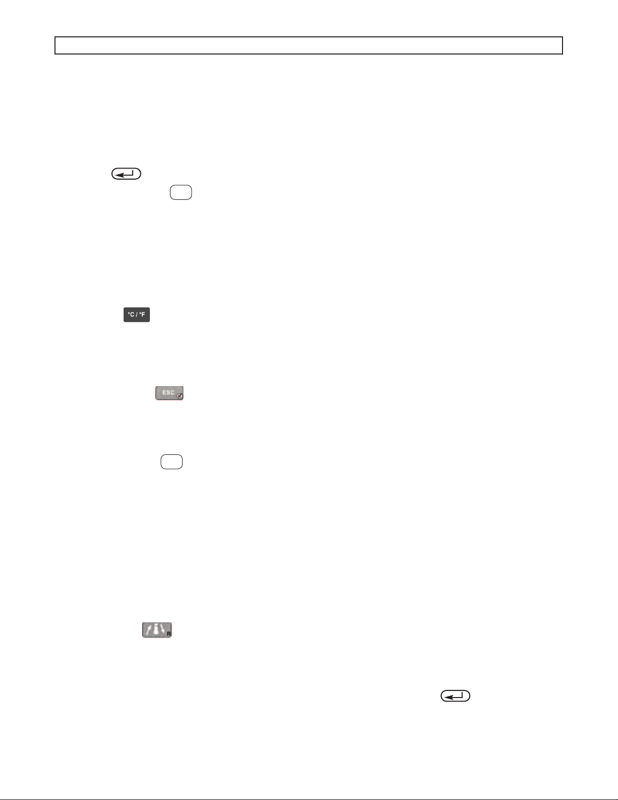
4. Pressing the key will change the temperature display from °C to °F and back. This key is not active during
parameter programming.
5. A short power outage during the operation of a program will not terminate or abort the program unless the muffle
temperature drops more than 32°C (58°F). If the power outage occurs when the muffle temperature is close to, or at
room temperature (e.g. during Delay Start operation) the furnace will continue the program when power is restored
regardless of the temperature drop or the amount of time that has expired.
6. Pressing the Escape key cancels beeping at the end of a program. It also will return the furnace to a display of
the current conditions during programming operations.
7. Opening the door during a cycle interrupts power to the heating elements.
STOPPING A PROGRAM:
1. Pressing the red Stop key will stop the program that is currently running. The red EDs will go out and the
display will show the current program number, approximate cycle time, and the current muffle temperature.
PROGRAMMING:
The furnace increases productivity and reliability for the operator because cycles or programs can be preprogrammed and
operated automatically. Once programmed, the parameters are retained in memory even with the loss of power.
Parameters are not retained in memory if entered during the operation of a program.
Each program is made up of 3 stages which require 3 parameters each. The parameters are grouped into ramp rates (R1,
R2, R3), temperatures (T1, T2, T3), and dwell or hold times (H1, H2, H3). The 1,2,3 indicates the stage number or
sequence. The temperatures can be programmed in either °C or °F; the ramp rates in °C per minute or °F per minute; and
the hold times in hours and minutes (hh:mm).
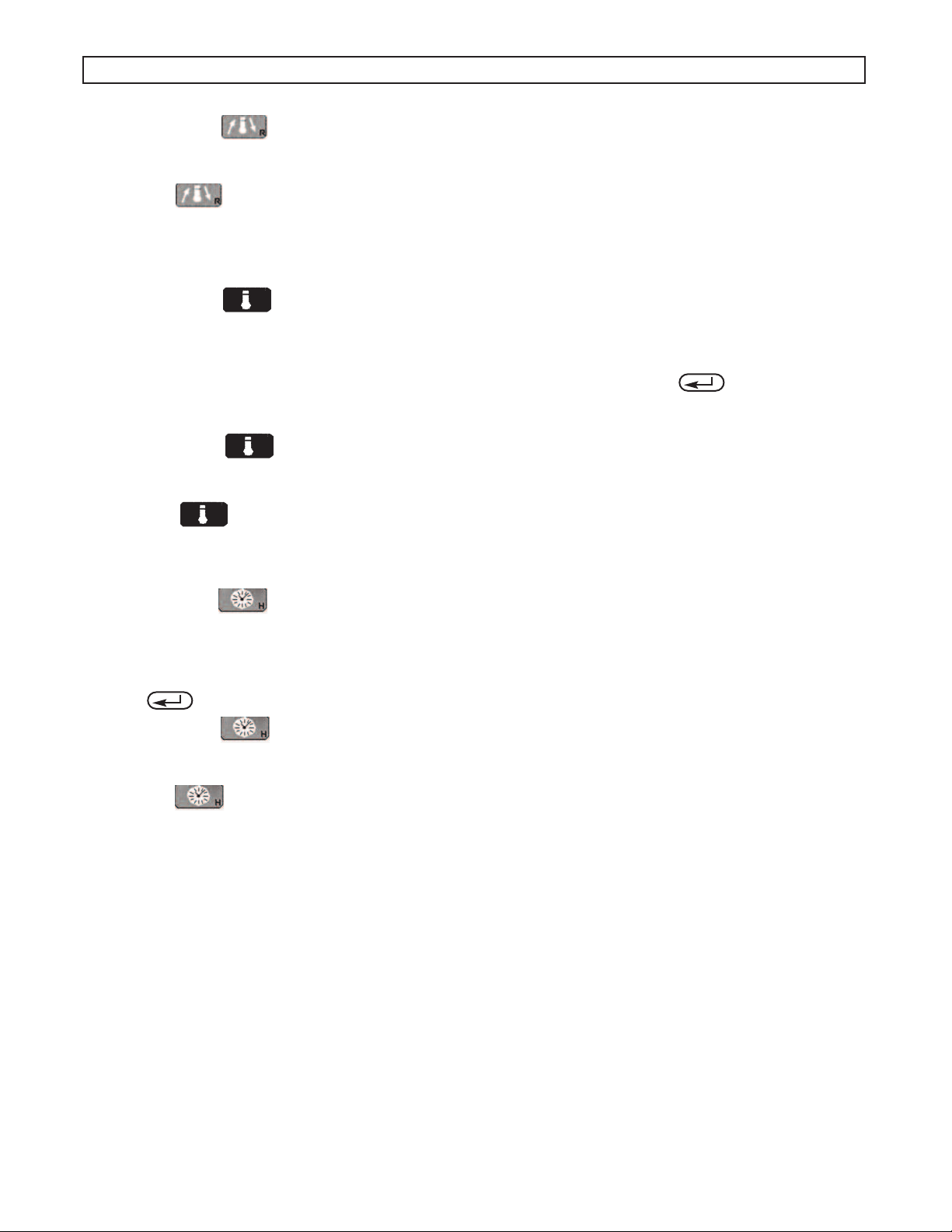
RAMP RATES (R) (0 - 40°C/minute)
1. Pressing the Rate key makes the display show the current value of the R1 parameter followed by 3 blanks for a
new value.
• For example: R1 8.0°C/M ->_ _ _
• The corresponding ED will also light to indicate the selected stage and parameter.
2. Use the digit keys (0,1,2,...,9) to enter the desired parameter value followed by the ENTER key. The new
parameter is now stored in memory.
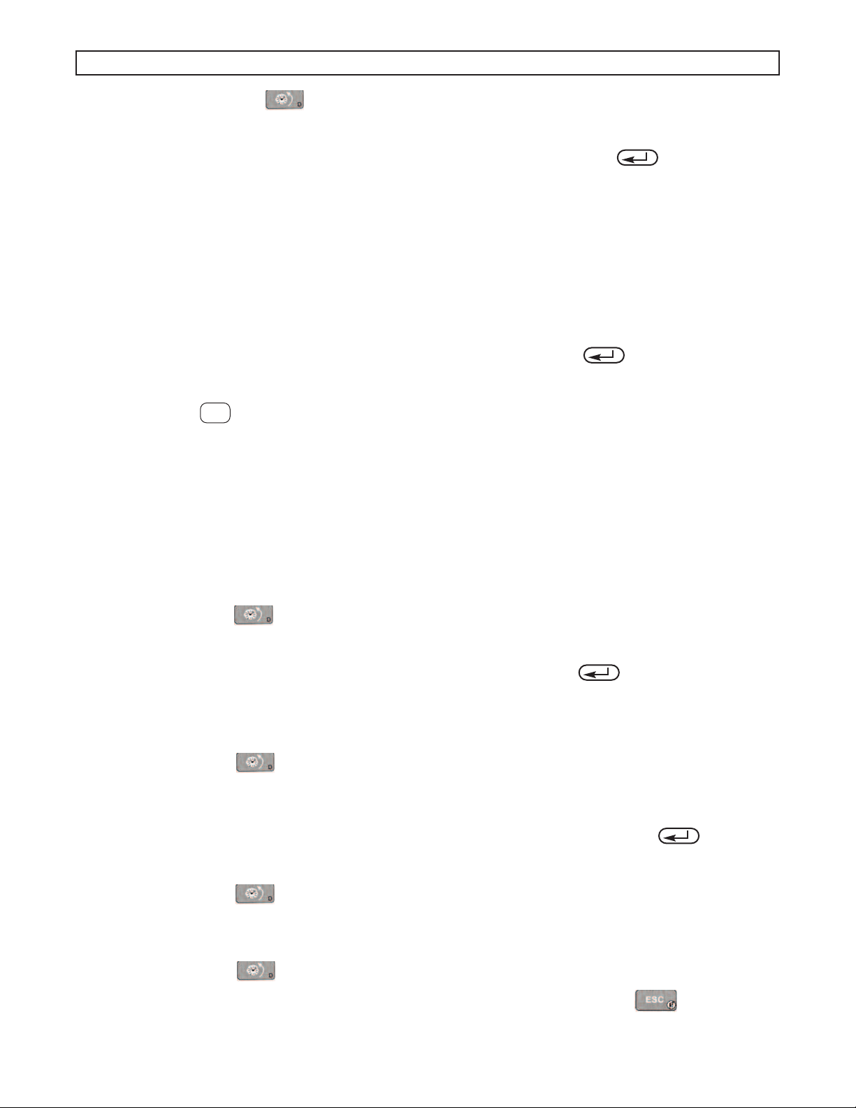
• If a value is entered that is out of the acceptable range, the furnace will beep and display the acceptable range.
• Programming a Rate to 0 will cause the furnace to terminate the remainder of the program stages. For example, if R2
is set equal to 0 then at the end of the first hold time (H1) the furnace will go to the end of the program, making the
S
S
7

program single stage.
3. Pressing the Rate key additional times will display and give access to the Rate parameters for the other two
stages. The 4th time the key is pressed the display circulates back to the beginning and the R1 parameter will be
displayed again.
• The Rate key operates the same if pressed during the operation of a program with the following exception.
The new Rate entered is used only for that one program or cycle and not stored in memory.
• Negative ramp rates are also possible if slower than natural cooling.
TEMPERATURES (T) (50 - 1100°C or Tmax)
1. Pressing the Temp key makes the display show the current value of the T1 parameter followed by 4 blanks for a
new value.
• For example: T1 160°C ->_ _ _ _
• The corresponding ED will also light to indicate the selected stage and parameter.
2. Use the digit keys (0,1,2,...,9) to enter the desired parameter value followed by the ENTER key. The new
parameter is now stored in memory.
• If a value is entered that is out of the acceptable range the furnace will beep and display the acceptable range.
3. Pressing the Temp key additional times will display and give access to the Temp parameters for the other two
stages. The 4th time the key is pressed the display circulates back to the beginning and the T1 parameter will be
displayed again.
• The Temp key operates the same if pressed during the operation of a program with the following exception.
Any new parameter entered is used only for that one program or cycle and not stored in memory.
HO D TIMES (H) (0 - 99:59 hh:mm)
1. Pressing the Hold key makes the display show the current value of the H1 parameter followed by 4 blanks for a
new value.
• For example: H1 1:00H ->_ _ : _ _ (1 hours and 00 minutes)
• The corresponding ED will also light to indicate the selected stage and parameter.
2. Use the digit keys (0,1,2,...,9) to enter the desired parameter value up to 99 minutes and 59 seconds followed by the
ENTER key. The new parameter is now stored in memory.
3. Pressing the Hold key additional times will display and give access to the Hold parameters for the other two
stages. The 4th time the key is pressed the display circulates back to the beginning and the H1 parameter will be
displayed again.
• The Hold key operates the same if pressed during the operation of a program with the following exception.
Any new parameter entered is used only for that one program or cycle and not stored in memory.
AIR EXCHANGE OPERATION
1. The air exchange operation is accomplished by using the venturi principle to draw air out of the muffle and into an
exhaust air flow. The hot muffle air does not pass through the fan. Make up air for the muffle is introduced behind the
muffle heating plates. This indirect air path causes the make up air to preheat before it reaches the muffle cavity to
assure temperature uniformity.
2. The air exchange fan produces about 20CFM of flow when operated at full speed. The vent hood or system being used
for the furnace should have sufficient capacity to accommodate this airflow.
3. The air exchange operation may be controlled for 10 different settings, ranging from 0 to 9 (off to full on). The
maximum setting of 9 on the control performs approximate 5 air exchanges per minute. The curves shown on page 13
show approximate air changes vs. fan setting.
Example: Stage 1 of program 5 can be programmed to a fan setting of 9 while stage 2 of program 5 can be programmed to
a fan setting of 3 and stage 3 of program 5 to a fan setting of 0 (off).
4. The air control settings are retained in memory for each program even when the power is removed.
5. The air control settings are programmed into memory the same way as other parameters. Change to the program
OPERATING INSTRUCTIONS (CONTINUED):
8

number of interest, press the key: once for stage 1, twice for stage 2 and three times for stage 3. The display
shows the current fan level and a new level may be programmed.
A fan speed setting is changed and stored by pressing a digit key (0-9) followed by the ENTER key. A fan setting
change made while a program is operating (running) is only used during that cycle and is not saved in permanent
memory.
The higher the air control setting the slower the furnace will heat. High air control settings with low line voltages may
prevent the furnace from reaching the maximum temperature.
PROGRAM 0
Program 0 is a single temperature hold program. The furnace will heat to this temperature and maintain it as long as
power is applied.
1. Press the 0 key. The display shows the current programmed temperature and the 0 program number.
2. For example: T0 100°C -> _ _ _ _
3. Use the digit keys (0,1,2,...9) to enter the desired temperature followed by the ENTER key. The new parameter
is now stored in memory after 3 seconds. The display shows: 100°C ***** 0 where 100 is the current muffle
temperature, 0 the program number, and ***** indicates that the program is not started.
4. Pressing the Start key will cause the furnace to heat at full power to the programmed temperature. The display
will show “xxxx°C *Hold* 0” “xxxx” is the current muffle temperature, the word “Hold” illustrates single stage and 0
for the program number. The T1 ED will also be on.
SPECIA FEATURES
DE AY START (D)
The Delay Start functions as a timer that automatically starts a program so that it is completed at a selected time up to 7
days later. The delay is programmed in terms of the number of delay days and the desired completion time. The furnace
uses a clock to keep track of time when the furnace power switch is on. If a power outage should occur during a “Delay
Start”, the completion time will be delayed by the length of time the power was off.
Programming The Delay Start:
1. Pressing the Delay Start key makes the display show the current value of the time of day and beep.
• For example: Now = 7:30 -> _ _:_ _
• The corresponding ED will also light to indicate the Delay Start is selected.
2. Use the digit keys (0,1,2,...,9) to enter the current time of day followed by the ENTER key. The new parameter is
now stored in memory. The time of day must be entered in as a 24 hour clock (11:34PM is 23:34), (8:10AM is 08:10).
• Programming the current clock time “Now = 7:30 -> _ _:_ _” is only displayed and requested if there has been a power
outage since the last time the Delay Start was operated Turning the power switch off stops the internal delay start
timer.
3. Pressing the Delay Start key again makes the display show the current value of the Delay D parameter in days.
• For example: Day: 1 [1,2,...,7]
• The corresponding ED will also light to indicate the Delay Start is selected.
4. Use the digit keys (0,1,2,...,7) to enter the desired number of days of delay followed by the ENTER key. The
new parameter is now stored in memory.
• If a value is entered that is greater than 7, then the furnace will display and use 7.
5. Pressing the Delay Start key again displays the program completion time. The furnace will calculate the
approximate time that the program needs to start so that it is completed by the programmed time.
• For example: End = 8:00 -> _ _ :_ _
• The computer uses a 24 hour clock. For example if 14:30 is programmed, the completion time is 2:30 PM.
6. Pressing the Delay Start key again will show the actual time (Now).
• Pressing the key additional times will cycle through the other parameters. Press the Escape key to stop the
function.
S
OPERATING INSTRUCTIONS (CONTINUED):
9

INKING PROGRAMS
Programs can automatically run in sequence by using the inking feature. With this method, a 6 stage (12 segment)
program can be run automatically. Additional programs can also be linked as each program is completed.
Running inked Programs:
1. Press the green Start key with the first program to be run. The furnace will start operation.
2. Use the digit keys (1,2,...,9) to enter the next program number to be run followed by the ENTER key. The furnace
will now run the first program followed automatically by the second. The program cycle time on the display will be the
combination of the two programs. The display will alternately show the first program and then the second program
number will be displayed for a shorter time.
POWER DOOR (3-550PD only)
The remote activation switch is used to operate the power door. Activating the switch once, will cause the door to open or
close. Activating the switch while the door is moving will cause the door to stop. Once stopped, activating the switch
again will cause it to reverse directions.
The furnace will also automatically close the door after a programmed amount of time during a firing cycle. This feature is
disabled at the factory and needs to be activated to operate. See Setup, page 11 for instructions.
S
OPERATING INSTRUCTIONS (CONTINUED):
10

Temp Time Prog
Temp Time Prog
Temp Time Prog
Temp Time Prog
Temp Time Prog
Temp Time Prog
Temp Time Prog
Temp Time Prog
Temp Time Prog
Temp Time Prog
EXAMPLE 1:
It is 10:00 am and I want the burn out to be completed at 4
PM today using program 1.
Set the program you want to run.
Press “1” then “ENTER”
The display will show Prog 1
Set the current time of day (24 hour format).
Press “DELAY”- enter time “10:00”-Press “ENTER”
# The display will show this:
Set the Day you want it to start.
Press “DELAY”-Press “0”-Press “ENTER”
# The display will show this:
Set the finish time (24 hour format).
Press “DELAY”-Press “1600”-Press “ENTER”
# The display will show this:
Set to the “DE AY” mode.
Press “DELAY”-Press “START”
The Display will show this: **
EXAMPLE 2:
It is 3:00 PM and I want the burn out to be completed
tomorrow at 8:00 AM using program 2.
Set the program you want to run.
Press “2” then “ENTER”
The display will show Prog 2
Set the current time of day (24 hour format).
Press “DELAY”- enter time “1500”-Press “ENTER”
# The display will show this:
Set the Day you want it to start.
Press “DELAY”-Press “1”-Press “ENTER”
# The display will show this:
Set the finish time (24 hour format).
Press “DELAY”-Press “0800”-Press “ENTER”
# The display will show this:
Set to the “DE AY” mode.
Press “DELAY”-Press “START”
The Display will show this: **
23˚C 1:01H 2
Now =15:00g15:00
Day: 1 (1,2..7)
End = 8:00g8:00
*Delay Start*2
DELAY SET-UP AND RUNNING A DELAY START PROGRAM PROCEDURE:
26˚C 0:17H 1
Now =10:00g10:00
Day: 0 (1,2..7)
End = 16:00g16:00
*Delay Start*1
11

Temp Time Prog
Temp Time Prog
Temp Time Prog
Temp Time Prog
Temp Time Prog
EXAMPLE 3:
It is 10:00 PM on Friday and I want the burn out to be
completed Monday at 7:30 AM using program 3.
Set the program you want to run.
Press “3” then “ENTER”
The display will show Prog
Set the current time of day (24 hour format).
Press “DELAY”- enter time “2200”-Press “ENTER”
# The display will show this:
Set the Day you want it to start.
Press “DELAY”-Press “3”-Press “ENTER”
# The display will show this:
Set the finish time (24 hour format).
Press “DELAY”-Press “0730”-Press “ENTER”
# The display will show this:
Set to the “DE AY” mode.
Press “DELAY”-Press “START”
The Display will show this: **
NOTE: THINGS TO REMEMBER
Day 0 = today
Day 1= tomorrow
If you operate a night shift
12 midnight = 24:00 hours and 1am = 01:00
End Time means the approximate time the process will be
finished.
# You may need to press the “Delay” several times to make
sure the display shows the proper mode of operation
NOW, END or DAY.
** If you are trying to program and end time sooner than
the amount of time it takes the furnace to complete all
stages of the process your furnace will start as soon as
you press START.
DELAY SET-UP AND RUNNING A DELAY START PROGRAM PROCEDURE (CONTD):
23˚C 4:16H 3
Now = 22:00g22:00
Day: 3 (1,2..7)
End = 7:30g7:30
*Delay Start*3
12

PARAMETER
• Temperature Range: 50°C (122°F) - 1100°C (2012°F) / 1° Resolution
• Hold Time Range: 0:00 - 99:59 (hours:minutes) / 1 Min Resolution
• Ramp Rate Range: 0 - 40.0°C/minute (72°F) / 0.1°C Resolution
• Temperature Accuracy: ± 5°C (± 9°F) at steady state
• Muffle Temperature Uniformity: ± 8°C (± 15°F) at steady state
ELECTRICAL
3-130 3-550 3-550PD 3-550A 3-1750 3-1750 3-1750A
(EURO)
Voltage Range: 100-120 ---- ---- ---- ---- ---- ----
@ 50/60Hz ---- 120 120 ---- ---- ---- ----
---- ---- 230 230 230 230 230
200-240 200-240 ---- ---- ---- 200-250 ----
Steady State
Current: Amps @
100V ---- 14.7 14.7 ---- ---- ---- ----
120V 12.0 16.0 16.0 ---- ---- ---- ----
230V ---- ---- ---- 9.6 19.0
240V 4.4 10.0 10.0 ---- 20.0 19.0 ----
Max Power Watts: 1440 (120V) 1470 (100V) 1470(100V) 2204 4800 4370 4370
1060 (240V) 1920 (120V) 1920 (120V)
2400 (240V) 2400 (240V)
Watts to Maintain 525 1050 1050 1050 2200 2200 2200
1000°C (1832°F)
(Air Exchange
setting @ 0)
EN IRONMENTAL
• Ambient Operating Temperature: 5 - 40°C (41-104°F)
• Relative Humidity: Maximum 80%, non-condensing
SPECIFICATIONS:
13

OUTLINE DRAWINGS MM(IN)
MECHANICA
Exterior Dimensions:
MODE ABCD
130 510mm (20.0”) 350mm (13.8”) 290mm (11.5”) 330mm (13.0”)
550 635mm (25.0”) 410mm (16.0”) 400mm (15.8”) 430mm (17.0”)
3-550A 635mm (25.0”) 430mm (17.0”)* 400mm (15.8”) 489mm (19.3”)*
3-550PD 635mm (25.0”) 430mm (17.0”)* 400mm (15.8”) 489mm (19.3”)*
1750 815mm (32.0”) 545mm (21.5”) 610mm (24.0”) 535mm (21.0”)
3-1750A 815mm (32.0”) 541mm (21.3”) 610mm (24.0”) 584mm (23.0”)*
* Dimension includes exhaust tube
Internal Muffle Dimensions:
MODE EFG
130 120mm (4.6”) 140mm (5.7”) 130mm (5.2”)
550 180mm (7.0”) 230mm (9.0”) 230mm (9.0”)
3-550A 180mm (7.0”) 230mm (9.0”)* 230mm (9.0”)
3-550PD 180mm (7.0”) 230mm (9.0”)* 230mm (9.0”)
1750 250mm (10.0”) 360mm (14.0”) 320mm (12.5”)
3-1750A 250mm (10.0”) 360mm (14.0”) 320mm (12.5”)
Model Furnace Weight: Shipping Weight:
130 11 kg (25 lbs.) 16 kg (35 lbs.)
550 20 kg (45 lbs.) 27 kg (60 lbs.)
3-550A 23 kg (51 lbs.) 28 kg (62 lbs.)
3-550PD 23 kg (51 lbs.) 28 kg (62 lbs.)
1750 45 kg (100 lbs.) 61 kg (135 lbs.)
3-1750A 55 kg (120 lbs.) 67 kg (148 lbs.)
A
B
DC
G
E
F
14

SETUP:
The Vulcan furnace goes through a self test that lasts for 4 to 6 seconds each time that power is applied. After the test,
the display will show the word “SETUP?” for approximately 5 seconds. In the Setup mode, several different options are
available for the user to select.
The first is the END OF PROGRAM operation which allows the user to select how the furnace should operate at the end of
the program. The second is the TMAX parameter which limits the maximum temperature that can be programmed into the
furnace. The last is TEMPERATURE ADJUSTMENT/CA IBRATION which allows the user to alter the furnace temperature
calibration.
1. Turn on power to the furnace. Pressing the ENTER key when the word “Setup?” is being displayed will start the
Setup mode first with the End of Program options.
• The current END OF PROGRAM option is now displayed as “Hold = 1 (2),(3)”. The (1) option is the factory default. It
will cause the furnace to maintain or hold the last programmed temperature, display “Hold” and beep every 3
seconds until the red Stop key is pressed. Pressing the Escape key will stop the beeping but not the
program.
• The (2) option will cause the furnace to maintain or hold the last programmed temperature, and display “Hold” but
without beeping until the red Stop key is pressed.
• The (3) option will cause the furnace to turn off and cool to room temperature at the end of the program and display
“End”. The Stop key does not have to be pressed.
• Use the digit keys (1,2,3) to change the END OF PROGRAM option.
2. Pressing the ENTER key when the desired End Of Program is selected will store it in memory and then advance
to TMAX which is the next option. The TMAX value limits the maximum temperatures that the furnace can be
programmed to or fire to. The factory setting for TMAX is 1100°C. Use the digit keys (0,1,2,...,9) to enter the desired
TMAX value followed by the ENTER key. The new Maximum Temperature is now stored in memory and the next
option is displayed.
3. 3-550PD only) The automatic closing portion of the Power Door feature is shipped from the factory in the disabled
condition of 0 (Door 0sec-->). A delay time before closing of 1 to 99 seconds can be entered to activate the auto
closing. The automatic closing is only active during firing cycles.
4. The final option is the temperature adjustment/calibration which is displayed as “Tcal 1000°C->_ _:_ _”. The factory
setting for Tcal is 1000°C. Use the digit keys (0,1,2,...,9) to enter the desired Tcal value followed by the ENTER
key. The new Temperature Calibration is now stored in memory. Entering a 1000 will return the furnace to the factory
calibration. See the next section on Temperature Adjustment/Calibration for specifics on how to determine the
adjustment number.
TEMPERATURE ADJUSTMENT/CALIBRATION:
Every VU CAN furnace is calibrated in the factory at 1000°C. Under normal use the furnace should not require calibration.
The electronics used in the VU CAN furnaces are very stable and will have minimal drifts over the life of the furnace.
Thermocouple replacement could be a potential requirement for calibration if high accuracy is required.
This calibration can be altered by entering a new Tcal value in the Setup mode listed previously. The Tcal value has a
range of 900 to 1100°C.
For example: A program is operating at a stable temperature and a separate thermocouple is inserted in the furnace and a
digital thermometer measures the muffle temperature. The display shows 875°C which is the programmed temperature
but the digital thermometer reads 868°C. A new calibration value could be calculated by dividing the display temperature
by the actual temperature (digital thermometer) and then multiplying by the current Tcal value (factory default is 1000°C).
In this case the result is 1008 (875/868 = 1.008; 1.008 * 1000 = 1008). 1008 is entered in as the Tcal value. With this
method the furnace calibration can be done at the normal operation temperature.
Second example: Programmed temperature is 1050°C and the digital thermometer reads 1065°C. The old Tcal value is
985°C.
(1050/1065 = 0.986 then 0.986 * 985 = 971) 971 should be entered as the new Tcal value.
CLEANING:
• Vacuum dust and dirt from the furnace rather than attempting to blow the dust off. This will minimize the amount of air
born particles.
• Use a soft damp cloth to clean the control panel. Avoid excess water or solution when cleaning the furnace. These
solutions can attack the panel or electronics and cause the furnace to malfunction.
S
S
SETUP & MAINTENANCE:
15

ERROR CODES:
Err codes can be cleared from the display by turning the front panel power switch off and then on again.
Code Description Possible Cause
Err 1 Over Temperature Temp > 1120°C, shorted thermocouple, shorted triac, shorted optotriac, wiring
connections, computer PCB
Err 2 Open Thermocouple (TC) Open TC tip, connection to TC, TC to PCB connection, computer PCB
Err 3 Temp > Tmax Muffle temperature has exceeded the programmed limit temperature TMAX
(see SETUP)
Err 7 Brown-out ow line voltage < 90VAC (<190VAC for 200-240V), wall socket shared with
other loads, furnace connected with extension cord
Err 8 EEPROM error Parameter program memory error; computer PCB
Err 19 ine frequency No line frequency detected, computer PCB
TROUBLESHOOTING THE ULCAN 3-SERIES FURNACE
TROUBLESHOOTING:
PROB EM CHECK IST / CAUSES
Dead, Not Operating - Check power receptacle or outlet for power.
No Power / Display - Check line or power cord connections.
- Turn on green power switch.
- Check fuse (20 amp) and lamp on control PDB.
Not Heating During Program - Is door completely closed? Door switch may be interrupting power.
Operation - Check heating element plates for continuity.
Door Too oose or Tight - The amount of force or drag on the door movement can be changed by adjusting the
hex screws (both sides should be adjusted equally) located on the upper rear corners
of the furnace cabinet. Turning the screw clockwise adds drag and requires more
force.
Heating Too Slow - Rate programmed wrong. 1.5°/minute rather than 15.0°/minute.
- arge loads will slow down response time and increase the time to temperature by 2
to 5 times.
- Muffle near end of life.
Program Turns Off Too Early - Programming a Rate to zero will terminate the remainder of the program.
- End of program option has been changed from 1 or 2 to option 3 which turns off the
furnace at the end of the program [End].
Power Door Does Not Open - A hidden switch to activate the door is located between the °C/°F key and the Delay
(3-550PD only) Start key. Try pressing it to test the operation.
- Check activation switch connections to back of furnace.
- Allow the furnace to cool and test the door by activating the switch and then lifting
up/pushing door on the door in the appropriate direction of travel.
Fan Does Not Operate - Operates only in a start cycle
(Air Exchange Model Only) - Setting of 0 means no fan active
16

ACCESSORIES:
DESCRIPTION PART NUMBER
Tongs; 30cm (12”) Stainless Steel 9390015
Tray- Bottom, Model 130 9353053
Tray- Bottom, Model 550 9353057
Tray- Bottom, Model 1750 9353060
Shelf - free standing, Model 550 9493327
Shelf - Model 1750 9493396
Muffle Hardening Agent 9491006
Temperature Sticks
705 °C (1300 °F) 9199073
815 °C (1500 °F) 9199074
Exhaust port ball plug
Small (130, 550) 9491093A
arge (1750) 9492456
Service Manual, VU CAN 9363049
17
This manual suits for next models
6
Table of contents
Other Vulcan-Hart Furnace manuals
Popular Furnace manuals by other brands

VERDER
VERDER CARBOLITE GERO AAF-BAL 11/17 Installation, operation and maintenance instructions

Bryant
Bryant 367AAN User's information manual

Carrier
Carrier 58MCA series Installation and operating instructions

ICP
ICP N9MP1 Service manual

Goodman
Goodman GMS90453BXA repair parts

Amana
Amana GUIA070A30 Service instructions

Goodman
Goodman GMV95 Series installation instructions

Lennox
Lennox Allied Air L83UF installation instructions

Allied
Allied A80UH2V installation instructions

Johnson Controls
Johnson Controls TPLC060A12MP12C Quick reference guide

Payne
Payne PG8M Installation, Start-Up and Service Instructions

Yukon
Yukon LWO-112 owner's manual